AROUND TOTAL HIP REPLACEMENTS
USING GUIDED BONE REGENERATION
By
REJ-PAUL BHUMBRA
SUBM ITTED FOR TH E DEG REE OF DOCTOR OF PHILO SO PHY IN TH E U NIVERSITY OF LONDON
SEPTEMBER 1998
CENTRE FOR BIOMEDICAL ENGINEERING
U NIVERS ITY COLLEGE LONDON MEDICAL SCHO O L ROYAL NATIONAL ORTHOPAEDIC HOSPITAL T R U S T
All rights reserved
INFORMATION TO ALL USERS
The quality of this reproduction is dependent upon the quality of the copy submitted.
In the unlikely event that the author did not send a complete manuscript and there are missing pages, these will be noted. Also, if material had to be removed,
a note will indicate the deletion.
uest.
ProQuest U642275
Published by ProQuest LLC(2015). Copyright of the Dissertation is held by the Author.
All rights reserved.
Abstract
number
Acknowledgements List of Figures
List of Tables
Chapter One Chapter Two Chapter Three Chapter Four Chapter Five Chapter Six
Appendix I
References
Introduction to Total Hip Arthroplasty And Guided Bone Regeneration Biocompatibility & the In Vitro
Properties of e-PTFE & butyl-cyanoacrylate adhesive
Enhanced Bone Formation and Osseointegration using Guided Bone Regeneration
Tribology & the Need for W ear Testing
The prevention of W ear Debris induced Osteolysis using Guided Bone
Regeneration Discussion
Total Hip Arthroplasty in the Goat. Anaesthetic & Surgical Considerations
‘SEALING TH E BONE-IMPLANT INTERFACE IN TOTAL HIP REPLACEM ENTS USING GUIDED BONE REG EN ER ATIO N ’
The aim of this project was to prevent wear debris from reaching the interface
of the acetabular cup and femoral component by the use of a partially occlusive
e-PTFE membrane. This membrane would initially act as a physical seal, which
would become incorporated by bone and soft tissue, forming a secondary
biological seal. The hypothesis was that these physical and biological seals,
would prevent the debris from accessing the interfacial tissues where they
cause bone loss and implant loosening.
The biocompatibility of the membrane, and the glue used to attach the
membrane was initially assessed by in vitro testing. Osteosarcoma cell
proliferation over e-PTFE used with butyl-cyanoacrylate for 24 hours occurred
at 20% the rate of controls. In a rabbit study, the membrane protected a
femoral defect into which bone would grow more rapidly than an unprotected
site. The second component of the rabbit study demonstrated that e-PTFE
significantly (P<0.02) enhanced the osseo-integration of a trans-femora!
titanium screw. A wear test characterised a surface roughness and morphology
that wore at a known accelerated rate, producing particles of the same number,
size and shape to those seen around human hip replacements after ten years.
An animal model was developed to test the hypothesis. The model would
replicate the mechanisms of loosening where the effects of wear debris could
be studied. Using femoral heads with the appropriate roughness, as
determined by the wear test, a goat model produced the radiological and
histological presentation of loosening as observed in human total hip
replacements. Loosening was assessed by measurement of the radiolucent
line, and attributable to wear debris by histological investigation. The e-PTFE
membrane prevented acetabular implant loosening, to a statistical significance
Dr. Gordon Biunn supervised this project. He has devoted much of his time to the success of the work. I am extremely fortunate to have been his Ph.D. student and I am grateful for the professional and personal contribution he is continuing to make. W .L. Gore and Associates, represented by Andrew Berman and Jansen Emmanuel, have funded the work. They have both been an absolute pleasure to work with.
The research was performed at the Centre for Biomedical Engineering at the Royal National Orthopaedic Hospital in Stanmore. It has been a luxury to work in such an environment. I am indebted all of the members of staff at Biomedical Engineering and Stanmore Implants Worldwide, headed by Professor Peter Walker. They have all, in their own and individual ways, contributed directly to myself and this work. I hope I have and will give some of what I owe, back.
I am grateful to Mr. David Barrett, from Southampton University Hospital, for his demonstration that an orthopaedic surgeon and a scientist can be embodied in one person. Mr. Stephen Cannon and Dr. Neville Robinson have contributed to my understanding of orthopaedic surgery, medicine, and enjoyment of 'work.' They have been quintessential in my appreciation of what we do orthopaedic research for.
Gary Bhumbra has very kindly taken the time to proof-read this thesis.
Conducting Research at the Royal National Orthopaedic Hospital has afforded me the freedom of working with a number of individuals with whom I feel privileged to have come into contact with. I gratefully acknowledge the support of those people and they have my utmost respect.
The irony o f ‘Acknowledgements’ is that they tend to give more o f an
indication of the person writing them, than the people being written
Fig. No.
Caption Page
number
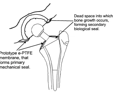
1.1 Schematic for Membrane Placement 16
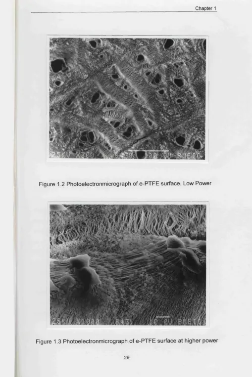
1.2 Photoelectronmicrograph of e-PTFE surface. Low
Power
29
1.3 Photoelectronmicrograph of e-PTFE surface at
higher power
29
1.4 Photoelectronmicrograph of section through e-
PTFE
30
teüM É
2.1 Cell Proliferation in Elutant Dilution 44
2.2 Cell Proliferation over Different Surfaces 45
3.1 Schematic of Bone Defect 51
3.2 Schematic for the use of Guided Bone
Regeneration in the Osseo-mechanical integration
of prostheses
52
3.3 Control operative site 53
3.4 Test operative site covered with e-PTFE square 54
3.5 Woven Bone in Control site after 2 weeks 55
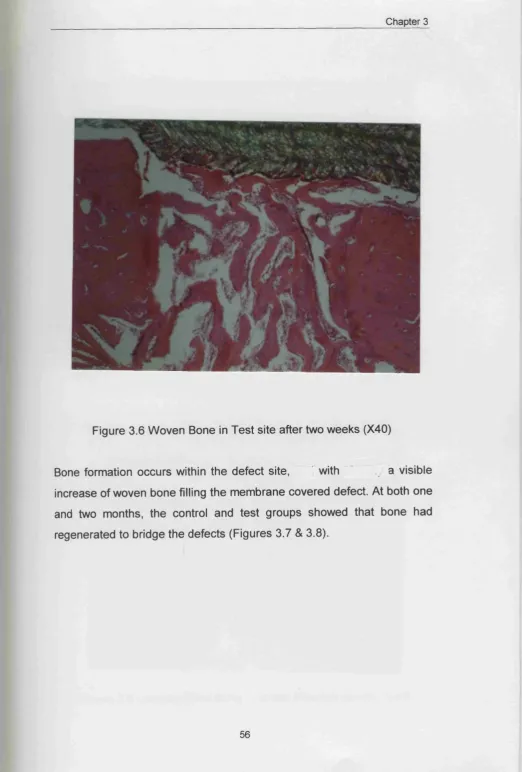
3.6 Woven Bone in Test site after 2 weeks 56
3.7 Lamellar Bone in Control site after 2 months 57
3.8 Lamellar Bone in Test site after 2 months 57
3.9 Osteoblasts in e-PTFE matrix 58
3.10 e-PTFE significantly enhanced Bone Regeneration 59
3.11 e-PTFE significantly enhanced osseointegration 60
3.12 Little bone regeneration into defect and around
implant
3.15 Complete Bone integration of Implant in Test
Group
63
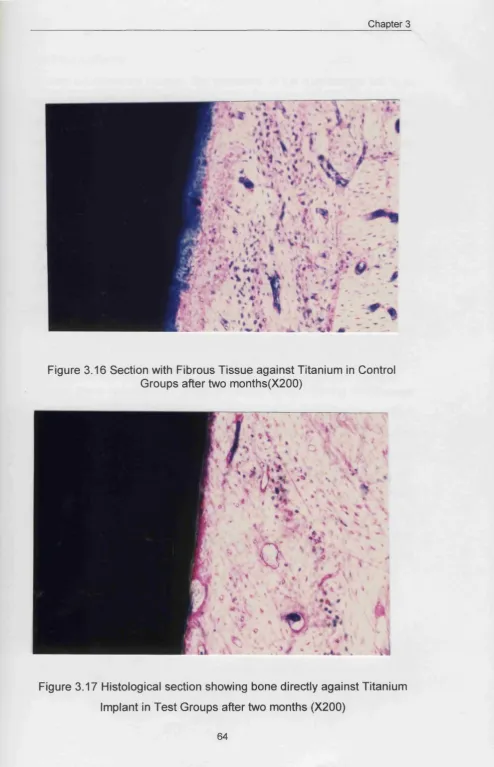
3.16 Fibrous tissue in contact with Titanium in Control
groups
64
3.17 Bone directly against Titanium Implant in Test
Groups
64
4.1 Different Abrasive Wear Mechanisms 69
4.2 Profilometer Schematic 72
4.3 Average Roughness Trace 73
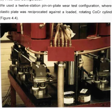
4.4 Test Rig for Abrasive Wear Test 80
4.5 Test Schematic 81
4.6 Rougher Papers Produce a Higher Average
Roughness
84
4.7 Scratched CoCr Surface (X I00) 84
4.8 Scratched CoCr Surface ( X I500) 85
4.9 Shot-Blasted Surface with Entirely Different
Morphology
85
4.10 Rougher surfaces increase the Height of the
Asperities
86
4.11 Adjacent Peaks Further apart in Rough & Polished
surfaces
87
4.12 Volume Loss from Polyethylene Discs(l) 88
4.13 Volume Loss from Polyethylene Discs(2) 89
4.14 Weight Loss from Polyethylene Discs(l) 90
4.15 Weight Loss from Polyethylene Discs(2) 90
4.16 Wear Factor Expressed for Each Grit Paper 91
4.17 SEM Photomicrograph Showing Adherent Poly
Particle
92
4.18 Graph Demonstrating Extent of Polishing of CoCr
pins
92
4.20 Polyethylene Particles from Grit Paper 600 94
4.21 Polyethylene Particles from Grit Paper 1200 94
4.22 Polyethylene Particles at a Larger Mag. from Grit
Paper 600
95
4.23 Polyethylene Particles at a Larger Mag. from Grit
Paper 240
95
4.24 Graph of Polyethylene Particle Distribution 97
5.1 Dimensions of e-PTFE membranes used for
implantation
105
5.2 Intra-Operative View of Control Hip Insertion 107
5.3 Intra-Operative View of Test Hip Insertion 108
5.4 Sectioning Criteria of Goat Hip 114
5.5 Scanned Acetabular section radiograph 117
5.6 Average Roughness of Femoral Heads 122
5.7 Mean-Peak-to-Valley Distances of Femoral Heads 123
5.8 Mean Spacing Between Peaks of Femoral Heads 123
5.9 Wear of Rough heads in e-PTFE and Control
Groups
125
5.10 Wear of Rough and Smooth heads 125
5.11 Polyethylene Particles in Hip Capsule 126
5.12 Numbers of Polyethylene Particles from rough
heads only
127
5.13 Numbers of Polyethylene Particles 128
5.14a
b & c
Control 4, 8 & 12 Month Post-Operative
Radiographs
129-131
5.15a
b & c
5.20 Varying Extents of Loosening in Control and Test Groups
136
5.21 e-PTFE reduced the Extent of Loosening 137 5.22 Similar Extents of Loosening in Control and Test
Groups, except proximo-medially
138
5.23 No Difference between Groups in Distal Femora 141 5.24 Control Cup with Roughened Head 142 5.25 e-PTFE sealed acetabular interface 143 5.26 Cement-Bone Interface at margin for e-PTFE
group ( X I 00)
144
5.27 Fibrous Tissue Interposing the Bone and Cement at the Cup Margin for the Control Groups
145
5.28 Polarised Image of Fibrous Tissue Interposing the Bone and Cement at the Cup Margin for the Control Groups
145
5.29 Osteolytic W edge in control groups (X40) 146 5.30 Osteolytic detail from resorption wedge in control
group (X200)
147
5.31 Macrophage detail from osteolytic wedge in control group (X200)
147
5.32 Macrophage detail showing intracellular birefringence (X200)
148
5.33 SEM micrograph of intimate lamellar bone-e-PTFE contact
149
5.34 e-PTFE bone interface, with osteoblastic penetration
150
5.35 Two cell populations growing either side of the e-PTFE membrane
144
5.36 Soft-tissue integrating e-PTFE interface ( X I 00) 152
5.37 Resorption wedge of femoral component in control groups (X40)
5.38 Resorption wedge of femoral component in control groups (Polarised) (X40)
153
5.39 Swollen Macrophages at the Proximal End of the Medial Femoral Component in the Control Group (X200)
154
5.40 Macrophages containing Biréfringent Material at the Proximal End of the Femoral Component in the Control Group (Polarised) (X200)
154
5.41 Fibrous tissue between the cement and bone in the Proximal Femur as noted in both test and control groups (X200)
155
5.42 e-PTFE and titanium in close approximation on the proximal femoral component, at the shoulder
156
5.43 Well-bonded cement mantle in control group 157 5.44 Collagen Layer in between Cement and Bone in
Transverse Femur
158
5.45 Schematic of Intra-capsular structures 159 5.46 Swollen Macrophages and collagen ( X I 00) 160 5.47 Intracellular Birefringence with collagen
birefringence ( X I 00)
160
5.48 Macrophages in hip capsule tissue (X400) 161 5.49 Birefringence within Macrophages (X400) 161 5.50 Scanning Electron Micrograph of a Plasma etched
Resin section
162
5.51 Macrophages containing Biréfringent material, surrounded by lymphocytes
Table No.
Caption Page
Number
1.1 Possible Complications Following THA 6 1.2 Cellular Distribution of Particulate Debris 13 1.3 Options for Replacement of Bone Defects 22 4.1 Average Roughness Values for Pins in First Test 86 4.2 Average Roughness Values for Pins in Second
Test
88
5.1 Surgical summary of Goat Operative Procedures 110
5.2 Post-Operative Exercise Regime 110
5.3 Processing of en bloc Goat Sections 113
5.4 Results Format 121
C hapter 1 Introduction to Total Hip Arthroplasty
and Guided Tissue Regeneration
1 The Problem
2 The Evolution of Total Hip Arthroplasty
3 Total Hip Arthroplasty. Current Practices
4 Indications and Contraindications for Total Hip Arthroplasty
5 Complications following Total Hip Arthroplasty
6 Aseptic Loosening and Particulate Debris
7 Femoral Implant Failure Mechanisms
8 Acetabular Implant Failure Mechanisms
9 The Cellular Responses to Particulate Debris
10 The Role o f Micromotion
11 The Hypotheses
12 The Concept of Guided Tissue Regeneration
13 Guided Bone Regeneration. A Historical Perspective
14 The Biological Basis for Guided Bone Regeneration
15 Expanded Polytetrafluoroethylene (e-PTFE)
16 Practical Aspects of Guided Bone Regeneration
.17 The Use of Butyl-cyanoacrylate Adhesive
1.1 THE PROBLEM
Osteoarthritis (OA) is a degenerative disorder of articular cartilage. W hen conservative treatment regimes have failed the damaged cartilage can be replaced by metallic and polymeric components, used for total hip arthroplasty (THA).
Although this is a very successful treatment, the problem is that these components do not remain attached to the bone in the long term, due to bone loss around the components.
1.2 TH E EVOLUTION OF TOTAL HIP ARTHROPLASTY
McKee and Charnley independently introduced the modern form of THA, although it was Charnley’s “low friction” metal on polyethylene combination that proved more popular. This procedure is one of the landmark surgical successes of this century and since 1961 has remained the gold standard by which other types of implants are judged. Over the past forty years, no major improvement in the longevity of primary hip replacement has been made.
The problem of the hip osteoarthritis is not new in the bipedal human. Half a million years ago, the ‘Java’ man was afflicted, as well as the Ancient Egyptians and Romans (Jayson 1971). W hite performed an excision arthroplasty' in 1822 at the Westminster Hospital of London, on a nine-year old boy with a septic and deformed hip. A deformed and ankylosed hip was treated in 1826, using an intertrochanteric osteotomy (Barton 1827). These techniques did not allow mobility in the long term. In order to maintain the range of motion obtained intraoperatively, inter-positional arthroplasty was attempted, using muscles (Oilier 1885), gold foil (Jones 1921), and wooden blocks (Carnochan 1860). These did not last, since the materials wore off the bone surfaces.
W iles (1958), McKee (1951), Moore (1952), and Thompson (1952) introduced the metallic generation of prostheses. In 1960, Charnley introduced the concept of low-friction arthroplasty of the hip. This consisted of a stainless steel femoral head, and a polytetrafluoroethylene (PTFE) cup. The PTFE wore unacceptably, producing particulate PTFE debris that caused bone osteolysis. The PTFE was replaced by High Density Polyethylene. W ear of the acetabular component is now the longer term problem facing the survivorship of the components used in total hip arthroplasty.
1.3 TOTAL HIP ARTHOPLASTY. CURRENT PRACTICE
The current procedure involves removal of the femoral head and most of the neck, as well as enlargement of the acetabulum, without removal of the trochanter. The acetabulum is lined with a hemispherical UHM W PE (Ultra-High Molecular Weight Polyethylene) component.
The UHM W PE cup can be cemented directly into the acetabulum. Alternatively the component is metal-backed and locked into the acetabulum, with or without screws or cement. There are various types of finishes used on the metallic surface, including porous beads, wire mesh, or hydroxyapatite. Bipolar prostheses with the head captive within a metal “cup” allow free movement of the metal-backed cup over the acetabular surface.
The femoral stem is inserted with or without cement depending on the design. Cemented stems can be produced with a layer of polymethylmethacrylate over the stem to aid cement attachment just after insertion. Uncemented stems are pre-coated with hydroxyapatite to promote early mechanical osseointegration. There are also custom designs that fit the medulla of the individual femur of each patient, produced by Computer Aided Design-Computer Aided Manufacture (CAD-CAM) methods.
1.4 INDICATIONS AND CONTRAINDICATIO NS FOR TOTAL HIP ARTHROPLASTY
The introduction of THA was thought to be an alternative to procedures such as arthrodesis or excision arthroplasty. Patient selection is a major determinant for a successful outcome from THA. THA is indicated in many patients with arthritic diseases in which conservative medical management has failed.
Osteoarthritis is the most common indication for THA (Charnley and Cupic 1973, Harris and Sledge 1990). Other indications include rheumatoid or juvenile chronic arthritis, osteoarthritis secondary to, osteonecrosis, trauma, haemophilia or Gaucher s disease.
Younger and middle-aged patients should be evaluated very carefully before an operation is considered. Successful THA remains largely an operation for the elderly, and until new technologies produce results to significantly prolong the life of Total Joint Prostheses, the responsible surgeon must bear this in mind.
1.5 COM PLICATIONS FOLLOW ING TOTAL HIP ARTHROPLASTY. A number of complications can occur post-operatively, and are divided into local and systemic, as well as immediate, early and late.
Immediate Early Late
Local Neurovascular injuries
Leg length discrepancy
Acute infection
Dislocation
Delayed infection
Aseptic loosening Heterotopic ossification Femoral fractures Late haematogenous Infections
Systemic Hypotension from
methyl-methacrylate monomer. Deep-vein Thrombosis Fat Emboli ? Sensitivity? ? Malignancy?
able 1.1. Possible Complications Following THA
Revision surgery is associated with more adverse complications than primary cases. Revision operations present with significant bone loss, requiring specialised prostheses and/or bone grafting.
There is no doubt that THA is a successful operation, making it very popular among both orthopaedic and general surgeons. The longevity of cemented hips in patients of 60 years and older is 90%, surviving at least ten years after surgery (Charnley and Cupic 1973). However, the upper limit to the working life of most prostheses is 15 years. The more the operation is performed, the more significant the failure rate becomes therefore increasing the need for a successful primary operation.
1.6 ASEPTIC LOOSENING AND PARTICULATE DEBRIS
Charnley’s use of polytetrafluoroethylene cups produced a failure rate of over 95% (Charnley 1963). Having changed to UHM W PE, the next main problem was deep sepsis. Once the incidence of infection was reduced, endosteal lysis appeared and joints continued to loosen. McKee also noticed endosteal erosion, but considered the process to be mechanical in origin (McKee and W atson-Farrar 1966).
Willert and Puls (1972) originally proposed that wear debris, generated at the articulating surfaces, during the clinical life of a joint replacement, may cause osteolysis and subsequent loosening. Debris is also produced by abrasions of the stem/cement/bone interfaces in the medullary canal, as well as by fretting at the spigot-head junction in modular components.
The debris is ‘processed’ by the immunological mediators of the host. Proportions of these particles are transported via the lymphatics to lymph nodes (Langkamer et al. 1992, Case at al. 1994, Shea at al.
1996). Other particles remain within the joint space causing third body wear, or reside in the synovium potentiating synovitis. The remaining particulate debris migrates to the prosthetic interfaces.
Several authors have assessed the quality of TH R in which pain and functional ability were emphasised (Charnley 1979, Hierton at al. 1983, McCoy atal. 1988). Younger patients benefited from less pain with more mobility but lost more bone; less bone-stock was lost in lower mobility patients. There were reported rates of up to twice as much UHM W PE wear in younger more active patients (Charnley and Hailey 1975).
A simple theoretical analysis indicates the actual wear burden on the hip joint. For a hemispherical articulation in a 28mm socket, there is 1230.88mm^ of polyethylene in contact with the femoral head:
Area of hemisphere =(4?! 14^)/2 = 1230.88mm^
At low wear rates of 0.08mm/yr. (Charnley and Kamanger 1969), the total volume of polyethylene wear per year:
= 1230.88x0.08 = 98.4704mm^
No. of largest particles at the lowest wear rate = 98.4704/6.5417 x 10 ^ =1.50527 X 10® per year No. of particles over 15 years = 2.2579 x 10^
If the calculation is repeated for the smaller particles at the highest wear rates, the value is 6.1741 x 10^^ particles per year, producing 9.2611 x 10^^ particles in 15 years. It is difficult to appreciate the magnitude of these numbers. Seedhom et al. (1985) proposed that a relatively active THA patient takes 1.8 million steps per year. The calculated number of particles will lie between 1 and 34.3 million per step. Since the assumption that particles will only be 50pm is untrue, the actual numbers of particles produced per step are likely to be in the millions. This excludes the additional factors of metal and cement particles. The body is thus presented with a large amount of wear debris.
Goldring et al. (1983) described a thick synovial-like membrane in loose hips at the bone-cement interface, with the ability to produce large amounts of prostaglandin E2 and collagenase. Howie at al. (1988) inserted a polymethylmethacrylate plug into the distal femur of rats. After surgery particles of polyethylene ranging in size from 20 to 200 pm were injected into the joint space of the test group. Following repeated injections, resorption of bone occurred at this aseptic, non-loaded, interface. Goodman at al. (1998) reviewed studies regarding particulate debris.
1.7 FEMORAL IMPLANT FAILURE MECHANISM S
Femoral loosening is thought to be initiated by debonding at the cement-metal interface (Fornasier and Cameron 1976, Stauffer, 1982, Jasty et al. 1991). Cracks occur through pores in the cement. At the outset, these are demonstrable as adjacent focal areas of lysis, caused by cement fragments, often without looseness. The cement-bone bond remains intact during the initial degeneration of the cement-metal interface. Debonding starts proximally and at the tip, extending to the mid-point region. During loading, stem pistoning occurs, resulting in the formation of metal and cement debris, which is subsequently forced through any defects in the cement mantle.
The metal-cement debonding, cement crack propagation and subsequent cement-bone debonding creates a continuous space with the joint capsule. This has been termed the “effective joint space" (Schmalzried et al. 1992a) and joint kinematics pump particulate-laden fluid around this system, facilitating wear particle mediated osteolysis.
1.8 ACETABULAR IMPLANT FAILURE MECHANISMS
Schmalzried et al. (1992b) showed that trabecular bone adjacent to cement was resorbed due to osteolytic mechanisms along the cement-bone interface. Particulate debris generated from the articulating part of the cup is dispersed into the synovial fluid. The particles can enter small defects of the exposed bone-cement interface, or directly onto bone, leading to localised resorption. This ‘cutting wedge' of bone resorption, which was initially limited to the circumference, forms a space into which more particulate debris laden fluid can enter, causing further bone resorption towards the apex of the cup.
The result is a fibrous membrane interposing the cement and bone. It is characterised by polyethylene debris as well as active macrophage mediated bone resorption. This membrane appears as radiolucency, the hallmark of loosening. Schmalzried at al. (1992b) also showed that the mechanical stability of the implant was inversely related to the extent of bone resorption and fibrous tissue formation.
1.9 TH E CELLULAR RESPONSES TO PARTICULATE DEBRIS
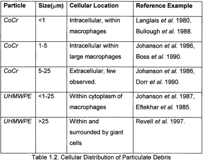
In 1951, Newman and Scales appreciated that the response of the macrophages was dependent on the particle size (The table below summarises the type, size, and cellular location of CoCr and polyethylene particulate debris with a reference example).
Particle Slze(pm ) Cellular Location R eference Exam ple
CoCr <1 Intracellular, within macrophages
Langlais ata l. 1980, Bullough a ta l. 1988.
CoCr 1-5 Intracellular within large macrophages
Johansen atal. 1986, Boss a ta l. 1990.
CoCr 5-25 Extracellular, few observed.
Johansen a ta l. 1986,
Dorr a ta l. 1990.
U H M W P E <1-25 Within cytoplasm of
macrophages
Johansen ata l. 1987, Eftekhar ef a/. 1985.
U H M W P E >25 Within and
surrounded by giant cells
Revel 1 at al. 1997.
Table 1.2. Cellular Distribution of Pari iculate Debris
Within normal remodelling there is ongoing formation and resorption of bone. The cell responsible for usual bone resorption is the osteoclast. This large multi-nucleated cell, with its “ruffled-border” is often located at the tip of a resorption wedge. Its features are well reported (Gothlin and Ericsson 1976, Chambers 1980, Teitelbaum 1993, Athanasou et al.
1996). Osteoclasts are related to the same stem cells of the monocyte-macrophage lineage.
Cells in the tissue layers at the implant interfaces have been found to contain potent osteolytic factors (Jiranek at al. 1993, Chiba at al. 1994, Goodman at al. 1997), including Interleukin 1 (IL-1), Interleukin 6 (IL-6), (Gowen atal. 1983, Stashenko ata l. 1987, Herman at al. 1989, Al-Safar and Revel I 1994, Westacott at al. 1992), Tumour necrosis factor-a, (TN F-a) also named Osteoclast activating factor, (OAF) (Bertolini at al.
1986, Beezhold at al. 1989, Pfeilschifter at al. 1989, Algan at al. 1996, Hicks at al. 1996), as well as various oxide radicals (Hukkanen at al.
1997 and 1998), matrix metalloproteinases (Takagi at al. 1998), and hydrogen peroxide (Kossovsky at al. 1991). These are secreted by fibroblasts, endothelial cells, and macrophages. OAF is largely secreted by macrophages.
The macrophage can be “activated” into further macrophage recruitment, phagocytosis, and the release of osteoclastic factors, by particulate debris, bacteria, and cell death. These factors proceed to stimulate osteoclastic mediated bone resorption (Murray and Rushton 1990, Rood man 1993).
Not only are osteoclasts capable of bone resorption but macrophages may also have an ability for bone resorption directly (Mundy et al. 1977, MacArthur et al. 1980, Santavirta et al. 1990, Kossovsky et al. 1991, Athanasou et al. 1992, Quinn et al. 1992, Lassus et al. 1998). Direct enzymatic degradation of bone is also significant in joint loosening (Hukkanen eta l. 1997).
1.10 TH E ROLE OF M ICROM OTION
Aseptic loosening is not wholly attributed to the action of wear particles. The lack of mechanical integrity of prostheses is significant in the aetiology of loosening (Clarke 1990, Freeman and Plank-Bordeneuve 1994, Karrholm et al. 1994, W alker et al. 1995). The maintenance and possible proliferation of a soft tissue membrane inter-posing the implant-bone interface may be attributable to micromotion (Aspenberg
et al. 1992, Soballe et al. 1992, Goodman 1994). Experimentally the
role of micromotion in the sensitisation for subsequent cell mediated bone lysis has been postulated (Goodman et al. 1995, Aspenberg and Herbertsson 1996).
1.11 TH E HYPOTHESES AND THESES FORMAT
In summary, localised radiolucencies at the bone-cement interface represent loosening and subsequent pain, necessitating revision surgery. These points of focal osteolysis are caused by wear particles at the interfaces. If they can be prevented from reaching the interfaces, wear debris induced osteolysis will not occur. The proposed method to prevent migration of the particles is to attach a custom made, flexible, osteopromotive e-PTFE GORE-TEX® membrane to the implant and bone, as illustrated in figure 1.1
Prototype e-P T F E
m em brane, that
forms primary
mechanical seal.
Dead space into which
bone growth occurs,
forming secondary
biological seal.
1.12 TH E CO N CEPT OF GUIDED TISSUE REGENERATION
The concept of mechanically sealing off a specific anatomical site for improving the healing of a particular tissue type began in the 1950s, for neural tissue (Campbell and Bassett 1953) and spinal bone applications (Hurley e ta l. 1959).
Much of the modern work into Guided Tissue Regeneration (GTR) has been performed in the field of periodontology, a branch of dentistry concerned with the tissues of the gingiva, periodontal membrane, alveolar bone and cementum that support and attach the teeth. An example of how GTR can be used is demonstrated below in the treatment of periodontis.
1.12.1 A Periodontological Example of Guided Tissue Regeneration There are substantial changes to the tooth root surface following periodontitis. The normal root is rich in collagen connecting to the adjacent bone. These can be destroyed by plaque induced inflammation, causing down-growth of the surrounding epithelium, exposing the root surface to the periodontal pocket and oral environment.
Following bacterial penetration, the root surface becomes toxic and unsuitable for the new connective tissue attachment required for regeneration. Having thoroughly debrided the site, only periodontal cells growing coronally will restore the fibre and cementum network, (Karing
After surgery the periodontal ligament cells are prevented from migrating over the wound surface adjacent to the root by the dentogingivial epithelial cells, which forms a long junctional epithelium thus preventing any new functional attachment. If the cells of the periodontal ligament are guided correctly, they can become established on the root surface, forming a fresh attachment provided they are isolated from the other tissues during healing (Dahlin et al. 1988).
Membranes are used to isolate tissue types over engineered defects to prevent unwanted cells accessing the site. Normally the gingival crestal fibres insert onto the cementum on the tooth surface creating a barrier thus inhibiting epithelial migration (Winter 1974). This was termed ‘contact inhibition’ and it was inferred that the connective tissue attachment to a porous biomaterial provided a similar function as collagen fibres that insert into the cementum of the tooth. Without this connective tissue attachment, the surrounding epithelium forms a sinus tract and isolates the implant, causing the material to extrude from the tissue (Robinson and Daly 1980).
The subset of Guided Tissue Regeneration relevant to this work, is Guided Bone Regeneration (GBR). Much of the work into osseointegration using GBR has been performed in the field of Implant Dentistry to replace lost or missing teeth in fully and partially edentulous patients. Major contributors to the knowledge of Guided Bone Regeneration in Implant Dentistry’ have compiled their experiences, in a book of the same title (Buser et al. 1994).
1.13 G UIDED BONE REGENERATION A HISTORICAL PERSPECTIVE It will be demonstrated that the most critical issue for facilitating guided bone regeneration is the maintenance of a space, into which osseo-genesis can occur. This fact was appreciated as early as 1947, by Atle Berg, who hypothesised that osteogenesis in the spine was achievable, if the paraspinal muscles were elevated from decorticated laminae using bone grafts. The orientation of bone into a particular site was conducted in the 1950’s (Hellstadius 1950, Murrey at ai. 1957). Arvid Hellstadius tested Berg’s theory by using stainless steel cups and rings to raise soft tissues from the roughened cortex of rabbit femora to provoke osteogenesis.
In 1957 Murrey realised that the three critical factors needed for new bone growth were (1) adequate vascularity, (2) osteogenic cells adjacent to the defect and (3)“contact with living tissue.” To this end he protected a blood clot with a fenestrated cage. No indication was given to the fenestration size. The clot eventually filled with bone. No histological investigations were undertaken and hence the cellular activities were not known. In another study, a polyethylene tube filled with a blood clot and autogenous cancellous graft was able to bridge a
Melcher and Dreyer (1962) protected a blood clot containing bone defect, with either a plastic or organic shield, and found that the haematoma boundaries determined the size of the subsequent bone. The bone only formed if non-osteogenic cells were excluded from the
haematoma site.
Bassett et al. (1961) and Bassett (1964) investigated the source and regulation of osteogenesis. The use of membranes for augmenting bone growth was first studied by Boyne and Mikel during the 1960s, using Millipore filters (Boyne 1964, Boyne and Mikel 1968). Placement of barrier membranes in direct contact with the outer cortical bone prevented the ingrowth of fibrous connective tissue into the bone
defects.
A space was needed between the barrier and mechanically stable bone surface for a successful result. In the early 1980s this principle was used in periodontology for guided tissue regeneration discussed in the previous example. The use of e-PTFE as an osteopromotive membrane was becoming apparent (Scantlebury 1993).
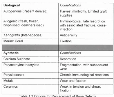
1.13.1 The Replacement of Bony defects
Biological Complications
Autogenous (Patient derived) Harvest morbidity. Limited graft
supplies
Allogenic (fresh, frozen, lyophilised, demineralised)
Immunological, late resorption with associated fracture, cross infection
Xenografts (Inter-species) Antigenicity
Marine Coral Fixation
Synthetic Complications
Calcium Sulphate Resorption
Polymethylmethacrylate Fragmentation, with subsequent
wear
Polysiloxanes Chronic immunological reactions
Metals Wear and fixation
Ceramics Weak in tension and shear,
fixation
Table 1.3 Options for Rep acement of Bone Defects
Specific substitute materials have been reviewed (Hanft et al. 1995). Do
Novo, host bone would be the ideal replacement for defects. This was
exemplified by the llizarov technique for Transosseous Osteosynthesis
(llizarov 1991). The methodology was the controlled distraction of bone
fragments, at a rate that allows inter-fragmentary bone formation,
without consolidation. Moreover this prevented soft tissue ingression
between the bone edges, but permitted further osteogenesis as the
fragments were distracted. The techniques of this practice have been
classified and reviewed (Yaszemski et ai. 1996, Tsuchiya et al. 1997,
Yasui etal. 1997).
It is apparent that bone has an intrinsic ability to regenerate if assisted
1.14 TH E BIOLOGICAL BASIS FOR G UIDED BONE REGENERATION Bone is a complex and diverse tissue and has been characterised both macroscopically and histologically (Hall 1991, Soames 1995). ‘Regenerate’ is defined as “bring or come into renewed existence.” Physiological regeneration involves an ongoing replacement of tissues, typical of a normal continual metabolic process. A description of basic physiological bone regeneration or turnover has been described (Hall 1991). Reparative regeneration replaces injured or pathological tissues. If this reparative regeneration is engineered, it becomes guided bone regeneration. A basic appreciation of the biology of bone regeneration in this context is critical in the planning of surgical procedures. This will enable the creation of the environment most conducive for de novo
osteogenesis.
Hence the three fundamental stipulations for bone growth are: 1. Local presence of bone forming cells, osteoblasts.
2. Ample local blood supply.
3. Mechanical support and the maintenance of space into which the osteoblasts can proliferate.
The mechanical support and the maintenance of space modulates guided bone regeneration. This determines the success of bone regeneration, which is dependent on the first two stipulations.
Johner (1977) examined the healing of holes in the tibia of rabbits. Hole diameters between 0.1 and 1mm were selected; 0.2mm diameter holes filled with lamellar bone concentrically. For holes up to 1mm, a scaffold
of woven bone is deposited over the defect and lamellar bone is
deposited in the newly formed intertrabecular spaces in a ‘matter of days' (Schenk and Willenger 1977). This applies to defects circumferentially surrounded completely by bone. If only one surface is bone, and the other biomaterial, spontaneous repair sizes do differ.
Another essential factor for bone formation is stability. The presence of micromotion distorts any perceived values of critical size defects at which spontaneous bone healing will take place. Harris et al. (1983) demonstrated that for an uncemented acetabular cup in a dog, a gap of 0.5mm could not be bridged by bone, leaving a fibrous tissue envelope.
14.1.1 Critical Size Defects and Non-Union
In any discussion of bone repair an appreciation of the critical size defect (OSD) is essential (Hollinger and Kleinschmidt 1990). Schmitz and Hollinger (1986) described the OSD as “The smallest size intraosseous wound in a particular bone and species of animal, that will not heal spontaneously during the lifetime of the animal.” However this is not a constant value but dependent on species, site, age, and soft tissue involvement.
Bony union will not occur, without assistance, for defects beyond the CSD. Other factors can also cause bony non-union, even if the defects are within the critical size, such as instability, periosteal disruption, interposition of soft tissue, infection, inadequate vascularity, as well as nutritional and metabolic alterations (Mathog and Boies 1975, DeChamplain 1973).
For even larger defects, methods for aiding regeneration are required. This is achieved by providing a scaffold to allow cellular colonisation and integration. Analogous with the ‘race for the surface’ between host cells and bacteria proposed by Gristina (1987), as a subset response from the host tissues there exists a further “race”.
Ogiso et al. (1991) showed in vitro that fibroblasts produce one or more soluble factors that have a deleterious effect on bone stem cell differentiation and osteogenesis. Schmitz et al. (1990), proposed that in the absence of appropriate bone derived augmentation and specific growth factors in large defects, cells are unable to differentiate into osteoblasts and to calcify the matrix. It is clear that the role of the osteogenic stem cell and the stromal system of bone and marrow is essential (Beresford 1989).
Obviously orthopaedic practice is not only concerned with bony defects. As discussed previously, the treatment of joint disorders is also an extremely relevant and critical issue. The complete incorporation of orthopaedic implants working symbiotically with the body is a goal yet to be fully realised.
1.14.2 History of Osseo-lntegration
These implants have had long-term follow-up (Adell et al. 1981 & 1987), with a survival rate of 86% in the mandible and 78% in the maxilla. These and other positive survivorship figures from fully (Babbash at al.
1986, Bruggenkate at al. 1990) as well as partially edentulous patients (Buser at al. 1991, Zarb and Schmitt 1993a&b), widened the scope for patient selection.
Patients presenting with equivocal indications such as recipient sites without sufficient bone, sites in the locality of specific anatomical structures (mandibular nerves, maxillary sinus, nasal cavity) extraction sockets, and high-demanding aesthetic results became candidates for treatment consideration, with new Guided Bone Regenerative technologies.
1.15 EXPANDED POLYTETRAFLUOROETHYLENE (e-PTFE)
Fluorocarbons are generally very stable compounds. PTFE is produced from tetrafluoroethyiene which in turn is produced from the fluorination of trichloromethane.
Host responses cannot chemically react with the densely fluorinated carbon chain, hence the material is accepted and tissues continue to undergo a healthy turnover. The e-PTFE membrane has been shown to provoke an inflammatory response that is slightly more intense than a sham operation (Lam et al. 1995).
The aforementioned property of osteopromotive' is an index of the proliferative ability of bone, given the correct environment. e-PTFE is chemically able to provide this environment by being so inert as to not provoke a chemical response. However it does show a very high water contact angle, defining e-PTFE as a highly hydrophobic material (Lam
e ta l. 1995).
e-P TFE is a three dimensional matrix of nodes and interconnecting fibrils. The material elicits a similar response when implanted into different sites, with encapsulation and cell colonisation (Béllon et al.
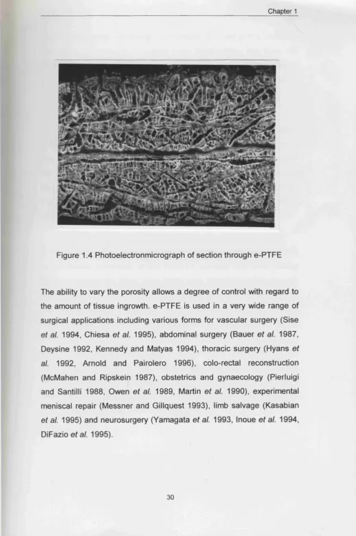
Figure 1.4 Photoelectronmicrograph of section through e-PTFE
The ability to vary the porosity allows a degree of control with regard to the amount of tissue ingrowth. e-PTFE is used in a very wide range of surgical applications including various forms for vascular surgery (Sise
et al. 1994, Chiesa et al. 1995), abdominal surgery (Bauer et al. 1987, Deysine 1992, Kennedy and Matyas 1994), thoracic surgery (Hyans et al. 1992, Arnold and Pairolero 1996), colo-rectal reconstruction (McMahen and Ripskein 1987), obstetrics and gynaecology (Pierluigi and Santilli 1988, Owen et al. 1989, Martin et al. 1990), experimental meniscal repair (Messner and Gillquest 1993), limb salvage (Kasabian
e-P TFE has a long history in implant density. The use of this particular material is not requisite for guided bone regeneration, and there are other membranes that can function within this context (Kleinschmidt et al. 1993, Sandberg at al. 1993, Ashammakhi at al. 1995, Zellin at al.
1995, Piatelli a ta l. 1996, Pineda atal. 1996).
For guided bone regeneration the membrane should be biocompatible, occlusive to cells but not fluids, have the structural integrity to form a ‘space’, allow tissue ingrowth hence stability, and be clinically manageable (Hardwick at al. 1994). e-P TFE has the longest experimental record in guided bone regeneration. It has been shown that membranes constructed of different materials vary considerably in osteopromotive efficacy (Zellin at al. 1995).
In 1988 Dahlin at al. used expanded polytetrafluoroethylene (e-PTFE) as the barrier membrane’ to test the GTR principle with GBR. Having lifted mucoperiosteal flaps, 5mm holes were drilled bilaterally through the mandibles of 30 dogs. Controls had defects that where covered by just the mucoperiosteal flap, and the test sites had e-P T F E membranes (W.L. Gore and Associates, Flagstaff, Arizona) placed over the defects, prior to flap coverage and wound closure. Histomorphometric and gross analysis showed that the control defects were filled with fibrous connective tissue with a slight ingrowth of new bone at the defect margins whereas the test groups demonstrated new complete bone regeneration. Hence following further testing (Dahlin at al. 1990, Seibert
Dahlin (1993) used (^H) thymidine as a bone marker in rats. Ten days after surgery, endosteal cells within the bone adjacent to the membrane defects were undergoing mitosis. Incorporation of ^®Ca showed that test defects had a significantly higher quantity of mineralisation, even though the rate of uptake was slower. Maximal levels were reached after five weeks in the test specimens and two weeks in the controls. In rats, the potential for osteogenesis is high and so the rate of bone formation would be slower in man (Schmitz et al. 1986).
Linde (1993a) showed the osteopromotive effect of e-PTFE membranes can also cause bone to grow in anatomical sites where ordinarily bone is absent. He used a stiff dome-shaped material placed on top of the flat calvarium of rats, forming a sealed space into which osteogenic cells could migrate. The establishment of a blood clot beneath the membrane into an actual space is of paramount importance in allowing predictable osteogenesis. This study used a very porous form of e-PTFE, with 100pm pores, which also allowed angiogenesis. Moreover bone formation was also seen outside the membrane.
The variation in pore size and the ability of neovascularisation has been investigated (Brauker et al. 1995). Results suggest that larger pore diameters are able to support vascularisation by allowing cell entry.
Osteogenic cell origin is important, in aiding their migration and proliferation. In fractures, the cells derive from the periosteum and marrow. Under the defect, cell recruitment arises mostly from the endosteum, as well as from Haversian and Volkmann canals.
1.16 PRACTICAL ASPECTS OF GU ID ED BONE REGENERATION The maintenance of a ‘space-making site’ is essential, and failure to make provision for this results in failure of GBR (Dahlin et al. 1988 & 1989, Melcher and Dreyen 1962, Seibert and Nyman 1990, Kohavi et ai.
1991). This is often the case when implants are placed in areas surrounded by inadequate bone volume such as dehiscence defects, cartilage fenestration defects or residual intraosseous defects.
For acceptable results, a defined, stable region into which bone is intended to grow during healing must be created and maintained for a sufficient period of time. Bone regeneration in membrane treated periodontal defects in dogs, is a function o f the amount o f space available (Haney et al. 1993).
The contours of new bone are defined by contours of the membrane boundaries (Kohavi et al. 1991). However, the membrane cannot be too stiff, as this reduces its adaptability to the surfaces to which it is attached. An added value of stiffness is the ability for the membrane to have a degree of memory' to the surface contours.
Membrane collapse into the space can be prevented using a scaffold, or filler. A collagen sponge (Collagen Fleece, Pentapharm AG, Basel, Switzerland) has been used (Buser at al. 1994) under membranes to secure a blood clot in the bone defect. It is used in conjunction with supporting screws to elevate the membrane since the collagen sponge cannot support the membrane solely.
Alternatively autogenous bone graft provides an excellent potential for neo-osteogenesis. This can be stabilised by the injection of intravenous blood to provide a scaffold for bone formation, analogous to fracture repair.
Fixation techniques, for accurate membrane placement in dental applications, include cover screws as well as stainless steel mini fixation screws (Schenck et a i 1994). These devices also facilitate radiographic membrane location and were based on mini-screws used for bone fragment stabilisation in maxillofacial surgery. They have been specifically modified for membrane placement (Memfix System, Institute Straumann AG, Waldenburg, Switzerland).
There remain a number of different methods for membrane attachment, including standard sutures (Dahlin et a i 1988). In some cases the sutures themselves have been made of e-PTFE (Linde and Hedner 1995, Zellin et a i 1995). Reinforcement with e-P TFE rings has also been used (Nyman et a i 1995). Common membrane attachment appears to be by press-fit placement with further support and coverage from the local periosteal flap (Nyman et a i 1990, Linde et a i 1993, Piatelli et a i 1996).
For membrane attachment on both the femoral and acetabular sides there is an inherent lack of congruent surfaces, albeit more so in the former. It is absolutely essential to ensure direct e-PTFE-bone contact in order to reduce the likelihood of soft-tissue encroachment. Rigid fixation avoids the entrapment of the membrane within the articulation.
The attachment method that proved most feasible and fulfilled the above criteria was the use of a biocompatible butyl-cyanoacrylate adhesive.
1.17 TH E USE OF BUTYL-CYANOACRYLATE ADHESIVE
Cyanoacrylate have been used experimentally and clinically for decades as a tissue adhesive as well as a haemostatic and embolic agent (Awe eta l. 1963, Orda e ta l. 1974, Vinters eta l. 1985).
N-Butyl-2-cyanoacrylate is biocompatible and resorbable (Reynolds et al. 1966, Pani et ai. 1968). The cyanoacrylates are degraded and excreted in urine (Reynolds et ai. 1966). The most common and widely used application of the cyanoacrylate is for the closure of superficial skin lacerations, especially in children (Gahl et ai. 1984, Morton et al.
1988, Mizrahi et al. 1988, Watson 1989 Applebaum et al. 1993, Quinn
et al. 1993, Vobel et al. 1993). Its also has been shown to have a
degree of bacteriostatic action (Howell et al. 1995).
There are a variety of formulations available although Histoacryl Blue® (B.Braun, Melsungen AG) is the most widely used in the clinical setting. Histoacryl Blue® is supplied in 0.5ml plastic vials, in boxes of 5. The monomer contains a dye, 1 -hydroxy-4-p-touidion-antrachion that imparts a blue appearance making it clearly visible in the surgical field. It is applied using a fine plastic nozzle although an aerosol has also been utilised (Quillen and Rosenwater 1994).
Complications of its use include exothermic liberation, and a quick setting time of 20 seconds, thereby not permitting tissue replacement. It also has a lack of tensile strength relative to sutures (Bresnahan et al.
1995).
As well as dermatological applications the cyanoacrylates are also used for deeper tissue applications, including bony repair of the cranium (Amarante et al. 1995) or the appendicular skeleton (Capasso et al.
1.18 THE GOAL
The specific goal is to apply the techniques of GBR in the prevention of loosening of total hip replacements.
C h ap ter 2 Biocompatibility and the
In Vitro
properties of
e-P TFE and Butyl-cyanoacrylate Adhesive
2 .1 1ntroduction
2.2 Materials and Methods
2.3 Results
2.4 Discussion
2.1 Introduction
Our aim was to establish the in vitro biocompatibility of e-PTFE combined with butyl-cyanoacrylate on a human-osteosarcoma cell line. In vivo
experimentation has traditionally followed in vitro screening. Osteoblast-like cells were selected since the biomaterial/bone interactions were critical in determining the guided bone regenerative capacity of the initial seal.
In vitro systems have been used widely for biomaterial testing (Johnson et
al. 1985, Kirkpatrick and Mittermayer 1990, Vince et al. 1991, Hunter et al.
1995, Morrison et al. 1995). The greatest benefit of in vitro testing is the ability to control and define specific criteria and compare their relative contributions to the biological system being analysed. However, the most important shortcoming is the lack of circulatory and lymphatic systems for both the removal of harmful products and the nourishment of the cells in situ.
The primary objective of the study was to characterise the mitogenic effect of butyl-cyanoacrylate and e-PTFE using the HOS cell line TE85. These were obtained from the European Collection of Animal Cell Cultures (ECACC No. 87070202), and were used between passages 6 and 12 in all experimentation. The HOS cell line has a consistent reproducibility and a rapid turnover rate, yielding large cell numbers for subsequent assays. It is appreciated that larger bone in vitro studies ought to evoke the use of primary osteoblasts, since proliferation and alkaline phosphatase activity of HOS cell lines cannot be directly correlated (Clover and Gowen 1994). Nevertheless, the HOS data provides an indication of how the particular biomaterial affects the relative proliferation rates.
Proliferation was quantified using [^H] thymidine incorporation per microgram of DNA. Cells in the S-phase take up 3H-thymidine for incorporation into newly synthesised DNA. The limitations of this method have been detailed by Maurer (1981), and these include radiochemical impurities in [^H] thymidine, incorporation into RNA, protein and lipid fractions as well as the DNA, and the possibility that labelled thymidine may affect the structural integrity of DNA. Therefore, results drawn from such experimentation should be interpreted cautiously. However, Maurer does acknowledge that these artefacts' may be of varying significance and should be considered with respect to individual cases. Despite these shortcomings, thymidine incorporation is still used to quantify cellular proliferation (Hunter et al. 1992). W e accept that for a more detailed in vitro
2.2. Materials and Methods 2.2.1. Elution Test.
An international standard designed specifically for the biological evaluation of medical devices has been established. Method criteria determining in vitro
testing for cytotoxicity have been followed as defined by Part 5 of ISO 10993-5. In the first stage of this investigation we studied the incubation of cultured HOS TE85 cells with serum extracts of porous e-PTFE, butyl-cyanoacrylate, reagent control and an organo-tin stabilised poly(vinylchloride) toxic positive control.
2.4.2 Cell Seeding Test
Cell growth was tested on the following biomaterials, and their combinations: (1) 5 mm Thermanox discs (Life Technologies), as the control surface, (2) a sterile silicon medical adhesive type A (Silastic®, Cat. No. 891, Dow Corning Corporation, Medical Products 1051393-0390, Ml. 48640, U.S.A), (3) the butyl-cyanoacrylate (Vetbond™, 3M, No. 1469, St. Paul, MN 55144-1000), (4) e-P TFE (W.L. Gore and associates. Flagstaff, Arizona), (5) e-PTFE glued to the base of the well by silicon glue, and (6) e-P TFE glued to the base of the well by the butyl-cyanoacrylate. Cells were seeded as in the first test. e-P TFE is extremely hydrophobic and floats on water. Therefore to allow cell attachment for the culture of e-P TFE only, the volume was halved and the cell concentration was doubled. This formed a large drop over the e-P TFE surface and prevented the membrane from floating, thus allowing the cells to attach whilst in media.
2.3 RESULTS 2.3.1 Elution Test
After the initial 24 hours, and before the extractant was added, microscopic visualisation (Olympus 1X70) during culture demonstrated that some of the cells had attached to the tissue culture plastic well base, but they were not confluent.
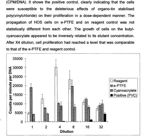
Figure 2.1 demonstrates the Counts per minute divided by the mass of DNA (CPM/DNA). It shows the positive control, clearly indicating that the cells were susceptible to the deleterious effects of organo-tin stabilised poly(vinylchloride) on their proliferation in a dose-dependent manner. The propagation of HOS cells on e-P TFE and on reagent control was not statistically different from each other. The growth of cells on the butyl-cyanoacrylate appeared to be inversely related to its elutant concentration. After X4 dilution, cell proliferation had reached a level that was comparable to that of the e-PTFE and reagent control.
35000 < 30000 z
Û
fe 25000 Q.
^
20000
c E 15000 V Q.
1
10000
3O 5000
E3
□ Reagent H e-PTFE n Cyanoacrylate
Positive (PVC)
4 8
Dilution
2.3.2 Cell seeding
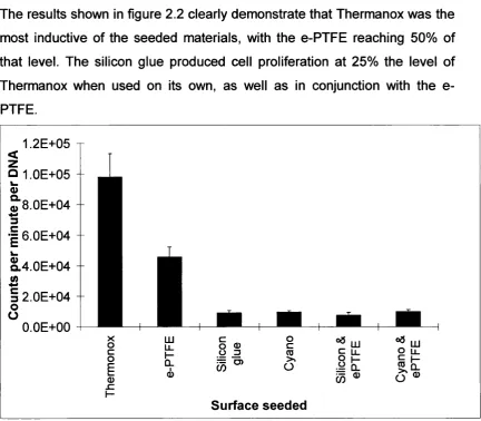
The results shown in figure 2.2 clearly demonstrate that Thermanox was the most inductive of the seeded materials, with the e-P TFE reaching 50% of that level. The silicon glue produced cell proliferation at 25% the level of Thermanox when used on its own, as well as in conjunction with the e-PTFE.
1.2E+05
<
z
O 1 OE+05 Q) O. 0) 8.0E+04 3 ■g 6.0E+04 O.4.0E+04
JS
c
o o 2.0E+04 O.OE+00 g c o É (D sz 01
«3 liJIt
0) ^
lil
ro s:
o
Surface seeded