IJIRT 144771
INTERNATIONAL JO URNAL OF INNOVATIVE RESEARCH IN TECHNOLOGY134
Simulation of an Improved Active Power Filter
Performance for Renewable Power Generation
systems
S.Shivaprasad
1, M.Saikumar
2M.Tech student P.E, SR Engineering College, Warangal, Telangana, India
Assistant professor, EEE, SR Engineering College, Warangal, Telangana, India
Abstract-This paper represents an active power filter
implemented with a four-leg voltage-source inverter using a predictive control scheme is presented. Here the
active power filterisusedto reduce the current
harmonics. Generated from the load. The load nothing but non-linear load .S o we are eliminating the current harmonics generated from the load. The effective solution to eliminating the current harmonics are the active power filters is derived and used to design the predictive control algorithm. . The compensation performance of the proposed active power filter and the associated control scheme under steady state and transient operating conditions is demonstrated through simulations and experimental results.
I. INTRODUCTION
The increasing energy demand, increasing costs and exhaustible nature of fossil fuels, and global environment pollution have generated huge interest in renewable energy resources. Other than hydroelectric power, wind and solar are the mos t useful energy sources to satisfy our power requirements. Wind energy is capable of producing huge amounts of power, but its availability can’t be predicted. Solar power is available during the whole day but the solar irradiance levels change because of the changes in the sun’s intensity and shadows caused by many reasons. Generally solar and wind powers are complementary in nature. Therefore the hybrid photovoltaic and wind energy system has higher dependability to give steady power than each of them operating individually. Other benefit of the hybrid system is that the amount of the battery storage can be decreased as hybrid system is more reliable compared to their independent operation. Although active power filters implemented with three-phase four-leg voltage-source inverters (4L-VSI) have already been presented in the technical literature, the primary contribution of this paper is a
predictive control algorithm designed and
implemented specifically for this application .Traditionally, active power filters have been controlled using pre tuned controllers, such as PI-type or adaptive, for the current as well as for the dc-voltage loops. PI controllers must be designed based on the equivalent linear model, while predictive controllers use the nonlinear model, which is closer to real operating conditions. An accurate model obtained using predictive controllers improves the performance of the active power filter, especially during transient operating conditions, because it can quickly follow the current-reference signal while maintaining a constant dc-voltage.
So far, implementations of predictive control in power converters have been used mainly in induction motor drives. In the case of motor drive applications, predictive control represents a very intuitive control scheme that handles multivariable characteristics, simplifies the treatment of dead-time compensations, and permits pulse-width modulator replacement. However, these kinds of applications present disadvantages related to oscillations and instability created from unknown load parameters. One advantage of the proposed algorithm is that it fits well in active power filter applications, since the power converter output parameters are well known. These output parameters are obtained from the converter output ripple filter and the power system equivalent impedance. The converter output ripple filter is part of the active power filter design and the power system impedance is obtained from well-known standard procedures. In the case of unknown system impedance parameters, an estimation method can be used to derive an accurate R–L equivalent impedance model of the system.
IJIRT 144771
INTERNATIONAL JO URNAL OF INNOVATIVE RESEARCH IN TECHNOLOGY135
proposed predictive control scheme, including the design procedure. The complete description of the selected current reference generator implemented in the active power filter is also presented.
Fig 1. Stand-alone hybrid power generation system with a shunt active power filter
Fig.2. Three-phase equivalent circuit of the proposed shunt active power filter
Control scheme compensation are demonstrated through simulation and validated with experimental results obtained in a 2 KVA laboratory prototype.
II. FOUR-LEG INVERTER MODEL
Fig.1. shows the configuration of a typical power distribution system with renewable power generation. It consists of various types of power generation units and different types of loads. Renewable sources, such as wind and sunlight, are typically used to generate electricity for residential users and small industries. Both types of power generation use ac/ac and dc/ac static PWM converters for voltage conversion and battery banks for long-term energy storage. These converters perform maximum power point tracking to extract the maximum energy possible from wind and sun. The four-leg PWM converter topology is shown in Fig.2.This converter topology is similar to the
conventional three-phase converter with the fourth leg connected to the neutral bus of the system. The fourth leg increases switching states, improving control flexibility and output voltage quality, and is suitable for current unbalanced compensation.
Fig. 2.1. Two-level four-leg PWM-VSI topology
III.DIGITA L PREDICTIVE CURRENT CONTROL
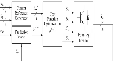
The block diagram of the proposed digital predictive current control scheme is shown in Fig. 3.1. This control scheme is basically an optimization algorithm and, therefore, it has to be implemented in a microprocessor. Consequently, the analysis has to be developed using discrete mathematics in order to consider additional restrictions such as time delays and approximations
Fig. 3.1. Proposed predictive digital current control block diagram.
IJIRT 144771
INTERNATIONAL JO URNAL OF INNOVATIVE RESEARCH IN TECHNOLOGY136
1) CURRENT REFERENCE GENERATOR
This unit is designed to generate the required current reference that is used to compensate the undesirable load current components. In this case, the system voltages, the load currents, and the dc-voltage converter are measured, while the neutral output current and neutral load current are generated directly from these signals (IV).
2) PREDICTION MODEL
The converter model is used to predict the output converter current. Since the controller operates in discrete time, both the controller and the system model must be represented in a discrete time domain. The discrete time model consists of a recursive matrix equation that represents this prediction system. This means that for a given sampling time Ts, knowing the converter switching states and control variables at Instant kTs, it is possible to predict the next states at any instant [k+1]Ts. Due to the first-order nature of the state equations that describe the model in (1)–(2), a sufficiently accurate first-order approximation of the derivative is considered in this paper
(1)
The 16 possible output current predicted values can be obtained from (2) and (4) as
(2)
As shown in (5), in order to predict the output current i at the instant (k+1), the input voltage value vo and the converter output voltage vxn, are required. The algorithm calculates all 16 values associated with the possible combinations that the state variables can achieve.
3) COST FUNCTION OPTIMIZATION
In order to select the optimal switching state that must be applied to the power converter, the 16 predicted values obtained for io[k+1]are compared with the reference using a cost function, as follows:
4). CURRENT REFERENCE GENERTION
A dq-based current reference generator scheme is used to obtain the active power filter current reference signals. This scheme presents a fast and accurate signal tracking capability. This characteristic avoids voltage fluctuations that deteriorate the current reference signal affecting compensation performance [28]. The current reference signals are obtained from the corresponding load currents as shown in Fig. 3.2. This module calculates the reference signal currents required by the converter to compensate reactive power, current harmonic and current imbalance. The displacement power factor (sinφ (L)) and the maximum total harmonic distortion of the load (THD (L)) defines the relationships between the apparent power required by the active power filter, with respect to the load.
The dq-based scheme operates in a rotating reference frame; therefore, the measured currents must be multiplied by the sin (wt) and cos (wt) signals. By using dq-transformation, the d current component is synchronized with the corresponding phase-to-neutral system voltage, and the q current component is phase-shifted by 90◦.The sin (wt) and cos (wt) synchronized reference signals are obtained from a synchronous reference frame (SRF) PLL [29]. The SRF-PLL generates a pure sinusoidal waveform even when the system voltage is severely distorted.
Fig. 3.2 D q-based current reference generator block diagram
IJIRT 144771
INTERNATIONAL JO URNAL OF INNOVATIVE RESEARCH IN TECHNOLOGY137
components (id and iq) .One of the major advantages of the dq-based current reference generator scheme is that it allows the implementation of a linear controller in the dc-voltage control loop. However, one important disadvantage of the dq-based current reference frame algorithm used to generate the current reference is that a second order harmonic component is generated in id and iq under unbalanced operating conditions. The amplitude of this harmonic depends on the percent of unbalanced load current (expressed as the relationship between the negative sequence current iL,2 and the positive sequence current iL,1). The second-order harmonic cannot be removed from id and iq , and therefore generated.
IV. EXISTING MATLAB/SIMULINK MODEL
Fig 4.1 Existing Mat lab/Simulink Model
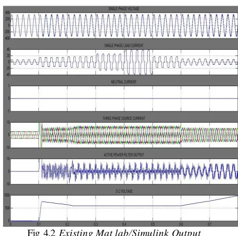
MATLAB/SIMULINK OUTPUT
Fig 4.2 Existing Mat lab/Simulink Output
V.CONCLUSION
Improved system performance is observered after the introduction of P.V module as an input to active
power filter which includes the compensation of reactive power, and current harmonics by numerically reducing the total harmonic distortion of the source current from 30% to 6% on average. Resulting in surge of the quality of power in distribution system to a good extent. The predictive algorithm is proved a better alternate to conventional converters in handling non linear and unbalanced load because of its simplicity.
REFERENCES
[1] Improved Active Power Filter Performance for Renewable Power reneration Systems. IEEE
TRANSACTIONS ON POWER
ELECTRONICS, VOL. 29, NO. 2,FEBRUARY 2014
[2] J. Rocabert, A. Luna, F. Blaabjerg, and P. Rodriguez, “Control of power converters in AC microgrids,” IEEE Trans. Power Electron., vol. 27, no. 11, pp. 4734–4749, Nov. 2012.
[3] M. Aredes, J. Hafner, and K. Heumann, “Three-phase four-wire shunt active filter control strategies,”IEEE Trans. Power Electron., vol. 12, no. 2, pp. 311–318, Mar. 1997.
IJIRT 144771
INTERNATIONAL JO URNAL OF INNOVATIVE RESEARCH IN TECHNOLOGY138
converter,”Gener. Transm. Distrib., IET, vol. 3, no. 5, pp. 437–447, May 2009.
[5] N. Prabhakar and M. Mishra, “Dynamic
hysteresis current control to minimize switching for three-phase four-leg VSI topology to compensate nonlinear load,” IEEE Trans. Power Electron., vol. 25, no. 8, pp. 1935– 1942, Aug. 2010.
[6] V. Khadkikar, A. Chandra, and B. Singh, “Digital signal processor implementation and performance evaluation of split capacitor, leg and three h-bridge-based three-phase four-wire shunt active filters,” Power Electron., IET, vol. 4, no. 4, pp. 463–470, Apr. 2011.
[7] F. Wang, J. Duarte, and M. Hendrix, “Grid-interfacing converter systems with enhanced voltage quality for micro grid application; concept and implementation,” IEEE Trans. Power Electron., vol. 26, no. 12, pp. 3501– 3513, Dec. 2011.
[8] X. Wei, “Study on digital pi control of current loop in active power filter,” inProc. 2010 Int.Conf. Electr. Control Eng., Jun. 2010, pp. 4287–4290.
[9] R. de Araujo Ribeiro, C. de Azevedo, and R. de Sousa, “A robust adaptive control strategy of active power filters for power-factor correction, harmonic compensation, and balancing of nonlinear loads, ”IEEE Trans. Power Electron., vol. 27, no. 2, pp. 718–730, Feb. 2012.