190605-2323-IJMME-IJENS © October 2019 IJENS I J E N S
Effects of Different Processes on Mechanical
Properties of CFRP by RTM and VIP
Techniques
M.Y. Yuhazri1*, A. Zailinda2, M.H. Amirhafizan1, H. Sihombing3, S.T.W. Lau4 1Faculty of Mechanical and Manufacturing Engineering Technology,
2Faculty of Mechanical Engineering,
3Faculty of Technology Management and Technopreneurship,
Universiti Teknikal Malaysia Melaka, Hang Tuah Jaya, 76100 Durian Tunggal, Melaka, Malaysia
1*[email protected];1[email protected]; 2[email protected];3[email protected]
4Faculty of Engineering & Technology
Multimedia University, Jalan Ayer Keroh Lama, 75450 Bukit Beruang, Melaka, Malaysia
Abstract— There is a high demand of hinge bracket for aircraft spoilers from metallic to composite materials in aircraft industries. Therefore, new fabrications process studies to replace the current process. Moreover, the current fabrication processes are of tooling and production are expensive as well as high testing cost. Thus, studies present the effect of different number and orientation of woven carbon fiber layers in laminated composites (CFRP) system in mechanical properties. The composites were fabricated based on eight plies, 16 plies, 24 piles and 32 plies of woven carbon fiber layers. The same orientation of woven carbon fiber layer was fabricated using two different processes which are Resin Transfer Moulding Process (RTM) and Vacuum Infusion Process (VIP). The composites fabricated using both processes undergo tensile test and flexural test to evaluate the effect of different process fabricating the composites with a different number of woven carbon fiber layers. Based on the results, the best properties of composites based on the different fabricated process and number of woven carbon fiber layers can be proposed to replace the manufacturing process for hinge bracket for aircraft spoilers were obtained. The result from the experiment shows that 8CF/EP composites fabricated using VIP have 10.6 % higher in specific strength obtained from tensile test and 64.4 % higher in specific strength obtained from the flexural test. From this results of this study indicate that the composites with 8 plies of carbon fiber fabricated using VIP has a good tensile and flexural strength compared to composites fabricated using RTM and other different plies of carbon in the composite.
Index Term
—
different processes, carbon fiber reinforced plastic, resin transfer moulding, vacuum infusion process, mechanical properties.I. INTRODUCTION
Nowadays, composites are broadly applied in different fields, for example, aviation structures, and automotive parts. However, aeronautics industries require a high volume of composite production, which is the disadvantages of this procedure which requires high tooling cost and low flexibility to design changes. In aviation industries demonstrates high tech demand for composite manufacturing. The interest of composite materials in aircraft structures comes from the action to reduce fuel consumption in the commercial airlines such as Airbus and Boeing both have been challenged to
increase their usage of composite materials in their aircraft [1]. The performance of an aircraft mainly depends on the lightweight of component, so the design of an aircraft is impacted by the interaction of its functional necessity and its basic strength, stiffness, and life requirements.
There is a limitation for doing a smart design using metals, so to meet the requirements a better performing material which is composites material called carbon fiber reinforced plastic (CFRP) is explored for the usage in aircraft part [2]. Besides, currently, most of the existing aircraft parts are made of metals. According to [3] the global objective is to reduce to half the amount of fuel by 2020 and at least 70 % less by 2025 concerning the Boeing 777, which is one of the most efficient aircraft entirely made by carbon fiber. In aerospace industries requires high volume production, the compression moulding process produces low-cost parts but requires a high capital investment in presses, infrastructure, and tooling. Moreover, well-known limitations of synthetic fibers such as Kevlar, glass, and carbon to degrade upon disposal as well as high processing cost and harmful to the environment, has emerged natural fibers as a cost-effective substitute for synthetic fibers. However, one of the major drawbacks of natural fibers reinforced composites is their low impact strength compared to the synthetic fibers reinforced composites [4-7].
190605-2323-IJMME-IJENS © October 2019 IJENS I J E N S
and vacuum infusion process are the two processes that will be investigate and reviewed. The main objective for the RTM and VIP testing is to compare the strength of the carbon fiber laminate fabrication using the RTM and VIP process and to study the effect of different numbers of carbon fiber layer in laminate composite system on both tensile and flexural test performance.
RTM is a process which has a lot of advantages such as low tooling cost, good dimensional tolerances, possibility to mould high complex shape, and have a good surface finish on both sides of composites part. RTM moulding has proved to a viable and competitive technique for fabrication of large, complex and high-performance FRP composite materials [8], [13]. RTM process involves five important components which are resin and catalyst container, pumping unit, mixing chamber, resin injector, and mould.
VIP is a process that uses vacuum pressure to flow resin into a laminate. The material or the reinforcement are placed in the mould and the vacuum is connected before the resin is inserted. Once the vacuum completely achieved, the resin flow through the positioned tubing will automatically be sucked up into the laminate [10-9], [14].
II. METHODOLOGY
A study was conducted on the carbon fiber laminate composite manufacture. The detail of the process set up is included with the mould preparation, specimen preparation and experiment testing. During the testing, all the specimens were prepared using two processes, which are RTM and VIP. The binder material used in fabrication to laminate the carbon composite specimen is resin and hardener (standard epoxy system resins).
Two types of mechanical testing will be conducted in the experiment. The two mechanical testing’s are tensile test, and flexural test followed by morphological analysis. The tensile test is conducted by SHIMADZU testing machine, while flexural test is conducted by INSTRON testing machine. Scanning electron microscope (SME) are used for the morphological analysis. Five samples were used in this experiment, and the detailed of the thickness of each type of layers of tensile and flexural tests are as given in Table 1.
TABLEI
THICKNESS OF THE SPECIMEN FOR TENSILE AND FLEXURAL TEST
Test Tensile Test Flexural Test
Specimen Thickness (mm) Thickness (mm)
RTM VIP RTM VIP
1CF/EP 1.80 0.39 1.90 1.40
8CF/EP 2.79 2.65 2.90 1.95
16CF/EP 4.82 5.10 5.10 4.24
24CF/EP 7.33 7.50 7.30 6.33
32CF/EP 9.83 10.04 9.70 8.39
A. Tensile Testing
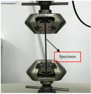
Tensile test is a mechanical test which is often used to identify the mechanical properties of the materials. The strength of the materials usually are the primary concern. For this test, five specimens according to ASTM D 3039 were cut
from each RTM and VIP specimens using the SHIMADZU testing machine as shown in Figure 1. The samples were left to break until the ultimate tensile strength occurs.
Fig. 1 Tensile test using SHIMADZU testing machine.
The tensile test was conducted by the SHIMADZU testing machine with crosshead speed testing of 2 mm/min and maximum load of 100 kN. The specimen will be holding in perpendicular to the applied load and placed in the grips of the test machine at a specific grip separation and pulled until failure.
B. Flexural Testing
Flexural test measures the force required to bend a beam under three point loading conditions. Flexural modulus is used as an indication of a material’s stiffness when flexed. In this test, all the sample prepared according to ASTM D 7264.
Fig. 2. Flexural test using INSTRON testing machine
Flexural test was conducted by INSTRON testing machine as shown in Figure 2, with crosshead speed testing of 2 mm/min and maximum load of 100 kN. The specimen was placed on two supported stage and a load was applied with a certain length of support span based on the thickness of each specimen type.
Supporting Pin
190605-2323-IJMME-IJENS © October 2019 IJENS I J E N S C. Morphological Analysis
The microstructure of the tested specimen was assessed using scanning electron microscopy (SEM) model as shown in Figure 3. The SEM machine was used for the morphological testing in order to analysed and study the damage specimen’s behaviour of carbon laminate composites. Other than that, this machine is also used to conduct and explore the nature bonding of the fiber and the matrix.
Fig. 3. Morphological test using SEM testing machine
III. RESULTS AND DISCUSSION
A. Effect of Tensile Strength and Flexural on Laminate Composites Fabricated by using RTM Process
Figure 4 to Figure 7 shows the results of the effect of tensile strength and flexural strength on laminated composite fabricated by using RTM process.
The graph shows in Figure 4 and Figure 5 are the results obtained based on the experiment conducted on the tensile strength by using the RTM process. Based on the graph in Figure 4, the highest value of ultimate tensile strength of carbon fiber laminate composite fabricated using RTM process is 386.30 MPa which is at VIP 16CF/EP, while the tensile strength is at its lowest strength to 140.97 MPa when the carbon fiber layer is at VIP 1CF/EP. For the graph shown in Figure 5, is the specific strength results and the condition of the composite fabricated using the RTM process on tensile test. Based on the results, it is shown that at RTM 8CF/EP, the composite is at its highest strength among other composites which is 16.32 MPa/g. The carbon fiber laminate fabricated hit its lowest strength to 3.62 MPa/g when the carbon layer is at VIP 32CF/EP.
Compare to the graph shown in Figure 6 and Figure 7 are the results obtained based on the experiment conducted on the flexural strength by using the RTM process. Based on the graph in Figure 6, the highest value of ultimate flexural strength of carbon fiber laminate composite fabricated using RTM process is 231.31 MPa which is at RTM 8CF/EP, while the flexural strength is at its lowest strength to 89.44 MPa when the carbon fiber layer is at RTM 1CF/EP. For the graph shown in Figure 7, is the specific strength results and the condition of the composite fabricated using the RTM process
on flexural test. Based on the results, it is shown that at RTM 1CF/EP, the composite is at its highest strength among other composites which is 65.50 MPa/g. The carbon fiber laminate fabricated hit its lowest strength to 5.07 MPa/g when the carbon layer is at RTM 32CF/EP.
Fig. 4. Ultimate tensile strength of carbon fiber laminate fabricated using the RTM process
Fig. 5. Specific strength of carbon fiber laminate fabricated using RTM process on flexural strength
190605-2323-IJMME-IJENS © October 2019 IJENS I J E N S
Fig. 7. Specific strength of carbon fiber laminate fabricated using RTM process on flexural strength
B. Effect of Tensile strength and Flexural on Laminated Composites Fabricated by using VIP Process
Figure 8 until Figure 11 shows the results of the effect of tensile strength and flexural strength on laminated composite fabricated by using VIP process.
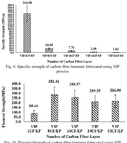
The graph shows in Figure 8 and Figure 9 are the results obtained based on the experiment conducted on the tensile strength by using the VIP process. Based on the graph in Figure 8, the highest value of ultimate tensile strength of carbon fiber laminate composite fabricated using VIP process is 252.18 MPa which is at VIP 1CF/EP, while the tensile strength is at its lowest strength to 74.26 MPa when the carbon fiber layer is at VIP 32CF/EP. For the graph shown in Figure 9, is the specific strength results and the condition of the composite fabricated using the VIP process on tensile test. Based on the results, it is shown that at VIP 1CF/EP, the composite is at its highest strength among other composites which is 164 MPa/g. The carbon fiber laminate fabricated hit its lowest strength to 1.62 MPa/g when the carbon layer is at VIP 32CF/EP.
Compare to the graph shown in Figure 10 and Figure 11 are the results obtained based on the experiment conducted on the flexural strength by using the VIP process. Based on the graph in Figure 10, the highest value of ultimate flexural strength of carbon fiber laminate composite fabricated using VIP process is 281.41 MPa which is at VIP 8CF/EP, while the flexural strength is at its lowest strength to 89.44 MPa when the carbon fiber layer is at VIP 1CF/EP. For the graph shown in Figure 11, is the specific strength results and the condition of the composite fabricated using the VIP process on flexural test. Based on the results, it is shown that at VIP 8CF/EP, the composite is at its highest strength among other composites which is 81.53 MPa/g. The carbon fiber laminate fabricated hit its lowest strength to 2.97 MPa/g when the carbon layer is at VIP 32CF/EP.
Fig. 8. Ultimate tensile strength of carbon fiber laminate fabricated using VIP process
Fig. 9. Specific strength of carbon fiber laminate fabricated using VIP process
Fig. 10. Flexural Strength of carbon fiber laminate fabricated using VIP process
190605-2323-IJMME-IJENS © October 2019 IJENS I J E N S C. SEM Analysis
The composite made of RTM technique reveals that the matrix and fibre are well-adhered as shown in Figure 12.
Fig. 12. SEM image on composite made of RTM technique on tensile test
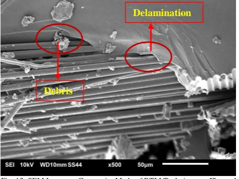
The image shows fewer voids and reduced pull-outs on the fractured surface. The smooth surface of the resin rich region found on the image indicated that the absence of crack propagation contributed to a better material. Figure 13 shows the image on composite made of RTM technique base on flexural test.
Fig. 13. SEM Image on Composite Made of RTM Technique on Flexural Test
From the SEM analysis in Figure 13, the left over debris found on the composite are due to the shearing between fibre and matrix during the failure of the composite. The fibres were delaminated from the matrix during the breakage of the composites
IV. CONCLUSIONS
The results obtained from this study have reported on the mechanical properties of the carbon fiber-reinforced composite by using two fabrication processes, which is the RTM process and VIP process. The results from tensile strength show that the higher number of carbon fiber layer in each composite did not give higher strength of the composite. It is found that the 16CF/EP composites fabricated by RTM are the highest tensile strength compared from both composites fabricated by RTM and VIP. While the flexural strength results show that the composites fabricated using VIP, which is VIP 8CF/EP composites has the highest flexural strength compared to composites fabricated using RTM. However, specific strength obtained from tensile test and flexural strength for composites both processes summarized that composites fabricated using VIP has the best results compared to RTM. Such observations are possibly due to the brittle nature of the matrix. Moreover, RTM has an excellent surface finish on both sides and this process is high repeatability in production cycles compared to the vacuum infusion process. However, based on mechanical properties obtained from this research, VIP produced the best specific strength on tensile and flexural tests.
ACKNOWLEDGMENT
This research has been conducted under the industrial matching grant scheme between PROTON and Universiti Teknikal Malaysia Melaka (UTeM) under project number Gluar/PROTON/2016/FKP-AMC/I00007. Special thanks to technical staffs and researchers from Faculty of Mechanical Engineering and Faculty of Mechanical and Manufacturing Engineering Technology, University Teknikal Malaysia Melaka (UTeM) for their assistance in conducting this research.
REFERENCES
[1] Mun, W.C., Rivai, A., and Bapokutty, O., 2014. Design and Analysis of an Aircraft Composite Hinge Bracket using Finite Element Approach. Applied Mechanics and Materials, 629, pp.158–163. [2] Kalanchiam, M. and Chinnasamy, M., 2012. Advantages of Composite
Materials in Aircraft Structures. International Journal of Mechanical,
Aerospace, Industrial, Mechatronic and Manufacturing Engineering, 6
(11), pp.2428–2432.
[3] Laurenzi, Susanna & Marchetti, M. (2012). Advanced Composite Materials by Resin Transfer Molding for Aerospace Applications, pp. 197-226.
[4] H. N. Dhakal, M. Skrifvars, K. Adekunle, and Z. Y. Zhang, “Falling weight impact response of jute/methacrylated soybean oil bio-composites under low velocity impact loading,” Composites Science
and Technology, vol. 92, pp. 134–141, 2014.
[5] Fadzullah, S.H.S.M., Mustafa, Z., Ramli, S.N.R., Yaacob, Q.., and Yusoff, A.F.., 2016. Preliminary Study on the Mechanical Properties of Continuous Long Pineapple Leaf Fibre Reinforced PLA Biocomposites.
Key Engineering Materials, 694 (i), pp.18–22.
[6] S. N. R. Ramli, S. Fadzullah, and Z. Mustafa, “Mechanical performance of pineapple leaf fiber reinforced poly lactic acid (PLA) biocomposites,” Proceedings of Mechanical Engineering Research
Day 2016, no. March, pp. 131–132, 2016.
[7] Prashanth Banakar and Shivananda, H.K., 2012. Preparation And Characterization Of The Carbon Fibre Reinforced Epoxy Resin Composites. Journal of Mechanical and Civil Engineering, 1 (2), pp.15–18.
Small gap between fibres Rich Resin Area
Delamination
190605-2323-IJMME-IJENS © October 2019 IJENS I J E N S
[8] Wambua, P., Ivens, J., and Verpoest, I., 2003. Natural fibres : Can They Replace Glass in Fibre Reinforced Plastics? Composites Science
and Technology, 63, pp.1259–1264.
[9] Kiran, B.V.B. and Harish, G., 2013. Effect of Resin and Thickness on Tensile Properties of Laminated Composites. American International Journal of Research in Science, Technology, Engineering &
Mathematics, 5 (2), pp.128–134.
[10] Reis, P.N.B., Ferreira, J.A.M., Antunes, F.V., and Costa, J.D.M., 2007. Flexural Behaviour Of Hybrid Laminated Composites. Composites - Part A: Applied Science and Manufacturing, 38, pp.1612–1620. [11] Sai, M.K.S., 2016. Review of Composite Materials and Applications.
International Journal of Latest Trends in Engineering and Technology,
6 (3), pp.129–135.
[12] Thori, P., Sharma, P., and Bhargava, M., 2013. An Approach Of Composite Materials In Industrial Machinery : Advantages, Disadvantages And Applications. International Journal of Research in
Engineering and Technology, pp.350–355.
[13] Richardson, M.O.W. and Zhang, Z.Y., 2000. Experimental Investigation And Flow Visualisation Of The Resin Transfer Mould Filling Process For Non-Woven Hemp Reinforced Phenolic Composites, 31, pp.1303–1310.
[14] Abdurohman, K., Satrio, T., Muzayadah, N.L., and Teten, 2018. A Comparison Process Between Hand Lay-Up , Vacuum Infusion And Vacuum Bagging Method Toward E-Glass EW 185 / Lycal Composites. In: 6th International Seminar of Aerospace Science and