VIRTUAL SWITCHING PANEL BY DETECTING
POSITION AND COLOR OF OBJECT
Arashdeep Kaur1
I. INTRODUCTION
Virtual switching panel is a virtual replica of an actual switching panel. The switching of main panel is controlled by using this virtual panel. A number of researchers have worked on human- machine interface and gesture recognition using various algorithms. A human interface by finger gesture on omni-directional image sensor has been proposed [1] which identifies the actions of push, pull, rotating and translating by variation of the finger parameters. It was concluded that a good evaluation for rotating and squeezing operation could be obtained. A technique has been introduced [2] which allows motion of hand in front of camera to manipulate a virtual object, and the gestural movements are recognized instantaneously to begin an interactive communication with computational systems. The interface was evaluated by questionnaire, and several problems were obtained. A novel human-machine interface using a “virtual switch”, has been represented [3] whereby a traditional switch is replaced with merely an image of a switch on a surface. The comparison between physical switch and virtual switch has also been provided. A framework based approach has been developed [4] to extract and recognize hand gestures from video sequence acquired by a dynamic camera, which could be useful interface between humans and mobile robots. A technique [5] has been introduced which allows user to change the position of his hand in front of a camera to manipulate a virtual object, and then there is recognition of gestural movements in real-time to set up an intermutual interaction with computational systems. A feature extraction method [6] has been developed for hand gesture based on multi-layer perceptron in which a hand gesture recognition method is proposed using combination of features and MLP. A method to recognize bare hand gestures using dynamic vision sensor (DVS) camera [7] has been provided. This paper describes a novel human-machine interface using a “virtual switch”, to avoid these mentioned problems of the actual switching panel. It is basically an interface for the user to give an input. MATLAB and
1
Department of electronics and communication engineering, IMSEC, Ghaziabad, India
e-ISSN:2278-621X
Abstract: An actual switching panel occupies a lot of space and along with that if a new device has to be added then it might lead to short circuit problems which can also be hazardous. Because of this, virtual switching panel has become attraction for many researchers. Virtual switching panel is a virtual replica of an actual switching panel. The switching of main panel is controlled by using this virtual panel. This paper describes a novel human-machine interface using a “virtual switch”, to avoid these mentioned problems of the actual switching panel. It is basically an interface for the user to give an input. MATLAB and embedded system are used for this device. Virtual switch uses lesser space and can be shifted to any desired location. Also the problem of short circuits is removed.
embedded system are used for this device. Virtual switch uses lesser space and can be shifted to any desired location. Also the problem of short circuits is removed.
II. METHODOLOGY
The whole project is divided in two main steps:
1. User end: This is basically an interface (the virtual panel) for the user to give an input to the system i.e. the selection of a switch. Image processing detects the selection. And the input is further received by the next stage that is the processing stage.
2. Processing: This processing stage takes the user input which is then processed and the necessary signal is provided to the switch which the user intends to operate. This stage uses embedded system for the processing.
III. HARDWARE SYSTEM REQUIREMENTS
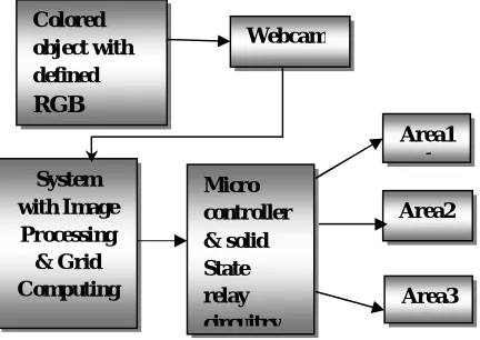
The main block diagram of the system is shown in Figure 1.There are four main parts of this project:
1) Input (By Switching Panel Using Image Processing in MATLAB), 2) PC Interfacing, 3) Microcontroller Circuitry 4) Solid State Relay Circuitry & Output
Firstly, the image in front of camera is captured. Then the shape and color of the object or gesture in the image is detected by using MATLAB which is installed in the computer. The RGB of the colored object is already defined in the system. According to the detected RGB of the object, the related device is switched on or off and the speed of the connected dc motor is also controlled using MATLAB commands. Other components include Microcontroller ATMEGA 16 board, home automation circuit, RS232 serial port, IR Transmitter-Receiver, Power Supply, dc motor and relays etc.
A.1 Input (By Switching Panel Using Image Processing)
MATLAB provides an efficient method for developing interfaces with users. Also it is convenient to use as it is user friendly.
A.1.1 Image Processing
Image processing is a mechanism used to transform an image into digital form. The image signal can be either digital or analog. The actual output itself can be a real physical image or the features of an image.
Fig 1: Block diagram of virtual switching pannel A.1.2 Digital Image
Colored object with defined RGB
Webcam
System with Image Processing & Grid Computing
Micro controller & solid State relay circuitry
Area1 1
Area2
A digital image is a represents a two-dimensional image as a finite set of digital values, called picture elements or pixels. Images are typically generated by illuminating a scene and absorbing the energy reflected by the objects in that scene.
Gray levels, colors, heights, opacities etc. are represented by pixel values Digital image processing focuses on two major tasks:
Pictographic data, for human interpretation is enhanced.
Processing of image data for storage, transmission and representation for autonomous machine perception.
A.2 PC Interfacing
Main parts in PC Interfacing are:
i) PC Serial Pin out Configuration
ii) MAX-232
A.2.1 Serial Connector
To allow congruity among data communication equipment made by various manufacturers, an interfacing standard called RS232 was set by Electronics Industries Association (EIA) in 1960.
Table 1 provides pins, their directions and their labels for RS232 cable, commonly referred to as DB-25 connector. To ensure fast and consistent data conveyance between two devices, the data transfer must be coordinated. Many pins of RS-232 connector are used for handshaking signals. Their description is provided below:
DTR (data terminal ready)
When terminal is turned on, it transmits signal DTR to imply that it is ready for communication.
DSR ( data set ready)
When DCE is turned on and has undergone the self-test, it asserts DSR to indicate that it is ready to communicate.
RTS ( request to send)
It activates the RTS to transfer the signal to modem and tells that it has a byte .
CTS ( clear to send )
When the modem has space to store the data it is to receive, it sends out signal CTS to DTE to indicate that it is ready to accept the data now.
DCD ( data carrier detect)
The modem asserts signal DCD to inform the DTE that a valid carrier has been identified and that contact between it and the other modem is established.
RI ( ring indicator)
An input to PC and output from the modem indicates that the telephone is ringing. It goes on and off in synchronous with the ringing sound.
A.2.2 MAX-232
+5V (roughly 0V ... +0.8V specified as low for binary '0', +2V ... +5V for high binary '1'. Modern low-power logic works in the range of 0V ... +3.3V or even lower.
The MAX-232 converts from RS232 voltage levels to TTL voltage levels, and vice versa. Table 2 shows the voltage levels of RS232 being converted to TTL voltage levels with help of MAX-232 and their logic levels. Figure 4shows that MAX-232 has two sets of line drivers for transfer and reception of data. The line drivers used for TxD are called T1 and T2, while drivers for RxD are labeled as R1 and R2. In many applications only one of each is used. Table 1 shows the pin layout of MAX-232.
Table 1.PIN OUT OF 9-PIN SERIAL CONNECTOR
DB-9 Name Direction Specification
1 CD Carrier Detect
2 RxD Receive Data
3 TxD Transmit Data
4 DTR Data Terminal
Ready
5 GND System Ground
6 DSR Data Set Ready
7 RTS Request to Send
8 CTS Clear to Send
9 RI Ring Indicator
Table 2.LOGIC FOR MAX-232
RS-232 TTL Logic
-15V… -3V +2V … +5V 1
+3V … +15V 0V … + 0.8V 0
3.2.3 MICROCONTROLLER CIRCUITRY
ATMEGA 16 is high-performance, low-power 8-bit Microcontroller with advanced RISC architecture. Various features of ATMEGA 16 are discussed below.
A.2.3.1 MICROCONTROLLER (ATMEGA 16)
Various features of ATMEGA 16 are as follows:
In Atmega16, we have 4 Ports named Port A, Port B, Port C and Port D.
Each port has 8 pins represented as: Port A- PortA.0 to Port A.7
Port B- PortB.0 to Port B.7 Port C- PortC.0 to Port C.7 Port D- PortD.0 to Port D.7
These ports and their pins can be used for taking input and giving output. Port A has in built ADC. So we can interface analog sensor directly with Port A. Port B, C and D are Digital Ports.
Port A (PA7 – PA0) – 8 I/O pins. This port also act as Analog to Digital Converter
Port C (PC7 – PC0) – 8 I/O pins.
Port D (PD7 – PD0) – 8 I/O pins.
Any single pin or entire port can be configured as input or output
RESET – Low at this pin resets the counter and restarts the execution of the program
Vcc – Power supply to the microcontroller
AVcc – Separate power supply to the A/D converter
Aref – Reference to the Analog Signals at ADC
So in total, we can interface maximum of 8 analog sensors to ATMEGA 16 Microcontroller at one
A.2.3.3BASCOM-AVR SOFTWARE
BASCOM – AVR is an IDE based development platform and is developed by MCS Electronics. BASCOM utilizes BASIC programming language. It is very simple to write, compile and download the program with BASCOM.
A.2.4Solid State Relay Circuitry and Output
A +12V and +5V DC supply is needed for our circuit for this we use regulated power supply. An ideal regulated power supply is an electronic circuit designed to provide a predetermined DC voltage which is not dependent on the current drawn, temperature and any discrepancy in line.
This circuit comprises of a transformer, a bridge rectifier, a ∏ filter and also contains a
regulator IC 7812. Also for testing purpose a 5 volt DC, regulated power supply is also made by using regulator IC 7805.
For getting the DC supply, first with the help of transformer we convert high voltage AC to low voltage AC supply, then by a rectifier circuit, the AC supply is converted into pulsating DC supply. For the control of spikes a capacitor is connected in parallel. For filtering the DC
component, a п filter is used. Regulator IC is used to produce a regulated 12V DC supply. A capacitor between its input terminal and common terminal is used for protection against blackout and a capacitor between its output terminal and common terminal is used for spike control.
IV. DC MOTOR
By motor an electrical energy is converted into mechanical energy. It utilizes a DC supply to generate the mechanical output. Generally they are used over conventional AC motors due to:-
(i) The controller efficiency is high.
(ii) The efficiency of DC motor is typically around 98%. (iii)They have better peak voltage and overload characteristics.
(iv) In this speed- torque characteristics can be changed to any useful form.
These motors can be used in many applications where at varying loads a constant speed has to be maintained. The DC motors are applied in applications such as Conveyor belts, cranes, ski lifts, mixers, sewing machines and many more. So it is required to control the speed of DC motor and required place to work on.
V. CODING
used to get the different pixel values of the digital image and with the help of these values, the switching of various devices has been controlled.
VI. EXPERIMENTAL RESULTS
Based on the project work carried out on virtual switching panel which involved study and comparison between physical switch and virtual switch, the various data were collected and a prototype of virtual switching system was made. The trends and inferences taken out from the study and implementation of virtual switching panel and summary of result have been explained.
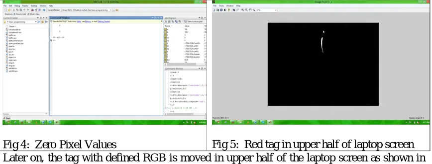
Figure 2 shows a snapshot of image which consists of a tulip flower having a red tag whose RGB is already defined in the MATLAB which is installed in the system. Different values of pixels for this red tag give different outputs. The output will be either switching on of device or switching off of the device which is bulb in this case, connected to the port of ATMEGA16.
Fig 2: Image with red tag Fig 3: No Action
Firstly no action is assumed which is shown in Figure 3. The webcam, in built, in the laptop does not detect any red tag in the image captured by it. Figure 4 is the command window showing zero values for pixels. This indicates that no action will be taken following zero pixel values which indicates the absence of desired tag.
Fig 6: Pixel values for upper half screen of
laptop Fig 7: Red tag in lower half of laptop screen
Fig 8: Pixel values for lower half of the screen
Now the red tag is moved to the lower half of the laptop screen as shown in Fiure 7. The command window in Figure 8 gives the pixel values 525.1816 and 581.4574 which are x and y coordinates of the laptop screen. These coordinate values correspond to the lower half of the screen which gives command to the connected device to switch off.
In this way, it is concluded that for different pixel values of the red tag with defined RGB, different outputs are obtained. So various devices conneceted to the microcontroller can be switched on or off depending on whether the red tag is in upper half or lower half of the screen of laptop used.
VII. CONCLUSION
In this paper we have presented a framework for detection of the position and color of the object or image, which is detected by using MATLAB installed in the computer. The required MATLAB coding has been done for the required result. It is expected that the use of virtual switching panel will enhance the performance of the field in which it is used as it gets rid of the wiring which is there in normal switches which leads to a lower maintenance, use of lesser area and no short circuiting.
REFERENCES
[1]. MontonoroiDoi, Shinji Ueda, Kohei Akiyama, “Human Interface based on Finger Gesture Recognition using Omni-Directional Image Sensor”, VECIMS 2003 – International Symposium on Virtual Environments, Human-Computer Interfaces, and Measurement Systems Lugano, Switzerland, pp68-72, July, 2003.
[3]. Ulka S. Rokade, DharmpalDoye, ManeshKokare, “Hand Gesture Recognition UsingObject Based Key Frame Selection”, International Conference on Digital Image Processing, IEEE, pp288-292, May, 2009. [4]. Radu-Daniel Vatavu, Ovidiu-CiprianUngurean, Stefan Gheorghe Pentiue, “Facilitating Selection and
Travel Tasks in Virtual Environments using a Motion Sensitive Hand-Held Device”, Intelligent Computer Communication and Processing, ICCP 2009, IEEE 5th International Conference on IEEE, pp329-334, August, 2009.
[5]. Hirofumi Takase, Hideyuki Sawada, “Gestural Interface and the Intuitive Interaction with Virtual Objects”, ICROS-SICE International Joint Conference 2009, Fukuda International Congress Center, Japan, pp3260-3263, August, 2009.
[6]. Chenglong Yu, Xuanwang, Hejiao Huang, Jianping Shen, Kun Wu, “Vision-Based Hand Gesture Recognition Using Combinational Features”, 2010 Sixth International Conference on Intelligent Information Hiding and Multimedia Signal Processing, pp543-545, August, 2010.
[7]. EunYeongAhn, Jun Haeng Lee, Tracy Mullen, John Yen, “Dynamic Vision SensorCamera Based Bare Hand Gesture Recognition”,Computational Intelligence for Multimedia, Signal and Vision Processing (CIMSIVP), 2011 IEEE Symposium on IEEE, pp342-348, July, 2011.
[8]. Sharma, N. and Sharma, H. HIM: Hand Gesture Recognition in Mobile-learning. Int. J. of Comp. Applications, 44(16) (April 2012), 33 – 37 ,New York ,USA.
[9]. Singh, S., Jain, A. and Kumar, D. Recognizing and Interpreting Sign Language Gesture for Human Robot Interaction. Int. J. of Computer Applications, 52 (11) (August 2012) 24 - 30 USA.
[10]. Stephen Mascaro, H. Harry Asada, “Virtual Switch Human Interface using FingernailTouch Sensors”, Proceedings of the 1999 IEEE International Conference on Robotics & Automation Detroit, Michigan, pp2533-2588, May, 1999.
[11]. M.K. Bhuyan, D. Ghoah, P.K. Bora, “A Framework for Hand Gesture Recognition with Applications to Sign Language”, India Conference, 2006 Annual IEEE, pp234-240, May, 2006.
[12]. Xu Zhang, Xiang Chen, Yun Li, Vuokko Lantz, Kongqiao Wang, Jihai Yang,” AFramework for Hand Gesture Recognition Based on Accelerometer and EMG Sensors”, IEEE Transactions on Systems, Man, And Cybernetics—Part A: Systems And Humans, Vol.41, No.6, pp89-92, November, 2011.
[13]. Jonathon Alon, VassilisAthitsos, Quan Yuan, Stan Sclaroff, “Simultaneous Localization and Recognition of Dynamic hand Gestures”, Proceedings of the IEEE Workshop on Motion and Video Computing, IEEE, pp45-52, August, 2005.
[14]. Gerd Bruder, Frank Steinicke, Phil Wieland, “Tuning Self-Motion Perception in Virtual Reality with Visual Illusions”, IEEE Transactions on Visualization And Computer Graphics, Vol.18, No.7, pp75-82, July, 2012.
[15]. Yui Man Lui, “A Least Squares Regression Framework on Manifolds and its Application to Gesture Recognition”, 2012 IEEE Computer Society Conference on Computer Vision and Pattern Recognition Workshops (CVPRW), , pp13-18, February, 2012.
[16]. Dan Luo, Jun Ohya, “Study on Human Gesture Recognition From Moving Camera Images”, ICME, 2010 IEEE International Conference on Multimedia and Expo, pp274-279, May, 2010.
[17]. Hae Jong Seo, PeymanMilanfar “A Review on Action Recognition from One Example”, IEEE Transactions on Pattern Analysis And Machine Intelligence, vol. 33(5), may 2011,USA.
[18]. Denis Amelynck, Maarten Grachten, Leon Van Noorden, and Marc Leman. “Toward E-Motion-Based Music Retrieval a Study of Affective Gesture Recognition”, IEEE transactions on affective computing, vol. 3, no. 2, april-june 2012,USA.
[19]. Game P. M., Mahajan A.R,” A gestural user interface to Interact with computer system”, International Journal on Science and Technology (IJSAT) Volume II, Issue I, (Jan.-Mar.) 2011, pp.018-027 ,India. [20]. Bhuyan, M. K., Neog, D. R. and Kar, M. K. Fingertip Detection for Hand Pose Recognition. Int. J. On