(UDC: 004.922:519.673]:624.073.41)
Geometrically nonlinear analysis of laminated composite plates using a
layerwise displacement model
M. Ćetković1*, Dj. Vuksanović2
1Faculty of Civil Engineering, University of Belgrade, Bul. Kralja Aleksandra 73, 11000
Belgrade, Serbia
2Faculty of Civil Engineering, University of Belgrade, Bul. Kralja Aleksandra 73, 11000
Belgrade, Serbia [email protected]
Abstract
In this paper the geometrically nonlinear laminated finite element model is developed using the principle of virtual displacements (PVD). The 3D elasticity equations are reduced to 2D problem using kinematical assumptions based on assumed layerwise displacement field of Reddy. With the assumed displacement field, nonlinear Green-Lagrange small strain large displacements relations and linear orthotropic material properties for each lamina, the PVD is used to obtain the weak form of the problem. The weak form or nonlinear integral equilibrium equations are discretized using isoparametric finite element approximation. The nonlinear incremental algebric equilibrium equations are solved using the direct iteration procedure. The original MATLAB computer program is coded for finite element solution and is used to investigate the geometrical nonlinear effects on displacement and stress field of thin and thick, isotropic, orthotropic and anisotropic laminated composite plates with various boundary conditions and the sign of the loading (loading/unloading). The accuracy of the numerical model is verified by comparison with results from the literature and the linear solutions from the previous paper. Appropriate conclusions are derived.
Key words: geometrically nonlinear analysis, layerwise finite element model
1. Introduction
The above mentioned features resulted in large weight savings and made possible the use of very thin composite plate elements. However these elements become susceptible to large deflections during their service life (Polat et al. 2007, Zhang et al. 2006). In such cases the geometry of structure is continually changing during the deformation and geometrically nonlinear analysis should be adopted. The geometrically nonlinear analysis seems also to be necessary for obtaining the structural response of unsymmetrical laminated composite materials (Zhang et al. 2003). Namely, the nonlinear response of these laminates is present even for small displacements, due to complex coupling between in-plane and out-of plane deformation.
A considerable amount of research work has been carried out so far on the nonlinear analysis of laminated plates. Among the published works, the von Karman plate theory of plates undergoing large deflections has attracted outstanding attention and a number of papers have been published. The first authors investigating the nonlinear response using the von Karman nonlinear theory (Tanriover et al. 2004, Reddy et al. 1983) were: Leissa, Bennett, Bert, Chandra and Raju, Zaghloul and Kennedy, Chia and Prabhakara, Noor and Hartley, and in the last decades Han, Tabiei and Park, Singh, Lal and Kumar, Reddy and Chao, Zhang Kim and others.
Mechanical response of laminated composite material is generally 3D problem of nonlinear mechanics. However, due to its mathematical complexity, analytical solutions using 3D theory of elasticity are usually difficult and some times even impossible to achieve, while numerical solutions are computationally inefficient and constrained to very specific domains. Thus, whenever possible, refined simplified mathematical models, with acceptable accuracy in a field of applications, should be used. It is shown that the Equivalent Single Layer theories (ESL) may give acceptable results when analyzing global response, such as gross deflections and gross stresses, critical buckling loads and fundamental frequencies of thin to moderate thick laminated composite plates (Vuksanovic 2000). However, a continuous displacement function in ESL is not able to accurately present the discontinuous zigzag variation of displacements in highly anisotropic plates and give adequate stress distribution at local or ply level (Cetkovic et al. 2009). A compromise between 3D theory of elasticity and ESL theories is then achieved with the use of Layer Wise theories (LW). In LW theories the in-plane displacement field, assumed for each layer, is interpolated through the thickness by appropriate layerwise Lagrange interpolation function or Heaviside step function (Reddy 2004), thus replacing 3D laminated element with N+1 2D plate elements (N is number of layers), which fulfills the continuity of displacement functions at the interfaces between adjacent layers.
From the continuum mechanics it is known that two different level of geometrical nonlinearity may be modeled, which are: geometrically nonlinear models with small strain and large displacements (von Karman theory) and geometrically nonlinear models with large strains. In the first case, the geometry of the structure before deformation remains unchanged after the deformation. However, the structure is subjected to large displacements and the equilibrium is achieved on the configuration displaced from the undeformed one. In the second case the geometry of the structure is changing during the deformation and the equilibrium is achieved on the deformed configuration. In both cases equilibrium equations are nonlinear.
both types on nonlinearity may be included. Finite elements based on this approach are called the continuum elements.
The aim of the author’s research on composite materials so far was to implement Layerwise theory of Reddy or Generalized Layerwise Plate Theory-GLPT (Reddy et al. 1989) on different levels of analysis of laminated composite plates. The previous work has been concerned with the linear analysis (Cetkovic et al. 2009), and the linear laminated plate element of GLPT has been formulated, while in the present paper the GLPT nonlinear laminated plate element with von Karman geometrical nonlinearity is presented.
In this paper the mathematical and numerical model for geometrically nonlinear, small strain, large displacements problem of laminated composite plates is presented. The 3D elasticity equations are reduced to 2D problem using kinematical assumptions based on layerwise displacement field of Reddy (GLPT). With the assumed displacement field, nonlinear Green-Lagrange small strain large displacements relations and linear orthotropic material properties for each lamina, the principle of virtual displacement (PVD) is used to derive the weak form of the problem. The weak form or nonlinear integral equilibrium equations are discretized using isoparametric finite element approximation. The obtained nonlinear incremental algebric equilibrium equations are solved using direct iteration procedure. The originally coded MATLAB computer program for the finite element solution is used to investigate the effects of geometrical nonlinearity on displacement and stress field of thin and thick, isotropic, orthotropic and anisotropic laminated composite plates with various boundary conditions and the sign of the loading (loading/unloading). The accuracy of the numerical model is verified by being compared with available results from the literature and the linear solutions from the previous paper (Cetkovic et al. 2009). The appropriate conclusions are derived.
2. Theoretical formulation
2.1 Displacement field
In the LW theory of Reddy (Reddy et al. 1989) or Generalized Layerwise Plate Theory (GLPT), in-plane displacements components
u,v are interpolated through the thickness using 1D linear Lagrangian interpolation function I
z , while transverse displacement component w is assumed to be constant through the plate thickness.
) y , x ( w ) z , y , x ( u
z y , x V ) y , x ( v ) z , y , x ( u
z y , x U ) y , x ( u ) z , y , x ( u
3
1 N
1 I
I I
2
1 N
1 I
I I
1
(1) thus giving the “zig-zag” or layer wise variation of the in-plane displacements. This “zig-zag”
2.2 Strain-displacement relations
The Green Lagrange strain tensor associated with the displacement field Eq.(1) can be computed using von Karman strain-displacement relation to include geometric nonlinearities as follows: 2 1 N 1 I I I 2 3 1 xx x w 2 1 x U x u x u 2 1 x u
2 1 N 1 I I I 2 3 2 yy y w 2 1 y V y v y u 2 1 y u
N 1
1 I I I I 3 3 2 1 xy y w x w x V y U x v y u y u x u x u y u (2) x w dz d U x u z
u N 1 I
1 I I 3 1 xz
y w dz d V y u zu N 1 I
1 I I 3 2 yz
2.3 Constitutive equations
For Hook’s elastic material, the stress-strain relations for k-th orthotropic lamina have the following form:
k
yz xz xy yy xx k 55 45 45 44 33 23 13 23 22 12 13 12 11 k yz xz xy yy xx Q Q 0 0 0 Q Q 0 0 0 0 0 Q Q Q 0 0 Q Q Q 0 0 Q Q Q (3) whereσ k
xx yy xy xz yz
k Tand
T k yz xz xy yy xx
k
ε
are stress and strain components respectively, and k ij
Q are transformed elastic coefficients, of k-th lamina in global coordinates.
2.4 Equilibrium equations
Equilibrium equations may be obtained from the Principle of Virtual Displacements (PVD), in which sum of external virtual work done on the body and internal virtual work stored in the body should be equal zero:
Q P
ds δU N ds δU N dswhere
0z
0 y 0 x,q ,qq is distributed load in x,y,z directions, while internal forces are:
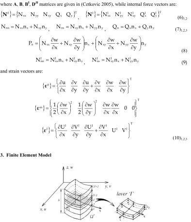
I m 0 I 0 ε ε ε D B B A N N N 1 J JI I I (5)where A, B, BI, DJI matrices are given in (Cetkovic 2005), while internal force vectors are:
Ty x xy yy xx
0 N N N Q Q
N ,
I
Ty I x I xy I yy I xx
I N N N Q Q
N (6)
1,2
y xy x xx
nn N n N n
N , Nns NxynxNyyny, Qn Qxnx Qyny (7)
1,2,3 y yy xy x xy xx n n y w N x w N n y w N x w N P (8) y I xy x I xx I
nn N n N n
N , NIns NIxynxNyyI ny (9)
and strain vectors are:
0 Ty w x w x v y u y v x u ε
T 2 2m 0 0
x w x w y w 2 1 x w 2 1 ε
I I I I I UI VI Tx V y U y V x U ε (10)1,2,3
3. Finite Element Model
Fig. 1. Plate finite element with n layers and m nodes.
each node only displacement components are adopted, that are
u,v,w
in the middle surface element nodes and
UI,VI
in the I-th plane element nodes. The generalized displacements over element e can be expressed as:
m 1 j e j e j e m 1 j j j m 1 j j j m 1 j j j e w v u w v u d Ψ
m 1 j e I j e j e m 1 j j I j m 1 j j I j e I I V U V U d Ψ (11)where
I
Tj I j e I j T e j e j e j e
j u v w , d U V
d are displacement vectors, in the
middle plane and I-th plane, respectively, e j
are interpolation functions, while
e jΨ ,
Ψj eare interpolation function matrix for the j-th node of the elemente, given in(Cetkovic et al. 2009). Substituting element displacement field Eq.(6) in to weak form Eq.(4), the nonlinear laminated finite element is obtained (Cetkovic et al. 2011):
e
e eNL d f
K (12)
where secant stiffness matrix is:
e 22 e 2 e 2 e e NL K K K K K 1 1 11
T
NL NL NL NL
1 1
2 2
e
m n
e e e e e e e e e e
i j i j i j i j
i j
d
K11
H T A H H T A H H T A H H A H
m 1 i n 1 j e e j T NL e i e j T e i e 2 e d2 H B H
H B H
K1 I I
m 1 i n 1 j e NL e j T e i e j T e i e e d H B H H B HK21 I I
(13)1,2,3,4
m 1 i n 1 j e e j e i e 2 e d H D HK2 T IJ
and external force vector
m 1 i e e n n ns nn T e i e e 0 z 0 y 0 x T e i e 0 d P Q N N dΩ q q q Ψ Ψ f
m 1 i e I ns I nn T e i e I y I x T e i e I d N N dΩ q q e e Ψ Ψ f (14)1,2 while:
y 0 0 x 0 0 0 x y 0 y 0 0 0 x e j e j e j e j e j e j e j e jH ,
0 0 0 0 0
0 y x
w y x w 0 0 y y w 0 0 x x w 0 0 2 1 e j e j e j e j NL e j
H ,
1 0 01y x
y 0 0 x e j e j e j e j e j e j
H (15)1,2,3
With the known displacement field, the stress field over the element may be obtained as a part of a postprocessor, using strain displacement and constitutive relations, Eqs. (2), (3) as:
m 1 j e I j k m 1 j e j NL j j k е к Ub Q H H d Q H j d
σ b b b b b
m 1 j e 1 I j k m 1 j e j NL j j k е к Ob Q H H d Q H j d
σ b b b b b
m 1 j k e I j e 1 I j j k m 1 j e j j k e k consts Q H d Q H d d /h
where
σb Uк е and
е к O bσ are in-plane normal stresses
xx,yy,xy
at bottom and upperplane in k-th layer of plate element ‘e’, while
σs constk e are average transverse shear stresses
xz,yz
in k-the layer of plate element.4. Numerical results and discussion
Based on the previously derived laminated finite element model for the geometrically nonlinear analysis of laminated composite plates, the original computer program is coded using MATLAB programming language. The quadratic Lagrange rectangular element with nine nodes and associated polynomial was used for isoparametric FE approximation of in-plane displacement of plate element and geometry. The nonlinear finite element secant stiffness matrix is evaluated using Gauss–Legendre quadrature rule, which are 3x3 Gauss integration schemes or 2D quadratic Lagrange rectangular element for in-plane interpolation and 1D linear Lagrange element for through the thickness interpolation. The direct iteration procedure, also known as the Picard iteration method was used as numerical procedure to solve nonlinear algebric equations, iterative in nature. The effects of plate thickness, lamination scheme, boundary conditions and the sign of the loading on nonlinear response of isotropic, orthotropic and anisotropic plates are analyzed. The accuracy of the present formulation is demonstrated through a number of examples and by comparison with results available from the literature.
The following boundary conditions at the plate edges are analyzed (Thankam et al. 2003). Simply supported (SS):
SS: yx 0,0,a:b: vu ww VU NN NNI 00 I 1, N 1 yy
yy I 0 0
I xx xx I 0
0
(17)
Simply supported-hinged (HH):
HH: xy 0,0,a:b: uu vv ww VU NNI 00 I 1, N 1
yy I 0 0 0
I xx I 0 0
0
(18)
Clamped (CC):
CC: xy 0,0,a:b: uu0 vv0 ww0 UUI VVI 00 I 1, N 1 I
I 0 0
0
(19)
When analyzing a quarter of a plate, boundary conditions in the plane of symmetry become: For cross ply laminates:
SS1: xy ab//22:: uv UV NN NNI 00 I 1, N 1
xx xx I 0
Iyy yy I
0
(20)
For angle ply laminates:
SS2: xy ab//22:: vu0 UVI NNyy NNIxx 00 I 1, N 1 I
yy xx I
0
Example 4.1. A nonlinear bending of square, simply supported (SS1), isotropic plate, with cm
4 . 25 b
a and h2.54cm made of material:
3 . 0 , 2 ^ cm / N 37791 , 5
E (22)
subjected to uniform transverse pressure is analyzed. Using the load parameter
4 40 a /Eh
q
P , the incremental load vector is chosen to be:
P
6.25,6.25,12.5,25.0,25.0,25.0,25.0,25.0,25.0,25.0
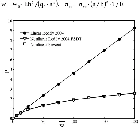
P (23)with convergence tolerance 0.01 and acceleration parameter 0,8. The displacements and stresses are given in following nondimensional form:
q a
,
a/h
1/E /Eh w
w 2
xx xx 4 0 3
0
(24)
0 50 100 150 200 0
1 2 3 4 5 6 7 8 9 10
w
P
Linear Reddy 2004 Nonlinear Reddy 2004 FSDT Nonlinear Present
Fig. 2. Nonlinear bending of square simply supported (SS1) isotropic plate with a/h10; central displacement versus load parameter.
Example 4.2. A nonlinear bending of square simply supported (SS1), orthotropic plate made of high modulus glass-epoxy fiber reinforced material:
, 2 . 0 E / G , 5 . 0 E / G , 5 . 0 E / G , 25 E /
E1 2 12 2 13 2 23 2
25 . 0
23 13
12
(25) subjected to uniform transverse pressure is analyzed. Using the load
parameter
4
2 4 0 a /E h
q
P , the incremental load vector is chosen to be:
P
10,20,30,40,50,60,70,80,90,100,110,120,130,140
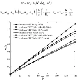
P (26)with convergence tolerance 0.01 and acceleration parameter 0,3. The displacements and stresses are given in following nondimensional form:
4
0 3 2
0 E h /q a
w
w
2 xz xz 2 2 xy yy xx xy yy
xx E
1 a h ,
E 1 a h ,
, ,
,
(27)1,2
0 20 40 60 80 100 120 140 0
0.2 0.4 0.6 0.8 1 1.2 1.4
w/h
P
linear (a\h=10 Reddy 2004) nonlinear FSDT (a\h=10 Reddy 2004) nonlinear GLPT (a\h=10 Present) linear (a\h=100 Reddy 2004) nonlinear FSDT (a\h=100 Reddy 2004) nonlinear GLPT (a\h=100 Present)
Fig. 3. Nonlinear bending of square simply supported (SS1) orthotropic plate; central displacement versus load parameter.
Example 4.3. A nonlinear bending of square cross ply 0/90 and angle ply 45/-45 plates, with
1 b
a and h0.1, with three different boundary conditions (SS, SS1 HH and CC, Eqs. 17, 18, 19, 20) , made of material:
25 . 0 ,
5 . 0 E / G , 6 . 0 E / G , 6 . 0 E / G , 40 E /
E1 2 12 2 13 2 23 2 12 13 23 (28)
subjected to uniform transverse pressure
2 4
E 1 h a y , x q
q
are analyzed. The incremental
load vector is:
q
100,20,20,20,20,40,20,20,20,20
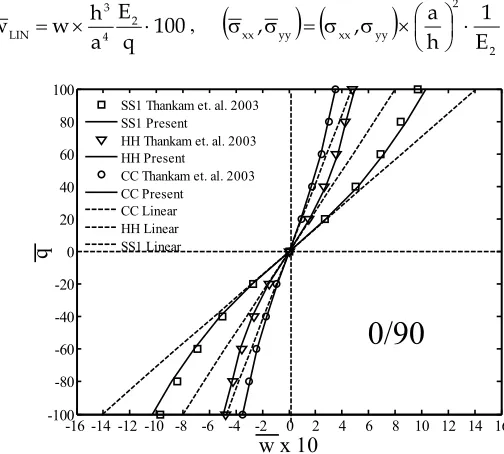
(29)with convergence tolerance 0.01 and acceleration parameter 0,5. The displacements and stresses are given in following nondimensional form:
100 q E a h w
w 2
4 3
LIN ,
2 2 yy
xx yy
xx E
1 h a ,
,
(30)
-16 -14 -12 -10 -8 -6 -4 -2 0 2 4 6 8 10 12 14 16 -100
-80 -60 -40 -20 0 20 40 60 80 100
w x 10
q
SS1 Thankam et. al. 2003 SS1 Present
HH Thankam et. al. 2003 HH Present
CC Thankam et. al. 2003 CC Present
CC Linear HH Linear SS1 Linear
0/90
Fig. 4. Nonlinear bending of square cross ply 0/90 plate with different boundary conditions and 10
h /
-10 -8 -6 -4 -2 0 2 4 6 8 10 -100
-80 -60 -40 -20 0 20 40 60 80 100
w x 10
q
SS (Thankam et al. 2003) SS (GLPT)
HH (Thankam et al. 2003) HH (GLPT)
CC (Thankam et al. 2003) CC (GLPT nonlinear) CC (linear) HH (linear) SS (linear)
45/-45
Fig. 5. Nonlinear bending of square angle ply 45/-45 plate with different boundary conditions and a/h10; central displacement versus load parameter.
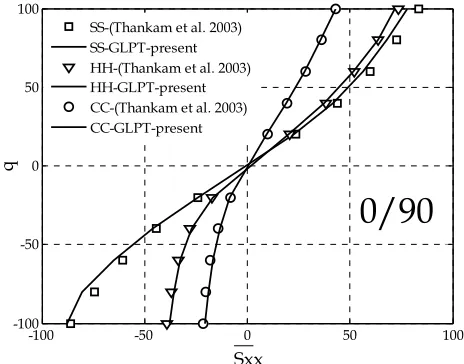
-100 -50 0 50 100
-100 -50 0 50 100
Sxx
q
SS-(Thankam et al. 2003) SS-GLPT-present HH-(Thankam et al. 2003) HH-GLPT-present CC-(Thankam et al. 2003) CC-GLPT-present
0/90
Fig. 6. Nonlinear bending of square cross ply 0/90 plate with different boundary conditions and 10
h /
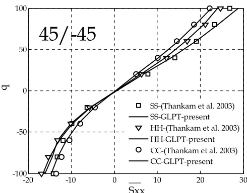
-20 -10 0 10 20 30 -100
-50 0 50 100
Sxx
q
SS-(Thankam et al. 2003) SS-GLPT-present HH-(Thankam et al. 2003) HH-GLPT-present CC-(Thankam et al. 2003) CC-GLPT-present
45/-45
Fig. 7. Nonlinear bending of square angle ply 45/-45 plate with different boundary conditions and a/h10; in plane stress Sxx versus load parameter.
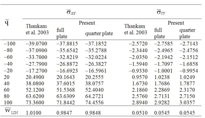
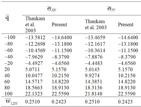
Table 1. Stresses versus load parameter of square simply-supported (SS, SS1) orthotropic plate 10
h /
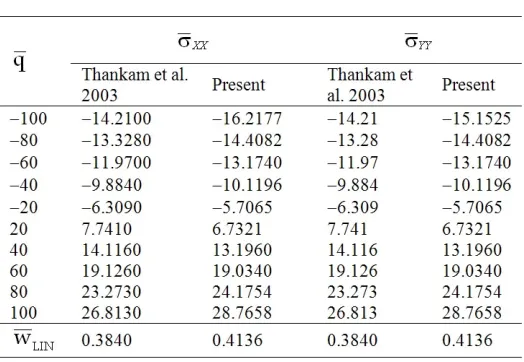
Table 2. Central displacement and stresses versus load parameter of square hinged (HH) cross ply 0/90 plate with a/h10.
Table 4. Central displacement and stresses versus load parameter of square simply-supported (SS) angle ply 45/-45 plate witha/h10.
Table 6. Central displacement and stresses versus load parameter of square clamped (CC) angle ply 45/-45 plate with a/h10.
A 2x2 quarter plate and 4x4 full plate laminated GLPT models are analyzed and compared with full 8x8 plate FSDT models (Thankam et al. 2003). The results for linear and nonlinear deflections and in plane stresses are presented in Figs. 4,5,6,7 and tables 1-6. It is shown that proposed GLPT model closely agree with FSDT model form literature. Also, the discrepancy between linear and nonlinear solutions are larger for flexible plates, which are the plates with simply supported boundary conditions (SS, SS1), compared to hinged (HH) and clamped (CC) boundary conditions. The study has verified that the change in the sign of the load gives unsymmetrical stress field and symmetrical displacement field, due to non-coincidence of the neutral plane and the mid-plane in laminated composite plates.
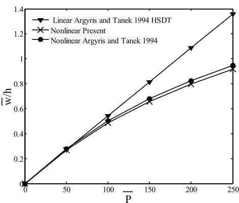
Example 4.4. A nonlinear bending of square simply supported (SS1) general quasi-isotropic (0/45/-45/90)s, laminated plate with ab1 and h0.1, made of material:
25 . 0 ,
5 . 0 E / G , 6 . 0 E / G , 6 . 0 E / G , 40 E /
E1 2 12 2 13 2 23 2 12 13 23 (31)
subjected to uniform transverse pressure is analyzed. Using the load parameter
4
2 4 0 a /E h
q
P , the incremental load vector is chosen to be:
q
50,50,50,50,50
P (32)0 50 100 150 200 250 0
0.2 0.4 0.6 0.8 1 1.2 1.4
P
w/h
Linear Argyris and Tanek 1994 HSDT Nonlinear Present
Nonlinear Argyris and Tanek 1994
Fig. 8. Nonlinear bending of square simply supported (SS1) general quasi-isotropic (0/45/-45/90)s laminated plate with a/h10; central displacement versus load parameter
A 2x2 quarter plate continuum GLPT model is compared with 8x8 full plate HSDT model (Argyris and Tanek 1994). The results for linear and nonlinear deflections are presented in Fig. 8. It is shown that proposed GLPT model closely agree with HSDT model form literature, with the faster convergence.
5. Conclusion
Геметријски нелинеарна анализа ламинираних композитних плоца
корисцењем слојевитог модела померања
M. Ćetković1*, Dj. Vuksanović2
1Faculty of Civil Engineering, University of Belgrade, Bul. Kralja Aleksandra 73, 11000
Belgrade, Serbia [email protected]
2Faculty of Civil Engineering, University of Belgrade, Bul. Kralja Aleksandra 73, 11000
Belgrade, Serbia [email protected]
Уовомрадујеразвијенгеометријскинелинеаранламиниранимоделконачнихелемената
коришћењемпринципа виртуалнихпомерања. 3Дједначине еластичностисусведене на
2Д проблем коришћењем кинематских претпоставки базираних на претпостављеном
пољу померања слојева Редија. Са претпостављеним пољем померања, нелинеарним
Грин – Лагранжевимрелацијама замаледеформације ивелика померања, и линеарним
ортотропнимматеријалнимкарактеристикамазасвакислој (плочу), принципвиртуалних
померања је коришћен за добијање слабе форме. Слаба форма или нелинеарне
интегралне равнотежне једначине дискретизовани су коришћењем изопараметарских
апроксимацијауконачнимелементима. Нелинеарнеинкременталнеалгебарскеједначине
сурешаванепоступкомдиректнихитеграција. НаписанјеоригиналниМАТЛАБпрограм
за решавање методом коначних елемената, који је коришћен је за истраживање
геометријски нелинеарних ефеката на поља померања и напона код танкиии дебелих,
изотропних, ортотропних и анизотропних слојевитих композитних плоча са
променљивим граничним условима и знаком оптерећења (оптерећење - растерећење).
Тачност нумеричког модела је верификована упоређивањем са резултатима из
литературе и линеарним решењима из претходног рада. Изведени су одговарајући
закључци.
Кључне речи: геометријскинелинеарнаанализа, слојевитимоделконачнихелемента
References
Argyris, J. and Tanek, L. (1994), “Linear and geometrically nonlinear bending of isotropic and multilayered composite plates by the natural mode method”, Computer methods in applied mechanics and engineering, 113, 207-251.
Ćetković M, Vuksanović Dj (2009), “Bending, Free Vibrations and Buckling of Laminated Composite and Sandwich Plates Using a Layerwise Displacement Model, Composite Structures, 88(2) pp. 219-227
Ćetković, M. (2005), Application of finite element method on generalized laminated plate theory, Master Thesis, in serbian, Faculty of Civil Engineering in Belgrade, Serbia.
Ćetković, M. (2011), Nonlinear behaviour of laminated composite plates, PhD Thesis, in serbian, Faculty of Civil Engineering in Belgrade, Serbia.
Reddy JN, Barbero EJ, Teply JL. (1989), A plate bending element based on a generalized laminated plate theory, International Journal for Numerical Methods in Engineering, 28, pp. 2275-2292
Reddy, J.N. (2004), Mechanics of laminated composite plates-theory and analysis, CRC press. Reddy, J.N. and Chao, W.C. (1983), “Nonlinear bending of bimodular-material plates”,
International Journal of Solids and Structures, 19(3), pp. 229-237.
Tanriover, H. and Senocak, E. (2004), “Large deflection analysis of unsymmetrically laminated composite plates: analytical-numerical type approach”, International Journal of Non-linear Mechanics, 39, pp. 1385-1392.
Thankam, V.S. and Singh, G. and Rao, G.V. and Rath, A.K. (2003), “Shear flexible element based on coupled displacement field for large deflection analysis of laminated plates”, Computers and Structures, 81, 309-320.
Vuksanović Dj. (2000),”Linear analysis of laminated composite plates using single layer higher-order discrete models”, Composite Structures, 48, pp. 205-211.
Zhang, Y. and Wang, S. and Peterson, B. (2003) “Large deflection analysis of composite laminates”, Journal of Materials Processing Technology, 138, pp. 34-40.