(UDC: 629.3-592.15)
Thermal analysis of solid and vented disc brake during the braking process
S. Mačužić1*, I. Saveljić1,2, J. Lukić1, J. Glišović1 and N. Filipović1,2
1Faculty of Engineering University of Kragujevac, Sestre Janjić 6, 34000 Kragujevac, Serbia 2
Bioengineering Research and Development Center, 34000 Kragujevac, Republic of Serbia *Corresponding author [email protected]
Abstract
Braking system is one of the most important components of a vehicle on the road. This system has the task to bring the vehicle to stop or slow down. Friction brakes, during the braking process, convert the kinetic and potential energy into the thermal energy (heat). The basic components of braking systems, brake discs and brake pads, in a short period of time absorb a large amount of heat release (Travaglia et al. 2014). The absorbed heat must be, as far as possible, effectively dissipated in order to ensure the normal operation of the braking system (Day et al. 1984). High temperature during the braking process may cause many problems such as thermal cracks, premature wear, brake fade and thermally-excited vibration (Lee 1999). In this study, a typical disc brake system was modeled including brake disc and pads. Using COMSOL Multiphysics 5.0, we investigated thermal behavior of two types of discs – solid and vented dics. The results show that the vented disc is a much better solution than the solid disc, because the greater amount of heat is released for the same amount of time.
Keywords: Brake disc, thermal analysis, heat dissipation, COMSOL Multiphysics 5.0
1. Introduction
As is well known, the braking system is used to bring the vehicle to stop or slow down. The kinetic energy of the vehicle is transformed into the thermal energy. Brake discs and brake pads absorb the largest part of this energy and, after that, this energy is dissipated into the surrounding (Talati et al. 2009). Currently, more than 2000 materials and their variants are used in the manufacture of brake components. A brake disc is usually made of cast iron or ceramic composites, while a brake pad is made from frictional material. During the braking process, the temperature, as a result of friction between a brake disc and disc pads, can have values in the range of 200 to 800 °C (Idusuyi et al. 2014). Heat generation is a function of vehicle mass, friction coefficient, thermo physical properties of material, velocity and rate of deceleration. Heat dissipation will occur via:
conduction through the brake assembly, radiation to nearby components and convection to the atmosphere.
radiation is less than 5% of total heat dissipation (Limpert 1975). The most important heat dissipation occurs by convection to the atmosphere. Using Newton’s law of cooling, convection can be expressed as:
(
)
s s
Q
hA T
T
(1)Where
Q
is the rate of heat transfer,h
the convection coefficient,A
sthe surface area ofthe disc,
T
ssurface temperature andT
is ambient air temperature. In order to maximize heattransfer from a brake disc, and keep disc temperature to a minimum, surface area
A
s or value ofconvection coefficient
h
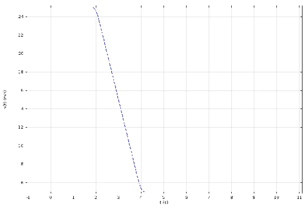
needs to be increased. Using a vented brake disc will increase the surface area because there is an additional surface area exposed to atmosphere which will lead to a better cooling (Belhocine et al. 2014).Finite element method gives a possibility to analyze heat conduction in disc brake system. Our task was to study the heat generation and dissipation in a disc brake during a panic car braking for two seconds and following a release period of six seconds using COMSOL Multiphysics 5.0. The car (1600 kg) initially travels at 90 km/h. Suddenly, the driver hits the brakes for two seconds, and then releases the brakes for 6 seconds. The wheels are assumed not to skid against the road surface. Using 3D simulation, we have observed temperature changes on the brake disc during the braking and the cooling process after braking.
2. Materials and methods
2.1 Governing equations
The kinetic energy of the vehicle in motion can be expressed as:
2 2
1 2
1
(
)
2
E
m v
v
(2)where
m
is vehicle mass,v
1 initial velocity andv
2 is reduced velocity. If we neglect drag and other losses, the brakes retardation power is equal to the negative derivative of kinetic energy (Petinrin et al. 2012):2
2
(
)
( )
2
d mv
dv
P
mv
mR
t
dt
dt
(3)where
m
is vehicle mass,R
is wheel radius,
is angular velocity, and
is the angular acceleration.The friction force per unit area,
f
f is approximately constant over the surface area of eightpads (two pads per brake disc) and is directed opposite the brake disc velocity vector:
8
fv
d8
f( ) ( )
P
f dA
f
t
t
rdA
(4)Using the previous two equations, the frictional force can be determined as:
2
8
f mmR
f
r A
where
r
m is the distance between the center of the brake disc and the pad center of mass, and
is negative acceleration during retardation.The heat power generated on the contact area can be defined as:
2
f d 0
( , )
f
v ( , )
(
)
8
mmR
q r t
r t
r
t
r A
(6)The heat dissipation from the brake disc and pad surfaces to the surrounding air is described by convection and radiation as:
4 4
(
)
(
)
diss ref ref
q
h T
T
T
T
(7)where
h
is convective film coefficient,
is the material emissivity, and
is the Stefan-Boltzmann constant.2.2 Model definition
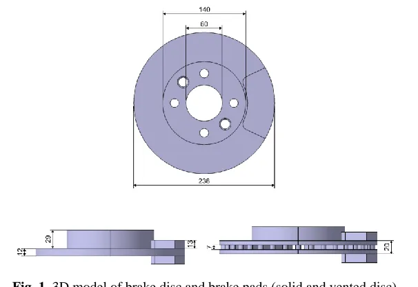
The model of the complete disc brake is generated using Catia v5 R18 software. The model of the full brake disc with the main dimensions is shown in Fig. 1.
Fig. 1. 3D model of brake disc and brake pads (solid and vented disc)
Meshing of the brake disc and brake pads has been done using Comsol Multiphysics 5.0. The complete mesh of the full disc consists of 77626 tetrahedral elements, while the complete mesh of the vented disc consists of 95341 tetrahedral elements.
Fig. 2. Velocity-Time graph
Brake discs are commonly manufactured of cast iron. This material has good thermo-physical characteristics. The material of brake pad is asbestos. Their material properties are given in Table 1.
Table 1. Material properties of brake disc and pad
3. Results and discussion
The 3D finite element analysis of the temperature of the brake disc during the braking was done using COMSOL Multiphysics 5.0. We used Heat transfer in solids module. Fig. 3 shows the temperature distribution for the full brake disc at different time steps.
Material properties Cast iron Asbestos
Density [kg/m3] 7870 2000
Heat capacity [J/(kgK)] 449 935
a) b)
c) d)
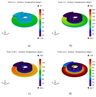
Fig. 3. The temperature distribution for solid disc at different time steps
The beginning of the braking process is characterized by temperatures of 72 °C in contact brake disc and pads. As the process of braking continues, the temperature rises quickly and reaches a maximum value of 182 °C. In addition, with this simulation we wanted to show how the brake disc cools after completing the braking. The temperature distribution at that point in time is shown in Fig. 3d. Fig. 4 shows the temperature distribution for the vented disc at four different time steps.
c) d)
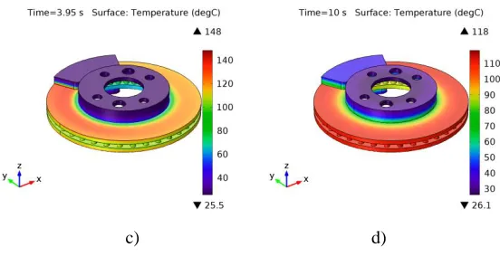
Fig. 4. The temperature distribution for vented disc at different time steps
The previous figure visually shows that the vented disc is less heated than the solid disc. Maximum temperature that is released in this process of braking is 166 °C (Fig. 4b). After releasing the brakes, after 6 seconds, the maximum value of temperature is 118 °C, which is substantially less than in the case of the solid disc. The reason for that is the space between the vanes, which increases heat dissipation from the disc.
Fig. 5. Temperature versus time
Fig. 5 shows the variation of temperature versus time during the braking process for solid and vented brake disc. The highest temperature occurs approximately 1 s after engaging the brake in the contact surface of the brake disc and the pads. At time t = 4s (end of braking), a maximum temperature of 157.9 °C is achieved on the solid disc. For the same time interval, the vented disc generates a temperature of 147.5 °C. It may be noted that the vented disc is a better solution because the heat is much better drained from its surface. Vanes geometry and their total number greatly affects the heat dissipation from the brake disc.
4. Conclusions
that the ventilated brake disc is a better solution, because it contains additional surfaces from which the heat dissipates. Disc brake design plays an important role in heat transfer. It would be interesting to see how the temperature distribution is influenced by various forms of vanes and their thickness. Our future research will go in that direction.
Извод
Термална анализа чврстог и вентилирајућег диска током процеса
кочења
S. Mačužić1, I. Saveljić1,2, J. Lukić1, J. Glišović1
and N. Filipović1,2
1Факултет инжењерских наука, Универзитет у Крагујевцу, Сестре Јањић 6, 34000 Крагујeвац, Србија
2Истраживачко-развојни центар за биоинжењеринг БиоИРЦ, 34000 Крагујевац, Србија *Главни аутор [email protected]
Резиме
Кочиони систем је један од најважнијих компоненти возила на путу. Овај систем има задатак да заустави возило или да га успори. Фрикционе кочнице, током процеса кочења, претварају кинетичку и потенцијалну енергију у термалну енергију (топлоту). Основне компоненте кочионих система, кочиони дискови и кочионе плочице, у кратком временском периоду апсорбују велику количину ослобођене топлоте (Travaglia et al. 2014). Апсорбована топлота мора бити, колико је могуће, ефикасно расута како би се осигурао нормалан рад система за кочење (Day et al. 1984). Висока температура током кочења може изазвати многе проблеме као што су термалне пукотине, прерано хабање, затим кочнице бледе и могућа је појава термичких вибрација (Lee 1999). У овом истраживању, моделиран је типичан кочиони систем који укључује кочиони диск и кочионе плочице. Користећи COMSOL Multiphysics 5.0, истражено је топлотно понашање две врсте дискова: чврстих - солид и вентилирајућих. Резултати показују да је вентилирајући диск много боље решење од чврстих дискова, јер се доста већа количина топлоте ослобађа са вентилирајућег диска за исто време.
Кључне речи: Кочиони диск, топлотна анализа, дисипација топлоте, COMSOL Multiphysics 5.0.
References
Belhocine А, Abu Bakar АR, Bouchetara M (2014). Numerical Modeling of Disc Brake System in Frictional Contact, Tribology in Industry, 36, 1, 49‐66.
Day AJ, Newcomb TP (1984). The Dissipation of Frictional Energy from the Interface of an Annular Disk Brake. Proceedings Institute of Mechanical Engineers 198(11): 201-209. Idusuyi N, Babajide I, Ajayi OK, Olugasa TT (2014). A Computational Study on the Use of an
Lee K (1999). Numerical Prediction of Brake Fluid Temperature Rise During Braking and Heat Soaking, SAE Technical Paper 1999-01-0483, doi:10.4271/1999-01-0483.
Limpert R (1975). The Thermal Performance of Automotive Disc Brakes, SAE Technical Paper 750873, doi:10.4271/750873.
Petinrin MO, Oji JO (2012). Numerical Simulation of Thermoelastic Contact Problem of Disc Brake with Frictional Heat Generation, New York Science Journal,5(10).
Talati F, Jalalifar S (2009). Analysis of heat conduction in a disk brake system, Heat and Mass Transfer, 45, 8, 1047–1059.