SELF TUNING CONTROLLERS FOR
DAMPING LOW FREQUENCY
OSCILLATIONS
SANGU RAVINDRA,
Associate Professor, Department of EEE, QISCET, Ongole. [email protected]
DR.V.C.VEERA REDDY,
Professor of EEE, S.V.University, Tirupathi. [email protected]
DR.S.SIVANAGARAJU,
Associate Professor, Department of EEE, JNTUK, Kakinada. [email protected]
Abstract: This paper presents a new control methods based on adaptive Neuro-Fuzzy damping controller and adaptive Artificial Neural Networks damping controller techniques to control a Unified Power Flow controller (UPFC) installed in a single machine infinite bus Power System. The objective of Neuro-Fuzzy and ANN based UPFC controller is to damp power system oscillations.Phillips-Herffron model of a single machine power system equipped with a UPFC is used to model the system. In order to damp power system oscillations, adaptive neuro-fuzzy damping controller and adaptive ANN damping controller for UPFC are designed and simulated. Simulation is performed for various types of loads and for different disturbances. Simulation results demonstrate that the developed adaptive ANN damping controller has an excellent capability in damping electromechanical oscillations which exhibits a superior damping performance in comparison to the neuro-fuzzy damping controller as well as conventional lead-lag controller.
Keywords: LFO; UPFC; SMIB; Neuro-Fuzzy damping Controller; ANN damping controller.
1. INTRODUCTION:
Nowadays, Flexible AC Transmission Systems (FACTS) technology is ultimate tool for getting the most out of existing equipment via fast control action and new capabilities [3], [17]. The most striking feature is the ability to directly control transmission line flows by structurally changing parameters of the grid, and to implement high gain type controllers based on fast switching. The UPFC is the most versatile FACTS device that can be used to the damp power system oscillations. The UPFC consists of two voltage source converters (VSC) each of them has two control parameters namely me, mb,δeand δb[2]. The UPFC used for power flow control, enhancement of transient stability, mitigation of system oscillations and voltage regulation [2]. A comprehensive and systematic approach for mathematical modeling of UPFC for steady-state and small signal (linearized) dynamic studies has been proposed in [11], [12], [14] and [19]. The other modified linearized Heffron-Philips model of a power system installed with UPFC is presented in [16]. For systems which are without power system stabilizer (PSS), excellent damping can be achieved via proper controller design for UPFC parameters. By designing a suitable UPFC controller, an effective damping can be achieved. It is usual that Heffron-Philips model is used in power system to study small signal stability. This model has been used for many years providing reliable results [7].
2. POWER SYSTEM MODELING WITH UPFC:
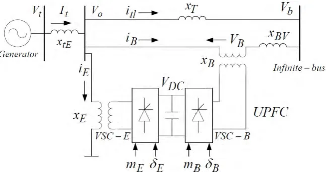
UPFC is one of the famous FACTs devices that is used to improve power system stability. Figure 1 shows a single machine infinite bus (SMIB) system (Heffron-Philips model of a power system installed with UPFC) with UPFC. It is assumed that the UPFC performance is based on pulse width modulation (PWM) converters. In figure 1 me, mband δe, δbare the amplitude modulation ratio and phase angle of control signal of each voltage source converter respectively, which are the input control signals of the UPFC.
Fig 1: Heffron-Philips model of a power system installed with UPFC
A linearized model of the power system can be used in studying power system oscillation stability and control. The dynamic model of UPFC is required in order to study the effect of UPFC on enhancing the small signal stability of power system. In this model the resistance and transient of the transformers of the UPFC can be ignored. The system’s dynamic equations of the UPFC can be written as [17]-[18]:
2 sin 2 cos 0 0 E dc E E dc E Eq Ed E E Etq Etd v m v m i i x x v v (1) 2 sin 2 cos 0 0 B dc B B dc B Bq Bd B B Btq Btd v m v m i i x x v v
(2)
Bq Bd B B dc B Eq Ed E E dc E dci
i
C
m
i
i
C
m
dt
dv
sin
cos
4
3
sin
cos
4
3
(3)The complete dynamic model of a single machine infinite bus power system equipped with a UPFC can be developed by combining equations (1) to (3) with the machine dynamic equations shown below.
=
o
H D
P
Pm e )/2
(
do fd
q
E
T
E
q
E
(
)
/
)
(
1
t to A A fd Afd
v
v
T
K
E
T
B B E E b c cb e c ce A b v A A vb A A e v A A ve A d b q d qb d e q d qe b p pb e p pe dc fd Q A vd A A A A A A d qd d d d pd o dc fd Q m m k k k k T k k T k k T k k T k k T k T k T k T k M k M k M k M k v E E k k k T k k T T k k T k k T k T T k T k M k M k M D M k v E E ' 0 ' 0 ' 0 ' 0 ' 9 8 7 6 5 ' 0 ' 0 ' 0 3 ' 0 4 2 1 ' 0 0 0 0 0 0 1 0 1 0 0 0 0 0 0 (5) Where ∆mE, ∆δE, ∆mB and ∆δBarethe variations of input control signals of the UPFC.
3. DESIGN OF DAMPING CONTROLLERS:
3.1. Lead-lag controller design
As mentioned before, in this study three different controllers have been used to damp LFO. The first one is conventional lead-lag controller. It consists of gain block, washout block, lead-lag compensator block. The washout block is considered as a high-pass filter, with the time constant TW. Without this block steady changes in input would modify the output. The value of TW is not critical and may be in the range of 1 to 20 seconds. In this study, the parameters obtained from lead-lag controller design that is presented in [15], were used.
3.2. Adaptive neuro-fuzzy controller design
Another controller is adaptive neuro-fuzzy controller. In this section, we will present the procedure of designing of the adaptive neuro-fuzzy controller. In this research, the neuro fuzzy controller has 2 inputs that are
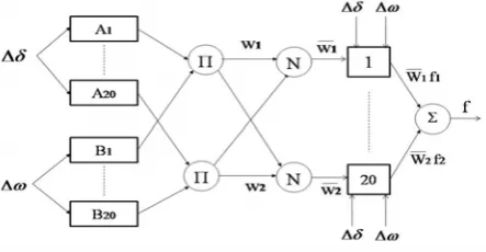
Δδ and Δω and it has 1 output that is f {ΔmE, ΔδE, ΔmB, ΔδB}. For each input 20 membership functions and also 20 rules in the rules base is considered. Figure 2 demonstrates the structure of adaptive neuro-fuzzy controller for a sugeno fuzzy model with 2 inputs and 20 rules [5].
Fig 2: ANFIS architecture for a two input Sugeno fuzzy model with 20 Rules
In fig 2, a sugeno fuzzy system has rule base, such rules are: 1. If Δδ is A1 and Δω is B1 then f1=p1 Δδ +q1 Δω+r1. 2. If Δδ is A2 and Δω is B2 then f2=p2 Δδ +q2 Δω+r2.
µAi and µBi are member ship functions of fuzzy set Ai and Bi for i = 1, 2,..., 20. While evaluating the rules, we choose product as logical AND gate. The controller could be designed by using following steps:
1. Weights are updated:
Wi = µAi (Δδ) µAi (Δω), i = 1,2,…,20. (6)
2. Calculate the output value: ) , ( ... ) , ( ) , ( ) , ( ... ) , ( ) , ( ) , ( 20 1 20 20 1 1 W W f W f W f (7)
(or) leaving the arguments out 20 1 20 20 1 1 ... ... W W f W f W f (8)
The above equation can be rewrite as
Where , 1,2,...,20 ... 20
1
1
i
W W
W Wi
The above relation is linear with respect to pi, qi, riand i =1,…,20. So parameters can be categorized into 2 sets: set of linear parameters and set of nonlinear parameters. Now Hybrid learning algorithm can be applied to obtain values of parameters. Hybrid learning algorithm is combination of linear and nonlinear parameters learning algorithm. Description for learning procedure can be found in [5]. This network is called adaptive by Jang and it is functionally equivalent to Sugeno type of a fuzzy system. It is not a unique presentation. With regard to the explanations presented and with the help of MATLAB software, adaptive neuro-fuzzy controller can be designed.
One of the advantages of using neuro-fuzzy controller is that we can utilize one of the designed controllers for instance Δmecontroller in place of the other controllers
3.3. Adaptive artificial neural networks controller design
Before the ANN can be used to adapt the controller gains in real time, it is necessary to determine a proper set of values for the connection weights .The process of reaching the connection weights is normally carried out off-line and is usually referred to as the training process. In the training process, we first compile a set of training patterns and store these training patterns in the training set. Each training pattern comprises a set of input data and the corresponding output data. A training pattern set of training patterns, which cover a wide range of operating conditions, is finally used to train the desired ANN [16]. It should be noted that we use two hidden layers. Main purpose of ANN is used for the reducing the error in the system, for that we are going to use training data method. In this method, we have to give both input values and desired output value for estimating the weight values, in that initial value taken as a random value. The input are ∆δ and ∆ω, desired output is the function of f € { ∆δb , ∆δe , ∆mb , ∆me }.For each input having 20 membership functions and Two rule base is considered.
ANN architecture for a two input sugeno model with two rules is shown in figure2.in which we are using the XOR gate.
Fig 3: ANN Architecture for a two input sugeno model with two rules
For the training data the error reducing method is the following steps are taken those are 1. Set the Learning Rate Parameter (ŋ) is greater than the one and error value E=0. 2. First Layer k =1.
3. Calculate the output value fi (n) = tansig (<Wi (µ(∆δ )+µ(∆ω) )>)+ r ;for i=1,2,…20. 4. Calculate error E=E+1/2||f - fi (n)||2.
5. Weights are updated Wi+1 = Wi + ŋ (f-tansig(<Wi (µ(∆δ )+µ(∆ω))>) + r); for i=1,2..20. 6. Check error E is not zero, then take the layer value as k =k+1,
7. Repeat the above process until when the error E as zero.
From above process we get the desired output function, the output function
f =(1-e-(Wi (µ(∆δ )+µ(∆ω))+r) /(1+e-(Wi (µ(∆δ )+µ(∆ω))+r) . The range of output function is -1 to +1.
4. SIMULATION RESULTS:
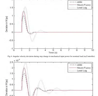
In this research, two different cases are studied. In the first case mechanical input power and in the second case reference voltage has step change and deviation in ω (Δω) and deviation in rotor angle δ (Δδ) is observed. The parameter values of system are gathered from Appendix. In first case, step change in mechanical input power is studied. Simulations are performed when mechanical input power has 10% increase (ΔPm=0.1 pu) at t = 1s. Simulation results for different types of loads and controllers (ΔmE, ΔδE, ΔmB, ΔδB) and step change in mechanical input power are shown in figures 4 to 8.
Fig 4: Angular velocity deviation during step change in mechanical input power for nominal load (meController).
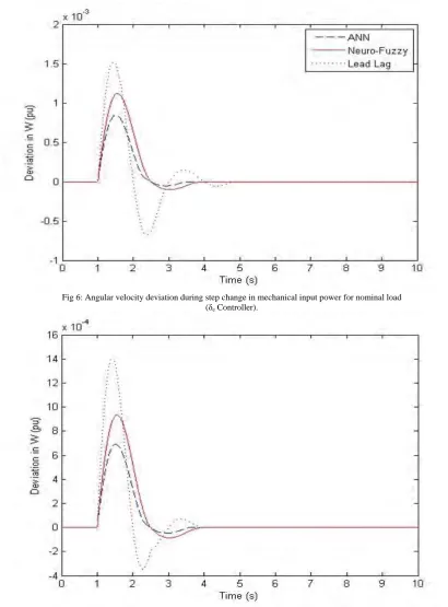
Fig 6: Angular velocity deviation during step change in mechanical input power for nominal load (δe Controller).
Fig 8: Angular velocity deviation during step change in mechanical input power for nominal load (δb Controller).
As it can be seen from figures 4 to 8, conventional lead-lag controller response is not as good as compared with both adaptive ANN damping controller response and Adaptive neuro-fuzzy controller response. Also Settling time decreases quickly in adaptive ANN damping controller when compared with adaptive neuro-Fuzzy Controller and conventional lead-lag controller. In addition maximum overshoot has decreased in adaptive ANN damping controller when compared with adaptive neuro-Fuzzy Controller and conventional lead-lag controller.
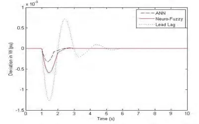
In second case, simulations were performed when reference voltage has 5% increase (ΔVref =0.05 pu) at t=1s. Figure 9 demonstrates simulation result for step change in reference voltage, under nominal load and for
δb Controller.
Consequently simulation results show that adaptive ANN damping controller successfully increases damping rate and decreases the amplitude of low frequency oscillations when compared with adaptive neuro-fuzzy controller and conventional lead-lag controller.
Results comparison between conventional lead-lag controller, adaptive neuro-fuzzy controller and the proposed adaptive ANN damping controller for the UPFC indicates that the proposed adaptive ANN damping controller has less settling time and less overshoot when compared with adaptive neuro-fuzzy controller and the conventional lead-lag controller.
5. CONCLUSIONS:
With regard to UPFC capability in transient stability improvement and damping LFO of power systems, an adaptive ANN damping controller for UPFC was presented in this paper. The controller was designed for a single machine infinite bus system. Then simulation results for the system including adaptive ANN damping controller were compared with simulation results for the system including adaptive neuro-fuzzy controller and conventional lead-lag controller. Simulations were performed for different kinds of loads. Comparison showed that the proposed adaptive ANN damping controller has good ability to reduce settling time and reduce amplitude of LFO.
6. REFERENCES:
[1] Banejad,M; Dejamkhooy ,A.M;Talebi,N(2008): " Fuzzy Logic Based UPFC Controller for Damping Low Frequency Oscillations of Power Systems", 2nd IEEE International Conference on Power and Energy, pp. 85-88.
[2] Gyugyi, L; Schauder, C.D; Williams, S.L; Rietman, T.R; Torgerson, D.R; Edris, A (1995): "The Unified Power Flow Controller: A New Approach to Power Transmission Control", IEEE Trans., pp. 1085-1097.
[3] Hingorani, N.G; Gyugyi, L (2000); Understanding FACTS: Concepts and Technology of Flexible AC Transmission System, IEEE Press.
[4] HSU, Y.Y; JENG, L.H. (1992): “Analysis of torsional oscillations using an artificial neural network”. Presented at the IEEEiPES winter meeting, paper 92 WM 003-4EC.
[5] Jyh-Shing Roger Jang; Chuen-Tsai Sun; Eiji Mizutani (1997): " Neuro-fuzzy and soft computing: a computational approach to learning and machine intelligence", Prentice- Hall.
[6] Karbalaye Zadeh;Khatami, Lesani, V; Ravaghi,H; H. A.(2009): " A fuzzy control strategy to damp multi mode oscillations of power system considering UPFC", 8th International Conference on Advances in Power System Control, Operation and Management, , p.1. [7] Kundur, p:"Power System Stability and Control", McGraw-Hill.
[8] K.P; Dash; Mishra,S ; Panda,G (2000): "Damping multimodal power system oscillation using a hybrid fuzzy controller for series connected FACTS devices", IEEE Trans. on Power Systems, Vol. 15, pp. 1360 -1366.
[9] Lo, K. L; Ma, T.T; Trecat, J; Crappe, M (1998):“A novel power control concept using ANN based multiple UPFCs scheme,” Pro. EMPD ’98, Singapore, pp. 570–575.
[10] Ma, T.T (2009): “Multiple Upfc Damping Control Scheme Using Ann Coordinated Adaptive Controllers”, Asian Journal of Control, Vol. 11, No. 5, pp. 489-502.
[11] Nabavi-Niaki, A; Iravani, M.R (1996): “Steady-state and Dynamic Models of Unified Power Flow Controller (UPFC) for Power System Studies.”, IEEE Transactions on Power Systems, Vol 11, p 1937.
[12] Noroozian, M; Angquist, L; Ghandari, M; Anderson, G (1997): “Use of UPFC for optimal power flow control”, IEEE Trans. on Power Systems, Vol. 12, No. 4, pp. 1629–1634.
[13] Oudalov,A; Cherkaoui,R; Germond,A.J (2001): "Application of fuzzy logic techniques for the coordinated power flow control by multiple series FACTS devices", IEEE Power Engineering Society International Conference, pp. 74 – 80.
[14] Smith, K.S; Ran, L; Penman, J (1997): “Dynamic Modeling of a Unified Power Flow Controller.”, IEE Proceedings-C, Vol 144, p.7. [15] Tambey, N; Kothari, M.L (2009):” Damping of power system oscillations with unified power flow controller (UPFC)”, IEE
Proc.-Gener. Transm.Distrib. Vol. 150, No. 2.
[16] Wang, H.F (1999): “Damping Function of Unified Power Flow Controller.”, IEE Proceedings-C, Vol 146, No 1, p 81.
[17] Wang, H.F; Swift, F.J (1997):" A Unified Model for the Analysis of FACTS Devices in Damping Power System Oscillations Part I: Single-machine Infinite-bus Power Systems", IEEE Transactions on Power Delivery, Vol. 12, No. 2, pp.941-946.
[18] Wolanki; Galiana, F.D; McGillis, D; Joos, G (1997): “Mid-Point Sitting of FACTS Devices in Transmission Lines,” IEEE Transactions on Power Delivery, Vol. 12, No. 4, pp.1717-1722.
APPENDIX
Generator: M = 2H = 8.0MJ / MVA, D=0.0, T’do = 5.044s, Xd = 1.0 pu, Xq = 0.6pu, X’d = 0.3pu Exciter (IEEE Type ST1): KA=100, TA=0.01s
Reactances: XlE = 0.1pu, XE = XB = 0.1pu XBv= 0.3pu, X e = 0.5pu Operation Condition: Pe = 0.8pu, Vt = 1pu, Vb = 1pu