72 |
P a g e
DECOUPLED DQ-CURRENT CONTROL OF GRID-TIED
VOLTAGE SOURCE CONVERTERS
Aluru Venkata Siva Sainadh
1, Sravan Kumar.Dasari
2M.Venkateswara Reddy
31
PG Student, Department of EEE,
Vikas Group of Institutions
, Nunna, Vijayawada, AP, (India)
2
Associate Professor, Dept. of EEE,
Vikas Group of Institutions
, Nunna, Vijayawada, AP, (India)
3
Associate Professor, Dept. of EEE,
Vikas Group of Institutions
, Nunna, Vijayawada, AP, (India)
ABSTRACT
This paper presents an approach for the connection of a photovoltaic generator to the utility grid. A theoretical analysis, modeling, controlling and a simulation of a grid connected photovoltaic system using output LCL filters are described in detail. In order to reduce the complexity of the system, a linear voltage and current controllers have been developed for a three phase grid connected inverter. By this way, the inverter control system is simplified from third-order to first-order, and the close loop control system can easily be optimized for minimum steady-state error and current harmonic distortion. It utilizes the multi-input multi-output (MIMO) nonparametric model of the system along with a high-order linearly parameterized MIMO controller to form an open-loop transfer function matrix. Minimizing the second norm of the error between the open-loop transfer function matrix and a desired one, the coefficients of the controller are optimally determined. The characteristics of the inverter system with the proposed controller are investigated and compared with the traditional strategy.
Index Terms—Convex Optimization, Damping, High-Order Controller, LCL-Filter, Loop Shaping, Micro
Grid, Resonance, Vector Control, Voltage-Source Converter (VSC)
I. INTRODUCTION
Renewable energy sources such as solar energy make increasing contributions to electric utility networks. Those
sources are commonly coupled to the grid through a pulse width modulation inverter and filter [1]. Different
output filter topologies are commonly used to interface inverter to the network, namely the L and the LCL filter.
The use of the filter coupling the inverter to the grid reduces the high frequency pollution of the grid that can
disturb loads [2]. They provide to the grid a nearly sinusoidal line current waveforms and a low line current
distortion [3-5]. Of all filters used in the field of power electronic applications, the LCL filter is currently the
most frequently used topologies [6]. Traditionally, L-filter is used as the interface between the grid network and
the grid-connected voltage source inverters (VSI). With the L-filter, high switching frequency must be used to
obtain high dynamic performance and sufficient attenuation of harmonics caused by the PWM. In contrast, the
alternative LCL form of low-pass filter offers the potential for improved harmonic performance at lower
switching frequencies, which is a significant advantage in higher-power applications [1], (e.g. fuel cell, wind
generations). However, systems incorporating LCL filters are of third order, and they require more complex
current control strategies to maintain system stability and are more susceptible to interference caused by grid
voltage distortion because of resonance hazards and the lower harmonic impedance to the grid.
This paper proposes a vector control strategy for the LCL filter-based grid-connected VSCs that has inherent
73 |
P a g e
strategy is able to fully decouple the dq-axes of the current. The design procedure shapes the open-loop andclosed-loop transfer function matrices of the LCL-filter-based system. This is in contrast with the conventional
approaches that design the controller matrix assuming an L-filter-based system. The proposed controller
guarantees system stability and provides satisfactory and robust performance over a wide range of operating
points. The elements of the controller matrix have an integrator similar to PI-controllers; however, they have
more zeros, which permit the controller matrix to compensate for the potentially unstable poles of the
LCL-filter-based system
II. STUDY SYSTEM DESCRIPTION
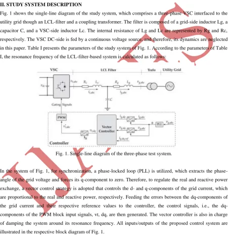
Fig. 1 shows the single-line diagram of the study system, which comprises a three-phase VSC interfaced to the
utility grid though an LCL-filter and a coupling transformer. The filter is composed of a grid-side inductor Lg, a
capacitor C, and a VSC-side inductor Lc. The internal resistance of Lg and Lc are represented by Rg and Rc,
respectively. The VSC DC-side is fed by a continuous voltage source, and therefore, its dynamics are neglected
in this paper. Table I presents the parameters of the study system of Fig. 1. According to the parameters of Table
I, the resonance frequency of the LCL-filter-based system is calculated as follows:
Fig. 1. Single-line diagram of the three-phase test system.
In the system of Fig. 1, for synchronization, a locked loop (PLL) is utilized, which extracts the
phase-angle of the grid voltage and forces its q-component to zero. Therefore, to regulate the real and reactive power
exchange, a vector control strategy is adopted that controls the d- and q-components of the grid current, which
are proportional to the real and reactive power, respectively. Feeding the errors between the dq-components of
the grid current and their respective reference values to the controller, the control signals, i.e., the
dq-components of the PWM block input signals, vt, dq, are then generated. The vector controller is also in charge
of damping the system around its resonance frequency. All inputs/outputs of the proposed control system are
illustrated in the respective block diagram of Fig. 1.
III. HIGH-ORDER DAMPING VECTOR CONTROL STRATEGY
In this section, the design procedure of the damping vector control strategy for LCL-filter-based VSCs is
detailed, which is based on a constrained optimization-based loop shaping method. It uses the MIMO
nonparametric model of the system, i.e., G(jω), along with a linearly parameterized MIMO controller, i.e.,K(z),
74 |
P a g e
and the decoupling requirements, a desired open-loop transfer function matrix, i.e.,LD(s), is also formed, and itsdiagonal and off diagonal elements are determined. Minimizing the second norm of the error between the
open-loop transfer function matrix and the desired one, the coefficients of the controller are optimally determined. To
ensure the stability and the required dynamic performance of the closed-loop system, the minimization problem
is subject to constraints. The design procedure is divided into three main steps: (1) the determination of the
required nonparametric model, (2) the determination of the class of the controller, and (3) solving the
optimization problem and finding the optimal coefficients of the controller. In the following, the steps are
detailed.
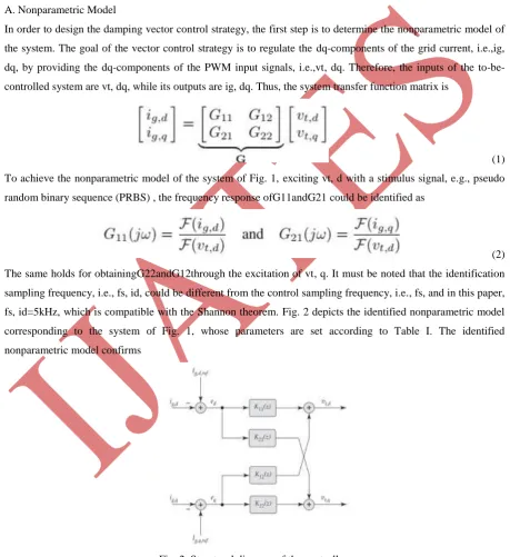
A. Nonparametric Model
In order to design the damping vector control strategy, the first step is to determine the nonparametric model of
the system. The goal of the vector control strategy is to regulate the dq-components of the grid current, i.e.,ig,
dq, by providing the dq-components of the PWM input signals, i.e.,vt, dq. Therefore, the inputs of the
to-be-controlled system are vt, dq, while its outputs are ig, dq. Thus, the system transfer function matrix is
(1)
To achieve the nonparametric model of the system of Fig. 1, exciting vt, d with a stimulus signal, e.g., pseudo
random binary sequence (PRBS) , the frequency response ofG11andG21 could be identified as
(2)
The same holds for obtainingG22andG12through the excitation of vt, q. It must be noted that the identification
sampling frequency, i.e., fs, id, could be different from the control sampling frequency, i.e., fs, and in this paper,
fs, id=5kHz, which is compatible with the Shannon theorem. Fig. 2 depicts the identified nonparametric model
corresponding to the system of Fig. 1, whose parameters are set according to Table I. The identified
nonparametric model confirms
Fig. 2. Structural diagram of the controller.
the resonance phenomenon at frequencies around the predicted resonance frequency of 1677 Hz. Therefore, the
controller matrix must be chosen and designed such that in the closed-loop system, the gains at frequencies
75 |
P a g e
B. Controller Class
The vector control strategy is responsible for regulating the dq-components of the grid current through
manipulating the dq-components of VSC terminal voltage, i.e., vt, dq. Therefore, to control such a system, a 2
×2 controller is required. A generic form of such a multivariable discrete-time controller in the z-domain is
given by
(3)
Where d and eq are the current errors in the d- and q-axes, respectively. The structural diagram of the controller
is depicted in Fig. 2. Conventional vector control strategies for L-filter-based VSCs utilize PI-controllers as the
elements of the controller matrix [2], [3]. In such systems, only one dominant pole exists in each axis, which
could be compensated by the zero of the utilized PI-controllers. In LCL-filter-based systems, however, this is no
longer valid as more poles are introduced by the additional passive LC elements. Thus, if PI-controllers are used
for the vector control of LCL-filter-based, all poles of the system may not be compensated, and therefore,
damping strategies are required to attenuate the effects of the uncompensated poles. In this paper, high-order
controllers are utilized as the elements of the controller in order to compensate for all poles of the
LCL-filter-based system such that no extra damping strategies are required. Thus, each element of the controller matrix of
(4) is a 5th-order controller in the z-domain. For example, K11is given by
(4)
In which the vector ρ contains the controller matrix coefficients as follows:
(5)
Therefore, the open-loop transfer function matrix of the LC L filter-based system is given by
(6)
C. Optimization-Based Loop Shaping
The loop shaping of the open-loop transfer function matrix, i.e., L, is carried out by minimizing the square
second norm of the error between the individual entries of Land a desired open-loop transfer function matrix,
LD(s). Consequently, the control design procedure turns into an optimization problem as follows
(7)
The desired open-loop transfer function matrix, LD, is chosen to meet the system requirements, e.g., satisfactory
dynamic response and reduced coupling between the outputs, i.e., ig, d and ig, q. In this paper, the desired
76 |
P a g e
(8)
In which ωc= 1200rad/s. Note that the bandwidth of the closed-loop system is manipulated by the choice of ωc.
In order to ensure the stability and also the dynamic performance of the to-be-designed controller, the
minimization problem is subject to several constraints. The reference proves that to shape the sensitivity
function of the closed loop system, the minimization problem must be subject to the following linear constraints:
(9)
whereW1 (jω) is a weighting filter. In this paper, W1 (jω) = 0.5, which guarantees a gain margin of at least 2
and a phase margin of greater than 29◦. Moreover, to ensure the stability of the closed-loop system, the
minimization problem must satisfy the generalized Nyquist stability criterion. Therefore, as proved, the
minimization problem must also satisfy the following constraints.
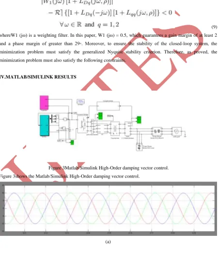
IV.MATLAB/SIMULINK RESULTS
Figure 3Matlab/Simulink High-Order damping vector control.
Figure 3shows the Matlab/Simulink High-Order damping vector control.
77 |
P a g e
(b)&(c)(d)
Fig.4. Simulation response of the system of the reference change in the d-axis while the LCL-filter parameters
contain uncertainties: (a) the three-phase load voltage, (b) the three-phase grid current, (c) the three-phase
converter current. (d) The d-and q-components of the grid current.
Reference Tracking in d-Axis: The reference value of the q-axis is kept constant at−6 A while the reference
value of the d-axis steps up from−2 A to 5 A at the time instant t=20ms implying a change in the active power
flow as well. Fig. 4(a) depicts the three-phase grid voltage, which remains unchanged during the reference
tracking change. Fig. 4(b) and (c) show the three-phase converter and grid currents, respectively. The
dq-components of the grid current, which are regulated by the high-order vector control strategy at their respective
values, are also shown in Fig. 4(d). The latter confirms that upon the step-change in the d-axis, no resonance
occurs in the system, and the reference value is tracked in almost 1 ms. Moreover, upon the step-change in the
d-axis, the q-axis remains unchanged proving the decoupling capability of the proposed controller.
Subsequent to the step-change, the grid voltage experiences minor transients due to its internal impedance. In
78 |
P a g e
changes with zero steady-state error. Moreover, the currents do not contain resonance frequency ripples, whichconfirm the capability of the controller in terms of closed-loop system damping. In addition, it can be observed
that in all cases, the experimental results are in very good agreement with the respective simulation results.
Figure5 Matlab/Simulink High-Order damping vector control with q-axis
Figure5 shows the Matlab/Simulink High-Order damping vector control with q-axis
(a)
79 |
P a g e
(d)Fig.6. Simulation response of the system of the reference change in the q-axis while the LCL filter parameters
contain uncertainties: (a) the three-phase grid voltage, (b) the three-phase grid current, (c) the three-phase
converter current. (d) The d-and q-components of the grid current
Reference tracking in q-Axis: Another reference tracking test is carried out to evaluate the performance of the
controller upon step-changes in the reference value of the q-axis while the reference value of
thed-axisisfixedat6A. The reference value of the q-axis is stepped up from 0 to 8 A at the time instant t=20ms. Fig.
6(a)–(c) depict the three phase grid voltage, grid current, and converter current, respectively. Prior and
subsequent to the step-change, the grid voltage remains unchanged, while the grid and converter currents are
changed by the controller. Fig. 6(d) shows the dq-components of the grid current, which are regulated at their
requested set-points. Upon the step-change in its reference value, the q-component reaches its final value in
almost 1 ms, while the d-component is practically unaffected due to the decoupling effect of the controller.
Moreover, the resonance is experienced neither upon the change of the reference signal nor in the steady-state
operation.
V.CONCLUSION
A digital vector control strategy for the LCL-filter-based grid-connected VSCs is proposed in this paper. To
damp the resonance phenomenon of the LCL-filter, a MIMO controller matrix is adopted, whose elements are
linearly parameterized high-order controllers with integrators. Contrary to the existing vector control schemes
for VSCs with LCL-filters, the proposed approach does not require extra damping methods. Moreover, the
dynamic performance of the proposed approach is similar to the existing ones while its axis-decoupling
capability is superior. The design procedure of the proposed controller is based on loop shaping and has three
main steps: (1) attaining a nonparametric model of the system, (2) determining the class of the to-be-designed
controller, and (3) solving a constrained convex optimization problem.Compared with the traditional strategies,
the new control strategy has the superiority, and it is easy to be fulfilled. Thus, the new current control strategy
80 |
P a g e
REFERENCES
[1] O. Senturk, L. Helle, S. Munk-Nielsen, P. Rodriguez, and R. Teodorescu, “Power capability investigation based on electro thermal
models of press pack IGBT three-level NPC and ANPC VSCs for multi mega watt wind turbines,” IEEE Trans. Power Electron., vol.
27, no. 7, pp. 3195–3206, Jul. 2012.
[2] B. Bahrani, A. Karimi, B. Rey, and A. Rufer, “Decoupled q-current control of grid-tied voltage source converters using nonparametric models,” IEEE Trans. Ind. Electron., vol. 60, no. 4, pp. 1356–1366, Apr. 2013.
[3] B. Bahrani, S. Kenzelmann, and A. Rufer, “Multivariable-PI-based dq current control of voltage source converters with superior axis
decoupling capability, ”IEEE Trans. Ind. Electron., vol. 58, no. 7, pp. 3016–3026, Jul. 2011.
[4] B. Bahrani, A. Rufer, S. Kenzelmann, and L. Lopes, “Vector control of single-phase voltage-source converters based on fictive-axis emulation,” IEEE Trans. Ind. Appl., vol. 47, no. 2, pp. 831–840, Mar./Apr. 2011.
[5] M. Liserre, R. Teodorescu, and F. Blaabjerg, “Stability of photovoltaic and wind turbine grid-connected inverters for a large set of grid
impedance values,” IEEE Trans. Power Electron., vol. 21, no. 1, pp. 263–272, Jan. 2006.
[6] P. Sun, C. Liu, J.-S. Lai, and C.-L. Chen, “Grid-tie control of cascade dual buck inverter with wide-range power flow capability for
renewable energy applications, ”IEEE Trans. Power Electron., vol. 27, no. 4, pp. 1839–1849,
Apr. 2012.
[7] R. Teodorescu, M. Liserre, and P. Rodriguez,Grid Converters for Photovoltaic and Wind Power Systems. Hoboken, NJ, USA: Wiley,
2011.
[8] H. Akagi and R. Kondo, “A transformer less hybrid active filter using a three-level Pulse width Modulation (PWM) converter for a
medium voltage motor drive,” IEEE Trans. Power Electron., vol. 25, no. 6, pp. 1365–1374, Jun. 2010.
[9] V. Coroban-Schramel, I. Boldea, G.-D. And reescu, and F. Blaabjerg, “Active-flux-based motion-sensor less vector control of biaxial
excitation generator/motor for automobiles, ”IEEE Trans. Ind. Appl., vol. 47, no. 2, pp. 812–819, Mar./Apr. 2011.
[10] J. Chivite-Zabalza, M. Rodriguez Vidal, P. Izurza-Moreno, G. Calvo, and D. Madariaga, “A large power, low-switching-frequency
voltage source converter for FACTS applications with low effects on the transmission line,” IEEE Trans. Power Electron., vol. 27, no.
12, pp. 4868–4879, Dec. 2012.