IMPLEMENTATION OF LOAD BALANC
Computer, Scie
ARTICLE INFO ABSTRACT
Nowad downti Bank X the tec XYZ c method
Copyright©2016, Raka Yusuf. This is an open access article distributed under the Creative Commons Att distribution, and reproduction in any medium, provided the original work is properly cited.
INTRODUCTION
Business development leads business app company grows up, it must be ready to de application. The development is not on application according to the business needs b reliable level of application availability. become the most important things when your c has a great business. The application needs to time. There is no excuse for down time. Fu at the high-availability network infrastructu systems. In addition, it is necessary also t network devices and servers used, so t happens then the business does not stop be back up. To maximize this, the devices used load sharing and automatic failover. Load sh help divide the existing traffic of application are used so that the device is not burdened of traffic. While automatic failover is used fails, it can automatically move to the ne disrupting the activity of the applications disrupt business.
*Corresponding author: Raka Yusuf,
Computer, Science Faculty Mercubuana University,
ISSN: 0975-833X
Article History:
Received 22nd June, 2016
Received in revised form 25th July, 2016
Accepted 17th August, 2016
Published online 30th September,2016
Key words:
Load balancing, Automatic Failover, F5,
Internet Banking.
Citation: Raka Yusuf, 2016. “Implementation of load balanc
Research, 8, (09), 38692-38698.
RESEARCH ARTICLE
LOAD BALANCING AND AUTOMATIC FAILOVER FOR
INTERNET BANKING
*
Raka Yusuf
Science Faculty Mercubuana University, Indonesia
ABSTRACT
days application needs to always on and never get dow ime, you will lose your business. Load balancing and auto XYZ choose to support their new application, Internet Bank hnology from F5 with their product IP LTM and BIG-can perform well and never get down time anymore becaus d for the traffic.
is an open access article distributed under the Creative Commons Attribution License, which distribution, and reproduction in any medium, provided the original work is properly cited.
pplication. When a evelop more in its nly to adjust the but also to make a The availability r company already to be ready all the ulfillment is aimed ure and application the redundancy of that if something ecause there is no must have feature sharing is used to ns on devices that ed with the amount ed when one server xt device without used so as not to
y, Indonesia.
Bank XYZ want to implemen internet banking which is the n They want to make the b application. To fulfill their go device that have load sharing a The process for making the inf above is starts with an asses network devices to obtain prel that exist today.
It will be the basis for laying a that will support the desired location found that in fact it has already had load sharing fea maximized because the device sharing, there are must be min need to share the traffic. Th process of incoming traffic. T also because the devices is on system will failed and the bus team also found that the ne performing failover not only f Internet banking but for support the passage of the inter
Available online at http://www.journalcra.com
International Journal of Current Research Vol. 8, Issue, 09, pp.38692-38698, September, 2016
INTERNATIONAL
load balancing and automatic failover for application internet banking
z
OVER FOR APPLICATION
esia
wn time. If your application has omatic failover become the way that king. In the implementation they use -IP GTM. Internet Banking in Bank se they have failover and balancing
ribution License, which permits unrestricted use,
nt their new application named new generation from the old one. business grows up with this goals, they want to implement a g and automatic failover feature. frastructure that can be work as ssment of the overall existing eliminary data on the conditions
and also the addition of devices d goal. The team observe the s been using the technology that atures in it. But its use is not ice is only one. In making load nimal two devices because they hey will switch in taking the There is not failover mechanism only one so if it is failed, the siness will stop. In addition, the eeds of the case study site in for their primary application is other applications which can rnet banking application.
INTERNATIONAL JOURNAL OF CURRENT RESEARCH
THE THEORY
Load Balancing
Load balancing is an even division of processing work between two or more computers and/or CPUs, network links, storage devices or other devices, ultimately delivering faster service with higher efficiency. Load balancing is accomplished through software, hardware or both, and it often uses multiple servers that appear to be a single computer system (also known as computer clustering). Management of heavy Web traffic relies on load balancing, which is accomplished either by assigning each request from one or more websites to a separate server, or by balancing work between two servers with a third server, which is often programmed with varied scheduling algorithms to determine each server’s work. Load balancing is usually combined with failover (the ability to switch to a backup server in case of failure) and/or data backup services. System designers may want some servers or systems to share more of the workload than others. This is known as asymmetric loading. Large telecommunications companies and others with extensive internal or external networks may use more sophisticated load balancing to shift network communications between paths and avoid network congestion. Results include improved network reliability and/or the avoidance of costly external network transit. [https://www.techopedia.com/ definition/ 4197/load-balancing]
Automatic Failover
Automatic failover is a resource that allows a system administrator to automatically switch data handling to a standby system in the event of system compromise. Here, automatic describes the failover process. By definition, most failover processes are programmed to operate automatically. Automatic failover is a best practice for systems that experience damage or lose vital connectivity during various scenarios, such as storms and natural disasters. Organizations may use automatic failover systems to protect against data loss in such situations, which are often referred to as disaster recovery plans or emergency planning. An automatic failover system allows for immediate off-site handling of database and server setups, ensuring seamless operations if an original system site is under attack by a storm or other disaster [https://www.techopedia.com/definition/27075/automatic-failover].
Round Robin Algorithm
As name implies, it is simplest load balancing algorithm uses the time slicing mechanism. It works in the round trip where a time is divided into slices and is allotted to each node. Each node has to wait for their turn to perform their task. This algorithm has less complexity as compared to the other two algorithms. Open source simulation software knows as cloud analyst uses this algorithm as default algorithm in the simulation. This algorithm has less complexity as compared to the other two algorithms. This algorithm simply assigns the jobs in round robin fashion without considering the load on different machines.
Though the algorithm is very simple, there is an additional load on the scheduler to decide the size of time slice and it has longer average waiting time, higher context switches higher turnaround time and low throughput [Ajit and Vidya, 20133]
OVERVIEW OF PRODUCT AND SOLUTION
A load balancer is a device that acts as a reverse proxy and distributes network or application traffic across a number of servers. Load balancers are used to increase capacity (concurrent users) and reliability of applications. They improve the overall performance of applications by decreasing the burden on servers associated with managing and maintaining application and network sessions, as well as by performing application-specific tasks. Load balancers are generally grouped into two categories: Layer 4 and Layer 7. Layer 4 load balancers act upon data found in network and transport layer protocols (IP, TCP, FTP, UDP). Layer 7 load balancers distribute requests based upon data found in application layer protocols such as HTTP.
Requests are received by both types of load balancers and they are distributed to a particular server based on a configured algorithm. Some industry standard algorithms are:
Round robin
Weighted round robin
Least connections
Least response time
Layer 7 load balancers can further distribute requests based on application specific data such as HTTP headers, cookies, or data within the application message itself, such as the value of a specific parameter. Load balancers ensure reliability and availability by monitoring the "health" of applications and only sending requests to servers and applications that can respond in a timely manner [https://f5.com/glossary/load-balancer] High availability refers to the ability of a BIG-IP® system to process network traffic successfully. The specific meaning of high availability differs depending on whether you have a single BIG-IP device or a redundant system configuration:
Single device
When you are running the BIG-IP system as a single device (as opposed to a unit of a redundant system), high availability refers to core services being up and running on that device, and VLANs being able to send and receive traffic. For information on configuring a single device for high availability, see Configuring fail-safe. The remainder of this chapter is not applicable to systems configured as single devices.
Redundant system configuration
system and a pool of routers, and VLANs on the system being able to send and receive traffic. For information on configuring a redundant system for high availability, see the remainder of this chapter. A redundant system is a type of BIG-IP® system configuration that allows traffic processing to continue in the event that a BIG-IP system becomes unavailable. A BIG-IP redundant system consists of two identically-configured BIG- IP units. When an event occurs that prevents one of the BIG- IP units from processing network traffic, the peer unit in the redundant system immediately begins processing that traffic, and users experience no interruption in service.
Infrastructure Design
Implementation is done by using the BIG-IP Local Traffic Manager. The device BIG-IP Local Traffic Manager is a network device that serves to organize and manage data traffic either towards or coming out of multiple device servers or networks. The device server or network can be a web server, cache servers, routers, firewalls and proxy servers. With the F5 LTM is the integrated application system is expected to be more reliable, higher value of high availability and reduce server load and bandwidth. The main feature that will be implemented is Analytics (also called Application Visibility and Reporting). Analytics (also called Application Visibility and Reporting) is a module on BIG-IP ® system that you can use to analyze the performance of web applications. AVR provides detailed metrics such as transactions per second, client server and latency, response time and throughput, as well as sessions. You can view metrics for applications, virtual servers, pool, URLs, and additional detailed statistics on traffic of applications running through the BIG-IP system.
[image:3.595.316.555.501.635.2]Transaction Counter to the response code, user agent, HTTP methods, and IP address provide statistical analysis of traffic going through the system. With these AVR we can capture traffic for inspection and have the feature to send alerts so we can troubleshoot more easily. Moreover, it will also feature implemented Global Traffic Manager (GTM). Global Traffic Manager (GTM) This increases the performance and availability of applications by directing the user to the data center nearest or best-performing data center. Using the high-performance features of DNS, BIG-IP GTM has a high level scalability and can secure DNS infrastructure from DDoS attacks, and provide real-time complete DNSSEC solution. GTM can be configured as a full- proxy and DNS server.
Figure 1. Infrastructure Design
Each server F5 BIG-IP LTM has an Ethernet connection to each switch DMZ as much as 2 pieces.
The connections are made So that the total bandwidth Ether Channel obtained becomes large. Vlan in the DMZ switch that is configured VLAN tag (4, 101, 105, 109, and 140) were allocated to VLAN server. Additionally, both servers F5 BIG-IP LTM is configured active-standby so that if one of the servers F5 BIG- IP LTM impaired then the user can still access the virtual servers provided by F5 BIG-IP LTM is. As for F5 BIG-IP GTM is configured active-active, either the existing resource record in the Zone List, and PTR which is in Zone List, all will sync.
The Configuration
The basic configuration includes the hostname, Domain Name, Management IP Address and mask, Self IP Address VLAN External, Self IP Address VLAN Internal, Self IP Address VLAN new_ibank (application internet banking), Self IP Address VLAN synchronization, Self IP Address VLAN Management, DNS Servers, NTP Servers, Authentication Server.
Parameter Configuration Server for Load Balancing in F5 LTM
Parameter Configuration Server for Load Balancing in F5 LTM Virtual Server Host Name is the Pool Name, Host Port and Protocol, Load Balancing Pool and listening ports, and Load Balancing Method used is round robin.
High Availability Configuration in F5 LTM
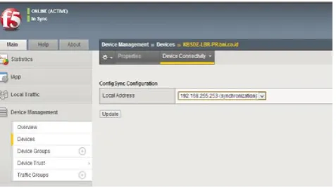
Configuration is done by making access to the system menu and then to high availability by using an administrator account on both devices F5 LTM. Then from the menu, choose the vlan synchronization administrator that was created earlier. Configuration synchronization between the two devices F5 is done manually through the menu Device Management and then select the option to synchronize with a device that has been defined previously.
Figure 2. High Availability Configuration Part 1
Parameter Configuration Server in F5 GTM
Parameter configuration for F5 GTM are Host name, domain name, Management IP Address and mask, Self IP Address VLAN Listeners, NTP Servers, and Authentication Server. F5 BIG IP GTM used to have one piece of interface used to provide a link connection to the DMZ Switch DC BNI, also one piece interface for management needs to Switch Management DC BNI.
[image:3.595.40.292.617.700.2]Figure 3. High Availability Configuration Part 2
Active-Active Configuration in F5 GTM
[image:4.595.317.550.148.417.2]In performing state active-active configuration for the two devices GTM F5, then the administrator needs access to the System menu and Device Certificates. Next on the Secondary GTM do Renew Certificate via the menu System and Device Certificate. After that put configuration as in Figure 4 for SSH.
Figure 4. Command Configuration through SSH
RESULTS AND RECOMMENDATION
Result of the implementation is great because Bank XYZ can launch the new application, intenet banking well and it is already publish and being used by all of the customers. The response is faster than before and already has redudancy for the device.
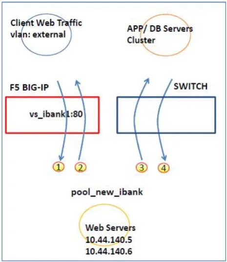
Figure 6. Traffic Flow
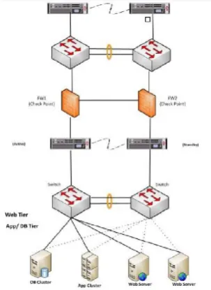
[image:4.595.41.281.476.729.2]Recommended Network Design 2 is Inline Deployment. The explanation is F5 BIG-IP place between firewalls and switches recommended design. Note In inline design App/DB traffic follows to through F5 leads traffic steer may not other team intended which already bypassed need to be compromised carefully in the case only put web severs in inline mode could be the good option.
The design can be shown in Figure 11. Recommended Network Design 3 is Inline Deployment enhanced FWLB (Firewall load balancing). The explanation is BIG-IP sandwich design makes full redundancy of incoming and outgoing load distribution to firewalls. The design can be shown in Figure 12.
[image:5.595.68.532.80.719.2]38696 International Journal of Current Research, Vol. 08, Issue, 09, pp. 38692-38698, September, 2016
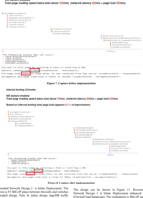
[image:5.595.92.521.432.657.2]Figure 7. Capture before implementation
Figure 9. Network Architecture surround F5
Figure 10. Recommended Design 1
[image:6.595.210.362.577.785.2]Figure 11. Recommended Design 2
Conclusion
The conclusion of implementation load balancing and automatic failover in Bank XYZ are:
Network architecture involved F5 has potentially
significant problem for single point of failure, for the
best practice of design highly recommended
(expect network latency improvement as well)
Outgoing traffic could be load balanced by BIG-IP
leads firewall utilization and resource optimization.
Test environment of Web accelerator gets 30%
percent of page load performance than without it.
However some of contents are still need to be
turned for accurate contents display.
Recommendation of features Java, CSS reordering,
image optimization need to be tuned on UAT for
some period at least 2 weeks and during period also the
content display issue have to be fixed with F5
support.
REFERENCES
https://www.techopedia.com/definition/4197/load-balancing
https://www.techopedia.com/definition/27075/automatic-failover
Ajit, M. M. and Vidya, M. G. 2013. VM Level Load Balancing in Cloud Environment. IEEE.
https://f5.com/glossary/load-balancer