The plane interaction theory of the cleaning vane
with the head of a root crop
V. Bulgakov, I. Holovach, M. Berezovyy
Educational and Research Technical Institute, National Agrarian University of Ukraine,
Kyiv, Ukraine
Abstract: New interaction theory of a flexible cleaning vane with the head surface of root crop in the case when the vane installed on the driving shaft makes a plane motion is proposed. Based on the obtained differential equations of the vane motion some new mathematical dependencies, describing the basic parameters of this interaction are given.
Keywords: flexible cleaning vane; head of root crop; plane motion; differential equation; interaction
The problem of remainders of haulm removal from the heads of root crops after cutting off its basic mass in many design developments, theoretical and experimental researches is considered (Pogorely 1964; Pogorely et al.1983; Ogurechnikov 1977; Yaroshovets 1980; Mishin 1981; Khelemendyk 1996, 2001; Hurchenko 1997; Hurchenko et al. 2000; Bulgakov & Holovach 2002; Pogorely 2001, etc.). In the scientific works, basically, the re-sults of studies of different kinds of root crop heads cleaners of particular constructions are presented: vane, annular, sectorial, drum, etc.
Nevertheless, strict theoretical substantiation of this technological process does not exist, because neither the initial process of the impact of the cleaning element (flexible vane) on the head of root crop nor its further motion over the surface, which cleaning, by the way, is achieved in the space, nor the differential equations of this motion are thor-oughly or exhaustively examined. In Hurchenko
et al.(2000) the differential equations of motion of flexible cleaning vane on the head of root crop in the case, when the vane accomplishes motions in the transverse-horizontal plane, i.e. it is installed on the cleaner with the vertical rotational axis are represented.
OBjectIVes
In this work the new theory of interaction with the root crop head in the field of the cleaning vane,
installed on the driving shaft with the horizontal rotational axis, is examined.
PrOcedure Of reseArcH
Let us build a calculated mathematical model of the process of cleaning vane interaction with the root crop head. For this purpose let’s compose at first equivalent diagram, in which the spherical head of the root crop, located (actually rigidly fixed) in the soil, above which a driving shaft with the horizontal rotational axis moves, on which it is installed the flexible cleaning vanes, which accomplish an im-pact on the head and the subsequent motion over its surface is examined (Figure 1). We consider that the vanes on the shaft, which has a rotational axis
forward motion of the cleaner along the root crops rows by V—–p and the mass of the vane – by m.
Let us examine at first the case, when the plane of the cleaner vanes rotation is located strictly along of the root crops row (this exactly is such case, when the conditional axis of the vane will coincide with the axis of root crop). In this case, the diagram of velocities and power interaction of the vane with the head of root crop will be plane.
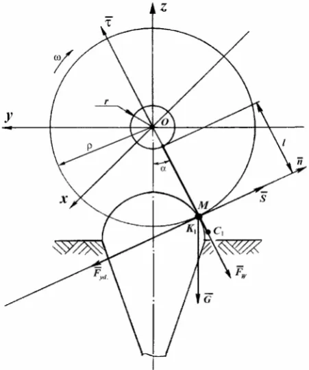
Select a fixed frame xOyz, the beginning of which penetrates the rotational axis of the vane, i.e. the axis
Ox coincides with the horizontal axis of the driving shaft. The axis Oy of this frame is directed along the row of root crops, axis z is vertically upward. See in Figure 1 the diagram of velocities before the impact of the vane on the root crop head and after the impact. Let us again emphasize that in this case the plane of the vane rotation coincides with the plane yOz, and the axis of the shaft O is located along the axis Ox.
During the forward motion of the cleaner along the row of root crops and the rotation of the vane around the axis Ox the impact contact of the vane with the head occurs. Divide the process of cleaning of remainders of haulm from root crop head into two phases:
(1) – the contact phase of the vane with the head of root crop;
(2) – the phase of further motion of the vane on the head of root crop.
OutcOMes Of reseArcH
It is obvious that at the first the impact of the vane on a certain part of the head occurs when the vane encounters with the head of root crop (phase 1). Designate M the point on the vane, which at the moment of impact coincides, with the point K1, the contact of the vane with the head of root crop. We will consider that impact impulse —S will be directed along the normal –n to the head of root crop and
car-ried out through the contact point K1 (Figure 2). At that, velocity V— of the point M on the vane before impact will be equal to
—
V =—VP +V—M (1)
where: —
Vp – the velocity of the forward motion of the cleaner along the row of root crops (the transportation velocity of the vane),
—
VM – circular velocity of point M on the vane during rotation around the axis Ox (relative velocity of point M).
The circular velocity VM of point M will be equal to
VM = ωρ = ω (r + l) (2)
Vector —VM will be directed tangentially toward the circumference of the radius ρ, which is shown in Figure 1.
Since we consider that the impact occurs on the common normal –n to the spherical head of root crop and the vane, and the common normal it is tangent to the circumference of the radius ρ, there-fore vector V—M will be directed along the normal –n
(i.e. actually along the radius of the spherical head of root crop).
Let us separately depict the diagram of the forces, which act on the head of root crop during the impact at the contact point K1 (Figure 2). The force F—yd – the impact force, which appears in the process of the impact and is directed along normal –n to the surface of the head of root crop; —G – the gravitational force of the vane; F—w – the centrifugal inertial force, which appears during the rotation of the vane around the axis Ox (this force is directed along the vane, it contributes to the rectification of the vane along the straight line, i.e., the radius ρ of the gyration of point
M around the axis Ox).
Determine further the absolute velocity U— of point
[image:2.595.65.291.57.325.2]M after the impact, the angle of deflection γ of vec-tor U— from the normal –n and the impact impulse S—.
According to Butenin et al (1985), a change in the momentum of point with mass m at the impact is equal to:
m (U –— V) =— —S (3)
where: —
S— – impact impulse,
U – the velocity of contact point M after impact, —
V – the velocity of contact point M before the impact.
According to the definition, the impact impulse S— is determined with the aid of this expression
(4)
where: –
Fyd – impact force,
τ – the duration of the impact.
Since the duration of impact τ is a very small time interval, the momenta of all the other forces acting on the head of root crops at the moment of impact are in effect equal to zero.
Actually, the power impulse G— will be equal to:
then
Analogously the power impulse F—w will be equal to:
then
Thus, the action of forces G— and F—w with the impact of the vane on the head of root crops may be left unconsidered.
Since when the impact impulse —S is different from zero magnitude, with τ 0, Fyd ∞, since otherwise
—
S 0. This results from the expression (4).
For describing the process of the impact of the vane on the head of root crops let us select a new frame –τK1–n, where the axis –τ is directed tangentially toward the head of root crops at the point K1.
Taking into account that the impact impulse S— is directed along the standard –n, the expression (3) can be represented in this form
mU – m— —V = Sn — (5)
where:
S – the module of the vector of the impact impulse —S.
Write down an equation (5) in the projections on the axis –τ and –n. We will have
or
(6)
Since V =— V—P +V—M, as can be seen from Figure 1, the projections of velocity vectors on the axis –τ and –
n will be equal to:
Vτ = VP sin α Vn = –(Vp cos α + ωρ) (7)
Uτ = U sin γ, Un = U cos γ
where:
α – the angle between axis Oz and the direction of the vane at the moment of impact,
γ – the angle between vectors of velocity U— after impact and standard –n.
³
ΘF˙ddtS
0
Θ G dt G dt G
SG
³
Θ Θ³
0 0
0 lim lim
lim
0 0
0 o o
o SG Θ GΘ GΘ Θ Θ
0 lim lim
lim
0 0
0 o o
o Fw Θ FwΘ Fw Θ Θ Θ
Θ F dt F dt F
S w
Θ Θ
w w
Fw
³
³
0 0
¿ ¾ ½
S mV mU
mV mU
n n
Θ
Θ 0
°¿ ° ¾ ½
S m V U
V U
n n
Θ Θ
[image:3.595.64.290.60.330.2]1 0 Figure 2. Forces, which act at the contact point of the vane
From the first equation of the set (6) we obtain
Uτ = Vτ
then, taking into account (7), we will have
U sin γ= Vp sin α
whence we find the absolute velocity —U of the point
M after the impact
γ α
sin sin
P V
U= (8)
In accordance with the concept of recovery fac-tor ε during the impact (12), it is possible to write down
(9)
Substitute in (9) for U its value, which is deter-mined according to expression (8), we have
γ ρ ω α
α
ε ctg
cos sin
+ =
P P V
V (10)
We find from expression (10)
(11)
then
(12)
For enumerating the module of velocity U after impact we will use the trigonometric identity
γ γ
2 ctg 1
1 sin
+
= (13)
From equation (8), taking into account (13), we obtain
γ α 1 ctg2
sin +
=VP
U (14)
Substitute in the last expression (14) for ctgγ its value according to expression (11). We have
(15)
Thus, the magnitudes of the module of the veloc-ity U of the point M of the vane after impact and the angle of deflection γ of vector U— from normal –n to the surface of the head of the root crops are obtained.
Determine further impact impulse S. Using the determination of the recovery factor with the impact ε, it is possible to write
Un = ε∣Vn∣
or
Un = –εVn (16)
Substitute into the second equation of the set (6) instead Un its expression according to (16), we will obtain
S = –m(1 + ε)Vn
or, by taking into account (7), finally find the impact impulse S
S = m(1 + ε) (VP cos α + ωρ) (17)
After the first phase (encounter of the vane with the head of root crop, or impact of the vane on the head of root crop), the second phase sets in, i.e. the motion of the vane on the head of root crop, dur-ing which the basic process of the beatdur-ing of the remainders from the head occurs. For the analytical description of this process, it is necessary to compile the differential equations of the motion of point K (arbitrary point of the moving vane), the contact of the vane over the surface of the root crop.
It should immediately be noted that the diagram of power interaction at contact point K during the mo-tion of the vane in the surface of root crop will differ from the diagram of power interaction, which occurs during the impact of the vane on the head of root crop (Figure 2), since in this case, actually, another system of forces will act at the indicated point.
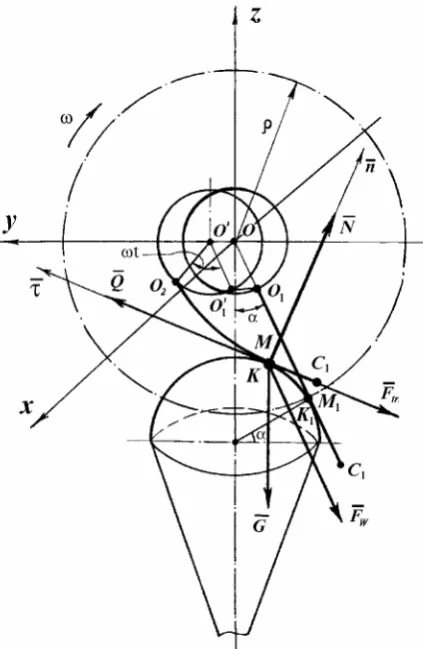
Depict the power interaction of the vane with the head of root crop with the fulfillment of the basic process of the beating of the remainders, i.e. dur-ing the motion of the vane over the surface of root crops (Figure 3). At contact point K the following forces will act:
—
Fw – the centrifugal inertial force, which is directed along the radius OK of gyration of the vane around the axis O;
—
G – the gravitational force of the vane, which is directed vertically downward;
—
N – the normal reaction of interaction of the vane with the head of root crop, directed along the normal –n to the head of root crop, carried out through this position of contact point;
—
Ftr – the frictional force, which appears during the motion of the vane along the head of root crop, directed to the side, opposite to the di-rection of the vector of the absolute velocity of the point M of the vane which coincides with the contact point K ;
΅ V
Ή Ε Ν ΅ V ·
P P
sin cos
ctg
» ¼ º «
¬
ª
΅ V
Ή Ε Ν ΅ V ·
P P
sin cos arcctg
2 22
2 sin ΅ V cos΅ ΝΕ Ή
V
U P P
Ε Ν ΅ V
· U V
U Ή
P n ˔
+ cos
cos =
—
Q – the force of the beating of the remainders of haulm from the surface of root crop, which is directed to the side of the vector of the absolute velocity of the point M of the vane. Find the magnitudes of the indicated forces. For the determination of the centrifugal inertial force F—w
at any contact point K it is necessary to examine the kinematics of the motion of the vane O1C1 on the head of root crop after the impact contact at point
K1. Since the impact occurs for a very small time in-terval, at the moment of the impact of the vane there is actually no displacement over the head of root crop. Therefore for the initial position of the vane on the head of root crop after impact it is possible to count the position of the impact contact K1.
After impact only the absolute velocity U of the vane was changed, which was determined above ac-cording to the expression (15) with the initial veloc-ity of the motion of the vane after impact. Let M1 be the point on the vane, which at the initial moment
t = 0 after impact coincides with the point of the initial contact K1. At this moment the vane O1C1 is still directed along a radius ρ , since the impact of the vane has been considered above as an absolutely constant value.
Examine further the contact of the vane with the head of root crop at point K at any moment of time
t after impact. It is quite obvious that in time t the point O of the rotational axis of the vane with the forward motion of the cleaner will move into the point O’, moreover
OO’ = VPt (18)
Analogously point O1 will move into the point O1’ with the forward motion of the cleaner, moreover
O1O1’ = OO’ (Figure 3).
Nevertheless, in the rotary motion of the vane around the axis O(O’), poin O1(O1’) will turn in time t to the angle ωt (Figure 5). Thus, in the rotary motion, the suspension point of the vane O1(O1’) will describe the arc O1
˘
’O2, which will be equal to:O1
˘
’O2 = ωrt (19)Thus, in the absolute motion, the suspension point
O1 of the vane will be displaced to the value
OO’ + O1
˘
’O2 = VP t + ωrt = (VP + ωr)t (20)Since we consider that the vane is a continuous nonductile rod, as a result of the displacement of the suspension point O1 to the value (VP + ωr)t, any other point of the vane for the time t interval will move also to the same value. Certainly, each point of the vane moves along its absolute trajectory, which can differ in the form from the trajectories of other points of the vane, nevertheless, along its trajectory the point will move into the value (VP + ωr)t.
This is the major portion of the displacement of the points of the vane, which it is caused by the kinematic, geometric and design parameters of a cleaner of this type.
In this case the contact point M of the vane with the head of root crop will move along the vane from one point M1 to the next C1. Since the point
M belongs to the vane, its movement for the time t interval also constitutes (VP + ωr)t.
If it passes M1C1 = l1 distance in time t1, then it is possible to write down
l1 = (VP + ωr)t1 (21)
whence we find the time of the contact of the vane with the head of root crop
r V
l t
P+ω = 1
1 (22)
Now let us trace the kinematics of the motion of the contact point K along the head of root crops. It
[image:5.595.66.278.59.384.2]is obvious that the major portion of the movement of the contact point K occurs due to the forward motion of the cleaner. Because of the forward mo-tion of the cleaner, the vane as if runs foul of the head of root crops, moving on it until the vane slips throughout the entire length due to the rotary motion or if rotational axis O is displaced beyond the boundaries of the arrangement of root crop. Certainly, a certain displacement of point K occurs due to the bending strain of the vane, nevertheless, it is very insignificant.
Therefore, in the first approximation, it is possible to consider that the displacement of the contact point K for the time interval t will be equal to:
KK1 ≈Vpt (23)
This expression will be necessary during the de-termination of the centrifugal inertial force Fw of the point M, which acts on the head of root crops at the contact point K .
From the expressions (22) and (23) it is possible to determine the movement of the vane over the head of root crop in the time of contact t1 in the first ap-proximation. Namely
r V
l V K K
P P +ω
≈ 1
1
2 (24)
It must be noted that the given kinematic de-pendencies sufficiently approximately describe the process of moving the vane on the head of root crop, and the obtained magnitudes of the time t1 of the contact of the vane with the head of root crop and the movement l1 of the vane over the head of root crops are also approximate.
For the more precise study of the motion of the vane on the head of root crop it is necessary to compile the differential equations of the motion of the point M for the head of root crops, since during this study the forces, which cause this motion are considered.
It must be noted that in the formation of the for-ce of the beating Q— the centrifugal inertial force F—w, thrust —P and rotational moment Mob of the vane play the dominant role. Specifically, because of the acti-on of these forces, the pressing of the vane occurs to the head of root crop and the bending strain of the vane. Actually, immediately after the impact, the centrifugal inertial force F—w is directed along the vane and attempts to straighten the vane along the radius ρ . If this force was absent, then under the action of the forward motion of the cleaner and of the rotary motion of the vane around the axis O of the vane at the contact of root crop would simply be
deflected by a certain angle to the side, opposite to the rotary motion, and without any effort it would slip on the head of root crop, without changing its rectilinear form, since the point of its suspension O1
would hinge.
However, under the action of the centrifugal force
—
Fw towards the head of root crop the vane remains directed along the radius ρ, and therefore, as a result of further forward and rotary motion, the vane will slip on the head of root crops, experiencing in this case the specific bending strains, which create the effect of the beating of the remainders of haulm.
The amount of centrifugal inertial force F—w at the initial contact point K1 (point M1) will be equal to:
Fw1 = mω2ρ (25)
where:
m – the mass of the vane.
Determine the centrifugal inertial force F—w of the point M at any contact point K of the vane with the head of root crop. This force will be equal to
Fw = mω2O’K (26)
where:
O’K– distance from the point K to the point O’.
As can be seen from the diagram in Figure 3, the given distance will be approximately equal to
O’K ≈ OK1 – K1K + OO’ (27)
where:
OK1 = ρ
Then, taking into account that OO’ = VPt and,
KK1 ≈ VPt and also expression (27), we obtain:
O’K ≈ ρ (28)
Thus, the centrifugal inertial force F—w at each contact point K remains approximately constant in the magnitude and the direction and it will be equal to
Fw≈ mω2ρ (29)
In this case, we consider the mass of the vane
tension of the vane and is balanced by the reaction in the hinge O1.
The bending strain of the vane appears as a result of the clamp of the vane at the contact point K by the forces of inertia F—w and the weight of the vane G—
under the action of the tractive P— propelling power of the cleaner and the rotational moment of the vane Mob.
The force of the bending strain will be equal to the force of the beating Q—. Since the propelling power P—
of the cleaner and the rotational moment of the vane
Mîb enter into the composition of forces —Q, they are not shown in Figure 3.
The frictional force, as is known, is equal to
Ftr. =fN (30)
where:
f – the coefficient of the friction of the surface of the vane over the surface of root crop,
N – a normal reaction at the contact point K of the vane with the head of the root crop.
Thus, the differential equation of motion of the contact point K on the head of root crop in the vec-tor form will take this form:
ma = – —Fw + —G + N + — F—tr. +Q — (31)
where:
–
a– the absolute acceleration of the motion of the contact point K on the head of root crops,
m – the mass of the vane.
Since in this case the coplanar force system oc-curs, which is located in plane yOz, then differential equation of motion (31) is reduced to the set of two differential equations of the second order of the following form
(32)
where:
Fwy, Gy, Ny, Ftr.y, Qy – the projection of the force vectors — Fw, G,— N,— —Ftr.,Q — on the axis Oy respectively,
Fwz, Gz,Nz,Ftr.z,Qz– the projection of the vectors of the mentioned forces on the axis respectively.
Taking into account the values of the projections of the vectors of the forces, which enter into the set of differential equations (32), and expression (29) and (30), the mentioned set of equations, acquires this form
(33)
where:
cos (y,^N—), cos (z,^N) — – the direction cosines of the force vector —N to the axesOy and Oz
respectively,
cos (·y^,V—), cos (z·^,V—) – the direction cosines of the velocity vector—V of the motion of contact point K on the head of root crop to the axes Oy and Oz respectively,
·
y, ·z – the projection of the velocity vector — V on the coordinate axis Oy and Oz
respectively.
It is known from Vasylenko (1996), that the mentioned direction cosines will be equal to
(34)
where:
f(y,z) =0 – equation of the relation (surface, over which mate-rial point moves),
∆f – module of the gradient of function f(y,z),
V – module of the velocity vector of the point.
Since it was at first accepted that the head of root crop has a spherical form, the sphere, which can be represented by this equation , is the equation of relation
f(x,y,z) = x2 + y2 + z2 – R2 = 0 (35) where:
R – a radius of the spherical head of the root crops.
For the plane yOz x = 0, and therefore the equa-tion of sphere (45) passes into the equaequa-tion of cir-cumference
f(y,z) = y2 + z2 – R2 = 0 (36)
According to Vasylenko (1996), the module of the gradient of function and the module of velocity will be equal to
2 2 z y
V = + (38)
Let us substitute (34) in (33) and will add to the set of differential equations (33) the equation of relation (36), then we obtain the following set of differential equations:
(39)
Calculate partial derivatives and gradient of the functions, which enter into the set of equations (39). We will have:
z z f y y f 2 , 2 = ∂ ∂ = ∂ ∂ (40)
Then, according to (37)
( ) ( )
y z Rf = 2 2+ 2 2 =2
∆ (41)
Substitute expressions (40), (41) in (39). Then the set of differential equations (39) acquires this form
(42)
The set of equations (42) is the set of three equa-tions with three unknown quantities y, z and N. Therefore, it is specific and has unique solution.
Let us exclude from the obtained set of equations (42) the unknown quantities N and z, thus bringing together this set to one differential equation with one unknown function y(t). For this, t should be differentiated two times on the equation of relation (36). If we differentiate this equation one time, then we obtain
2yy + 2z· ·z = 0 (43)
whence we find
yy + z· ·z = 0 (44)
If we differentiate equation (44), then we will have
y·y· + y·2 + z·z· + z·2 = 0 (45)
or
(y·y· + z·z·) + (y·2 + z·2)= 0 (46)
Since y·2 + z·2 = V 2, we will obtain
V 2 = –(y·y· + z·z·) (47)
Let us multiply the first equation of the set (42) by
y, the second one by z and let us accumulate them one by one, then we will obtain
(48)
whence, taking into account the expressions (44) and (47), we will have
–mV 2 = –mω2ρ (y sinα + z cosα) – mgz + RN (49)
From the expression (49) we find the normal reac-tion N. It will be equal to
N = 1 [mω2ρ (y sinα + z cosα) + mgz – mV2] (50)
R
Carry out further conversions. From the expres-sion (44) we obtain
(51) then
(52) or
(53)
Thus, for the value of the square of the velocity of motion V we can obtain this expression
(54)
Substituting the expression (50) into the first equation of the set (52), we obtain
(55) ° ° ° ° ¿ °° ° ° ¾ ½ w w w w 0 ̇ cos ̇ sin 2 2 2 2 2 R z y V z Q V z N f z f f N mg ΅ Ε Ν m z m V y Q V y N f y f f N ΅ Ε Ν m y m ° ° ° ° ¿ ° ° ° ° ¾ ½ 0 cos sin 2 2 2 2 2 R z y V z Q V z N f N R z mg ΅ Ε Ν m z m V y Q V y N f N R y ΅ Ε Ν m y m
yy zzV Q z z y y V N f z y R N mgz ΅ z Ε Ν m ΅ y Ε Ν m z z y y m 2 2 2 2 sin cos
Since z = √ R2 – y2 , taking into account the
expres-sion (54), we will finally have
(56)
Thus, the differential equation of the second order is obtained, in which only one function y is unknown, i.e., is obtained by the differential equa-tion in the so-called normal form, since the higher derivative is expressed as the lowest derivatives and the unknown function.
The unknown force Q, which enters into the equa-tion (56), must be found from the realizaequa-tion condi-tions for the process of the beating of the remainders of haulm from the head of root crop during the necessary bending strain of the vane.
Therefore, to solve this equation it is necessary at the first to find the force Q, or to express it through the unknown quantities.
Since equation (56) is nonlinear, it is possible to solve it only by numerical methods on the personal computer under the assigned initial conditions. Let us find such conditions. The initial velocity of the contact point K1 of the vane with the head of root crops will be the absolute velocity of the point M1
of the vane after impact, since at this moment the point M1 coincides with the point K1. Thus, as can be seen from Figure 1,
·
y0 = Usinγ sinα – Ucosγ cosα (57) Thus, the initial conditions for the differential equation (56) take this form:
with t = 0:
y0 = –Rcosα (58)
·
y0 = Usinγ sinα – Ucosγ cosα
where:
U – determined according to the expression (15), γ – determined according to the expression (12).
The differential equation of the motion of point
K in the projection on the axis zO can be found by analogous conversions, nevertheless, for this there is no need, since, knowing y and ·y, from equation
(36) it is possible to determine z and·z.
cONcLusION
Thus, the differential equation of motion of a flat elastic cleaning vane on a head of a root crop which is in soil motionlessly is received. Thus the cleaning vane installed on a horizontal driving shaft, car-ries out in the beginning impact, and then driving on a spherical head of a root crop. The case when the plane of rotation of a cleaning vane is located strictly lengthways of some root crops, i.e. when the conditional axis of the vane coincides with an axis of a root crop is examined. The received analytical de-pendences can be used at designing new construc-tions of standing root crops heads cleaners.
references
Bulgakov V.M., Holovach I.V. (2002): The theory of clean-ing of heads of root crops by the cleaner with a vertical axis of rotation. (in Ukrainian) In: Proc. KMTI Mechanization of Production Processes of the Fisheries, Industrial and Agrarian Enterprises, 4. Kerch, KMTI: 209–226.
Butenin N.V., Lunts Y.A.L., Merkin D.R. (1985): The Course of Theoretical Mechanics. (in Russian) Vol. 2. Moscow, Nauka.
Hurchenko O.P. (1997): Substantiation of the basic param-eters of the vane cleaner of the beet heads from remainders of haulm. Agricultural machines. (in Ukrainian) In: Proc., Vol. 3, Lutsk, 30–37.
Hurchenko O.P., Orekhivsky V.D., Berezovyy M.H. (2000): Theoretical substantiation of parameters of the vane cleaner of heads of root crops of a beet from haulm. (in Ukrainian) In: Proceedings NAUU Mechanization of Agricultural Production, Vol. VII. NAUU, Kyiv, 279–285. Khelemendyk N.M. (1996): Increase of mechanical and
technological effectiveness of labour-intensive processes in the sugar beet breeding. (in Ukrainian) [Dr. Sci. Tech. Thesis.] Ternopil, TPI.
Khelemendyk N.M. (2001): Guidelines and the Methods of Developing of the Operating Units of Agricultural Ma-chines. (in Ukrainian) Agrarna nauka, Kyiv.
Mishin M.A. (1981): Research and substantiation of end-ef-fectors for additional cleaning heads of a sugar beet roots from remainders of haulm. (in Russian) [Cand. Sci. Tech. Thesis.] VISHOM, Moscow.
Ogurechnikov N.A. (1977): Search, research and substan-tiation of technological process and operating tools for cleaning of the sugar beet roots heads. (in Russian) [Cand. Sci. Tech. Thesis.] TNIIMESH, Minsk.
Pogorely L.V. (1964): Research and development of the technological process of separation of haulm from the sugar beet roots. (in Russian) [Cand. Sci. Tech. Thesis.] USHA, Kyiv.
^
>
@
2 2 2 22 2
2 2
2 2
2 2 2
2
2 2 2
2 2
2 2
2 2 2
1 cos
sin sin
y y y y R
y R y Q
R y
R
y y y y R m y R mg
΅ y R ΅ y Ε Ν m
y y y y R
y R y f R
y ΅ Ε Ν m y m
°¿ ° ¾ ½
u
u ¸ ¸ ¸
¹ ·
¨ ¨ ¨
© §
Pogorely L.V., Tatjanko N.V., Brey V.V. et al. (1983): Beet Harvesters (Design and Calculation). (in Russian) Tekhnyka, Kiev.
Pogorely M.L. (2001): Increase of technological effective-ness of beet harvesters. (in Ukrainian) [Cand. Sci. Tech. Thesis.] NAUU, Kyiv.
Vasylenko P.M. (1996): Introduction into the Agricultural Mechanics. (in Russian) Silgosposvita, Kyiv.
Abstrakt
Bulgakov V., Holovach I., Berezovyy M. (2006): teorie vzájemného působení ometací lopatky s bulvou. Res. Agr. Eng., 52: 87–96.
Návrh teorie vzájemného působení pružné lopatky ometače s povrchem bulvy kořenových plodin v případě, kdy lopatka instalovaná na hnacím hřídeli vykonává rovinný pohyb. Na základě získaných diferenciálních rovnic pohybu lopatky se uvádějí nové matematické závislosti popisující základní parametry zkoumaného vzájemného působení.
Klíčová slova: pružná ometací lopatka; bulva; rovinný pohyb; diferenciální rovnice; vzájemné působení
Corresponding author:
Prof. Volodymyr Bulgakov, Dr.Sci.Tech., National Agrarian University of Ukraine, Educational and Research Tech-nical Institute, Heroiv Oborony Str 15, 03041 Kyiv, Ukraine
tel.: +380 445 278 263, fax: + 380 442 585 397, e-mail: [email protected]
Yaroshovets V.R. (1980): Classification of operating units for removal of haulm from heads of sugar beet roots. (in Russian) In: Reserves for an Increase in Productivity and Quality of the Sugar Beet. Proc. Scient. Conf. VNIS. Kyiv, 241–245.