V/ESDI 4201 Panther ,
High-perfonnance
VMEbus Enhanced SlIlall
Device Interface (ESDI)
Disk Controller
User's Guide
V/ESDI 4201 Panther
High-perfonnance
VMEbus Enhanced Slllall
Device Interface (ESDI)
r
Release Date October, 1988
CAUTION
Specific configurations of the V/ESDI 4201 use rows A & C of the connector on P2 for I/O signals. To avoid possible damage to this board, the backplane, or other system components, verify compatibility with the system before installing this board and applying power.
FOR ASSISTANCE IN USING THE V/ESDI 4201 OR ANY
OTHER INTERPHASE PRODUCT CALL:
INTERPHASE APPLICATIONS ENGINEERING DEPARTMENT
(214) 350-9000
IN THE U.K., CALL:
COPYRIGHT NOTICE
No part of this publication may be stored in a retrieval system, transmitted, or reproduced in any way, including, but not limited to photocopy, photograph, electronic or mechanical, without prior written permission of INTERPHASE CORPORATION.
Information in this user document supersedes any preliminary specifications and/or data sheets that may have been made available. Every effort has been made to supply accurate and complete information. However, Interphase Corporation assumes no responsibility for its use. In addition, Interphase reserves the right to make product improvements without prior notice. Such improvements may include, but are not limited to, command codes and error codes.
NOTE
1. INTRODUCTION TO THE V/ESDI 4201
Overview ... 1-1 BUSpacket Interface ... 1-1 The FIFO Buffer ... ~ ... 1-2 The Asynchronous State Machine ... 1-2 Virtual Buffer Architecture ... 1-3
aro
Latency ... 1-3 Prefetch Caching ... 1-4 V/ESDI 4201 Optional SCSI Port ... 1-4 V/ESDI 4201 Features and Functions ... 1-5 Command Queing . . . .. 1-6 Command ResIX>nse ... 1-7 Command Parsing . . . 1-7 Performance Advantages ... 1-8 Command Grouping ... . . . 1-8 Overlapped Seeks ... 1-8 Command Sorting ... 1-9 Search Cache on Reads ... 1-9 Command Latency ... 1-9 Other Considerations ... 1-9 Utilizations of VMEbus Facilities ... 1-11 VMEbus Structure .. ;... . . . 1-11 Data Transfers ... " ... 1-11 Bus Master ... " , .... 1-11 Bus Slave ... 1-12 Data Transfer Operations ... 1-12 VMEbus Addressing ... 1-12 Short I/O ... 1-13 Arbitration ... 1-14 Priority Interrupts ... 1-15 Interrupt Operation ... 1-152. INSTALLATION OF THE V/ESDI 4201
3. INITIALIZING THE V/ESDI 4201
{)verview ... 0 ••• 0 . 00 ••••• 0 •••••••••.•.•••••••••••••••...•. 3-1 Unit Initialization Block .. 0 0 0 • 0 • 0 0 •• 0.0 o • • 0 ••• 0 •••• 0 0 0 0 o • • • • • • • • • • 3-1 Volume Specification: UIB Bytes 0-3 •••••••••.•••••••••••••••... , . 3-2 Sectors/Track: UIB Byte 4 0000.0. 0 • o • • • • 0 ••••••••••• 0 ••••..••••.• 3-2 Spiral Skew:
urn
Byte5 ...
o. 00 0 0 0 •••• 0 0 ••••••• 0 • 0 ••• 0 • 0 .• 0 •••• 3-3 Bytes Per Sector: UIB Bytes 6 and 7 ... 0 • • • • • 0 • • • • • • • • • • • • • • • 3-3Gap 1 Words: UIB Byte 8 ... o • • • • • • • • • • • 0 • • • • • • • • • • • • • • • • • • • • 3-3
Gap 2 Words: UIB Byte 9 .... 0 • • o • • • • • • • • • • • • • • • • • • • • • • • • • • • • • • • • 3-3 Sector Interleave: UIB Byte A 0 0 •••••••••••••••••• 0 ••••••••••••••• 3-3 Retry Count: UIB Byte B .... 0 ••• 0 • 0 •• o. o ... 0 0 •• 0 •• 0 •••••••• 3-3 Number of Cylinders: UIB Bytes C and Do ... 3-4 Attributes: UIB Byte E ... 0 ••••••••••• 0 ••••• 0 •••• 0 .0 ••••••••••••• 3-4 Second Attributes Set: UIB Byte F 0 ••••••••• 0 0 0 00 0 •••••• 0 •••.• 0 0 • 0 3-5 Status Change Interrupt Level, Register and Vector:
UIB Bytes 10 and 11 0 00 0 ••• 0 •••• 0 ••••••••• 0 ••••• 0 ••••••••.••••.•• 3-7 Extended UIB . 0 0 '0' 0 .00 •••• 0' ••••••• 00. 0 ••••••• 0 •••••••••••••• 0 .3-7 Write Delay: VIB Byte 12 •• 0 ••• 0 ••••••••• 0 0 • 0 ••••••••.••••• 3-8 Number of Spares:
urn
Byte 13 •••• 0 •••••••••••••••••••••••• 3-8 Command Complete Timout (MSB and LSB):VIB Byte 16 and 17 •• 0 0 0 0 •• 0 0 0 •• 0 ••••••• 0 • 0 ••••• 0 0 ••••••••• 3-8 Default VIB 0 • 0 0 •• 0 0 0 ••••• 0 •• 0 0 0 ••• 0 0 0 • 0 0 0 0 • 0 0 0 0 0 ••• 0 •••••••••• 0 • 3-8 Initialization of Disk Media. o • • 0 ... 0 ••• 000 ... 0.0 •• 03-10
Overview ... 4-1 How to Issue a Command ... 4-4 Interrupts ... 4-4 IOPB and I/O Registers ... 4-6 Status Registers ... 4-6 Command/Status Register ... 4-6 Drive Status Register ... 4-10 Enhancing ESDI Disk Performance ... 4-12 Linked IOPBs ... 4-12 Scatter/Gather Operation ... 4-13 Scatter/Gather Lists ... 4-13 Scatter/Gather Guidelines ... 4-15 Scatter/Gather Completion ... 4-15 Overlapped Seeks ... 4-15 Status Change Interrupts ... 4-16
S. INPUT/OUTPUT PARAMETER BLOCK (IOPB)
6. MULTIPLE ACfIVE COMMAND SOFIWARE INTERFACE (MACSI)
Ml\.CSI Overview ... 6-1 Command Queues ... 6-1 Work Queues ... 6-1 Command Response Block ... 6-2 Performance Issues ... ~ ... ~ ... 6-2 Go to MACSI Mode Command ... 6-4 Number of Command Queue Entries ... 6-6 Command Response Block Offset ... 6-6 MACSI Flags ... 6-6 Number of Command Queue Entries ... 6-6 Back to Back Write Count ... 6-6 Round-Robin Count ... 6-6 Go to MACSI Mode Error Conditions ... 6-7 System Interface Detailed Description ... 6-9 Master Control/Status Block (MCSB) ... 6-11 Master Status Register (MSR) ... 6-11 Master Control Register (MCR) ... 6-12 Interrupt on Queue Available Register (IQAR) ... 6-13 Queue Head Pointer ... 6-15 Command Queue ... 6-16 Command Queue Entry (CQE) ... 6-16 Queue Entry Control Register (QECR) ... 6-17 10PB Address ... 6-18 Command Tag ... 6-18 10PB I..ength ... 6M 18
Host Usable Space (HUS) ... 6-18 Command Response Block (CRB) ... 6-19 Command Response Status Word (CRSW) ... 6-20 10PB Type ... 6-21 Command Tag ... 6-22 10PB I..ength ...•... 6-22 Returned IOPB ... 6-22 Device Status Block (DSB) ... 6-23 Tape Status Register ... 6-23 Board Status Bits Register ... 6-25 VMEbus Interrupts ••... 6-26
A. Specifications of the V/ESDI 4201 B. Cable Interfaces
C. Command Codes D. Error Codes
E. "C" Language Data Structure
GLOSSARY OF TERMS
FIGURES
Figure 1-1 Typical Computer System. . . .. . . .. . . .. .. . . .. . .. 1-7
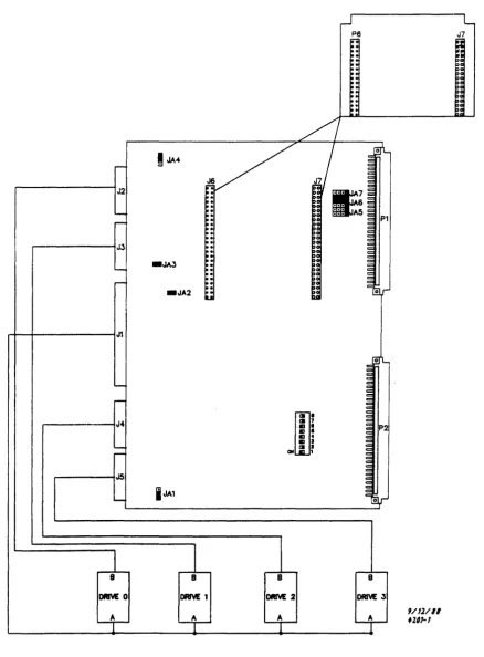
Figure 2-1 Board I...ayout ... 2-2
Figure 2-2 Cable Installation ... 2-3
Figure 2-3 Jumper Configuration ... 0 • 0 •••• 0 0 • 0 0 0 0 • 0 0 •• 0 0 0 0 • 0 0 •••• 0 • 2-6
Figure 3-1 UIB Attribute Byte Eo 0 0 00.0 •••••• 0 • o ••••• 0000000000 •• 0 0 00000 3-4
Figure 3-2 UIB Second Attribute Byte F 0 0 • 0 0 0 0 0 0 0 0 • 0 0 • 0 0 0 0 ••.• 0 ••••• 0 0 0 0 3-6
Figure 3-3 Typical Disk Unit ... 3-10
Figure 3-4 Sample Formatted Sector ... 0 •••• 0 •••• 0 0 •• 00 3-11
Figure 3-5 Sector Slip. 0 0 0 0 .0 00.0 000 •• 0 0 0 0 0 0 0 •••• 00 00. 0 ••••••••••••••• 3-15
Figure 4-1 V/EDSI 4201 Standard Short I/O Format 00000000000 •• 000 ••• 0 0 00 4-2
Figure 4-2 V/EDSI 4201 w/SCSI Port I/O Memory Format 000 0000 0 0 0 0 • 0 o. 00 4-3
Figure 4-3 Operations flowchart ... 0 0 0 0 0 0 0 0 0 0 • 0 0 0 0 0 0 0 0 0 0 0 0 ••••••••••• 4-5
Figure 4-4 Command Status Register Format o. 0 0 0 0 0 0 0 • 0 0 0 0 0 0 0 0 0 0 0 0 0 0 ••••• 4-7
Figure 4-5 Drive Status Register ... 0 . . . 0 . . . 4-10
Figure 5-1 Command Options Byte Format ... 0 ... 5-3
Figure 6-1 MACSI Control Structures Block Diagram ... 0 ••••• 00 •• 000 •• 6-3
Figure 6-2 MACSI aD Block ... 0 0 0 ••••• 0 0 0 • 0 ••• 0 •• 0 •• 0 0 0 0 0 0 0 0 6-5
Figure 6-3 Exampe 4201 MACSI System Interface Memory Map o. 0 • 0 0 •• 0 • 6-10
Figure 6-4 Master Control/Status Block (MCSB) .0.000 •• 00 ••••••• 000 •• 0 • 0 6-11
Figure 6-5 Master Status Register (MSR) 0.00000.000000 •• 000 •• 0000000 •• 0 6-11
Figure 6-6 Master Control Register (MCR) .... 0 0 • 0 0 0 0 • 0 •• 0 ••• 0 •••• 0 ••••• 6-12
Figure 6-7 Interrupt on Queue Available Register (lOAR) 0 ••••• 0 •••••••••• 6-14
Figure 6-8 Queue Head Pointer/Queue Head Pointer in Use 0 0 ••••• 0 0 ••• 0 • 0 0 6-15
Figure 6-12 Command Response Status Word (CRSW) ... 6-20
Figure 6-13 IOPB TyfJe ... . . .. 6-21
Figure 6-14 Format of the TafJe Status Register ... 6-24
Table 1~1
Table 2-1
Table 2-2
Table 3-1
Table 3-2
Table 3-3
Table 4-1
Table 4-2
Table 5-1
Table 5-2
Table 5-3
TablG 5-4
Table 5-5
Table 5-6
Table 5-7
Table 6-1
TABLES
Procluct Variations ... 1-6
P2 Connector Scheme ... 2-4
Base Address Switch Settings ... 2-5
lJIB Format ... 3-2
Extended lJIB . . . 3-7
])efault UIB ... 3-9
A1-A4 Command Codes ... 4-14
AS-A6 Command Codes ... 4-14
IOPB Format ... 5-1
V/ESDI 4201 Disk Control Commands ... 5-2
Command Status Codes ... 5-5
Error Codes . . . 5-7
IOPB Words 2-13 ... 5-8
IOPB (Word 7) Memory Type Codes ... 5-9
linked IOPB (Word 12) Memory Type Codes ... 5-11
r
WARNING
1
INTRODlJCTION
Catastrophic DAMAGE can result if improper connections are made. Therefore, those planning to connect power sources to the VMEbus for the purpose of feeding the user defmed pins of P2 (Rows A and C) should FIRST CHECK to ensure that all boards installed are compatible with those connections.
The Panther offers two modes of operation: Non-MACSI, which is explained in this user's guide primarily for backwards compatibility with previous versions of Interphase drivers and products; and MACSI, thecommand queingmode of operation, which offers the best possible performance from the board.
N on-MACSI operation is explained in Chapter 4. Input/Output Parameter Blocks are explained in Chapter 5 and MACSI operation is explained in Chapter 6.
Overview
The V/ESDI 4201 Panther is an extremely fast, intelligent, Enha.nced Small Device Interface (ESDI) controller/formatter used to interfa(.'c VMEbus-based systems to ESDI compatible disk drives. The V/ESDI 4201 call support any combination of four ESDI drives, hard or soft sectored.
Its intelligence is based on a M68000 16/32 bit microprocessor running with no wait states. The real key to the V/ESDI 4201, however, is the proprietary BUSpacket InterfaceSM and the Multiple Active Command Software Interface (MACSI).
The V /ESDI 4201 achieves a throughput far superior to that of any competitive controller by sending preformatted data packets across the VMFbus at rates up to 30 megabytes per second.
BUSpacket Interrace
V/ESDI 4201 Panther
With a bus data rate up to 30 megabytes/second the V/ESDI 4201 comes dose to fully utilizing the 40 megabytes/second theoretical bandwidth of the VMEbus. This high bus data rate means that the V/ESDI 4201 spends less time on the bus than other controllers, conserving bus bandwidth for oth'!r processes.
There are two keys to the speed of the BUSpacket Interface: a deep FIFO buffer and a delay-line-based asynchronous state machine.
The FIFO Buffer
The deep FIFO buffer of the BUSpacket Interface is a very high speed 512-byte FIFO that can write a BUSpacket to (or read a BUSpacket from) the Panther's 128 Kbyte buffer with a fast block transfer. The FIFO itself is very fast so that once it is connected to the VMEbus, the DMA can proceed at 30 megabytes/second Thus, the speed of the controller (on the VMEbus) is totally decoupled from the speed of the 128K RAM buffer and the peripheral device attached to the controller.
During a read from the disk, for example, the FIFO buffer is filled with a packet of data from the buffer memory prior to the controller acquiring the bus. once on the bus, the packets are burst across the bus (in DMA mode). When the transfer is complete the bus is immediately released for other uses. This is continued until all of the information requested in the read or write command has been transferred to/from system memory. During a DMA operation to/from the BUSpacket FIFO no other functions (such as caching) are impeded.
The Asynchronous State Machine
The V/ESDI 4201 uses an asynchronous state machine (in lieu of a traditional variety) in the BUSpacket Interface to control the DMA transfer of data to/from the VMEhus.
Synchronous state machines, which are typically used to control the entire DMA operation, must first synchronize the inherently asynchronous VMEbus control signals to avoid metastable states. This synchronization cycle will, on the average, delay the signal by one and a half periods of the synchronizing clock. This means that a synchronous state machine running at 20 MHz, for example, will delay any control signal off of the bus by an average of 75
nanoseconds before it uses it as an input to the state machine. Such a delay is an unacceptable portion of the 100 nanosecond cycle time required to achieve a 40 megabyte/second data rate on the VMEbus.
In contrast, the high-speed DMA transfer of the BUSpacket Interface on the V/ESDI 4201 is controlled by an asynchronous state machine that runs off of a tapped delay line. A tapped delay-line-based state machine avoids
Virtual Buffer Architecture
smZero Latency
The M68000, running under a proprietary, multitasking real time firmware operating system, is used to regulate controller activity, such a~) sequencing commands and setting up data transfer operations. Its most important function, however, is to manage the pool of virtual buffers that is composed from the V/ESDI 4201's 128 Kbytes of RAM.
At any given time individual buffers may be allocated to either the disk, the VMEbus, or the cache. The 68000 microprocessor will dynamically allocate and deallocate buffers as they are requested or released by the VMEbus or the disk. During a disk read, for example, the disk read task brings data into a free buffer. Simultaneously, as soon as any sector of interest has been
captured, the bus write task begins moving data into system memory; thus, the sector buffer is freed. If the VMEbus cannot keep up with the drive, the buffers will hold the data until the bus is ready. The buffer thus prevents either overrun or underrun of data. The V/ESDI 4201 is able to apply many high-performance techniques which can reduce or eliminate disk rotational latencies. These methods include zero latency reads and writes, and intelligent caching.
A traditional controller, upon receiving a multisector request from the operating system, will wait until it encounters the first required sector before beginning to read and transfer the data. Thus, it will incur an average rotational latency equivalent to one half of one track. If the request is for a full track of data, even with a 1:1 interleave factor, the traditional controller will take an average of one-and-half revolutions to complete the transfer.
The V/ESDI 4201 begins reading data as soon as the heads land on the track (i.e., zero rotational latency) and begins transferring data as soon as it encounters a sector of interest; it does not wait to rotate around to the beginning of the requested string. In this manner, the V/ESDI 4201 will never require more than a single revolution to transfer an entire track of data.
Zero latency writes are accomplished using the same principle. This
V!ESDI 4201 Panther
Prefetch Caching
To further reduce latency, the V/ESDI 4201 uses an intelligent caching scheme (prefetch caching) to anticipate which data sectors will be reque.sted next. When the V!ESDI 4201 has completed a read operation and has transferred the requested data, it will continue to read sectors into the cache until all available buffers have been filled, or until it receives a command from the host requesting a head movement. And with the large 128 Kbyte RAM buffer, the V!ESDI 4201 can even cache across track boundaries. Thus, if subsequent requests from the operating system are for sectors logically contiguous with the previous sectors, these requests can be satisfied directly from the cache without having to access the disk. In disk intensive
applications this can greatly improve overall system throughput.
This form of caching is particularly useful for UNIX and UNIX-like operating systems. Tests have shown improvements in disk operation averaging greater than 40 percent over operation with 1:1 interleave only. Caching shows the greatest improvement when disk activity is characterized by a large number of short transactions.
V /ESDI 4201 Optional SCSI Port
The V/ESDI 4201 can be equipped with an optional SCSI port to provide convenient archiving and tape backup capabilities. This addition allows the V/ESDI 4201 to control not only four ESDI disk drives, but at the sa:ne time, to control up to seven SCSI devices.
When a V/ESDI 4201 is equipped with a SCSI port, the Short I/O memory format is modified to accomodate the addtional command set, status registers, et cetera, that are required for SCSI device operations. In addition, 16 Kbytes of the 128 Kbytes of on-board RAM are used as a buffer between the tape devices and system memory. This buffer enables the V /ESDI 4201 to operate concurrent bus and tape operations. So while the tape is processing a
transaction, the V/ESDI 4201 is reading/writing to/from the buffer to prepare for the next tape operation. This aids in providing tape streaming on a command basis.
V /ESDI4201 Features And Functions
The V/ESDI 4201 provides many options which are either under software control or are mechanically selectable by switch or jumper. For example, sector sizes are programmable varying from 128 bytes to 2048 bytes. The most important features and functions of the V/ESDI 4201 are outlined as follow:
• The BUSpacket Interface boosts DMA throughput in excess of 30 megabytes per second.
• The V/ESDI 4201 is controlled using a simple macro-level software interface.
• The on-board M68000 16/32 bit microprocessor relieves the system CPUs of disk handling tasks.
• Optional SCSI port to control up to seven SCSI devices.
• The V/ESDI 4201 can control up to four ESDI disk drives and seven SCSI devices concurrently.
• The V /ESDI 4201 supports 8-, 16-, or 32-bit wide data transfers, and provides 16-, 24-, or 32-bit addressing capability.
• 128 Kbytes of memory is provided; most of which is treated as a pool of virtual buffers.
• The V/ESDI 4201 supports disk data rates up to 24 ~Ib/s with a 1:1 interleave factor.
• Virtual Buffer Architecture reduces or eliminates data transfer delays caused by disk rotational latency and data overrunlunderrun.
• A prefetch caching scheme with dynamic buffer allocation and deallocation is provided Caching algorithms are optimized for UNIX, RMX/86 and similar operating systems.
• Automatic error correction is provided using a 32-bit or 48-bit error correction code (ECe).
• The V/ESDI 4201 can control four ESDI drives (hard or soft sectored).
• Self-diagnostics are performed after each hardware power-up and each software reset.
• Scatter/Gather comands allow the user to place contiguous disk data in noncontiguous areas of system memory or vice versa.
VfE:SDI 4201 Panther
• Overlapped and implied seeks are supported.
• Seven software programmable interrupt levels are provided.
• Bus priority is jumper selectable from zero to three.
• Defective media replacement on a sector or track basis is provided when formatting the disk.
• The disk can be addressed by either physical or logical sectors.
• Zero latency reads and writes insure maximum throughput.
• An interrupt on drive status change is a programmable option for such applications as overlapped seeks.
Coptmand Queuing
In a typical computer (Figure. 1-1) there is a host CPU, some system memory, and a peripheral controller. The host issues commands to the peripheral controller which in tum moves data from the peripheral into (or out of) system memory. The host begins an operation by issuing a command to the controller. If there is no command queue, the controller is idling until the "GO" bit is set in the command. Once the" GO" bit is set, the controller can "decode" the command and start the peripheral in operation. When the controller/peripheral pair finishes the operation (which will typically involve some data movement) the controller issues a command complete interrupt to the host. The host, after servicing the interrupt, starts the cycle over by issuing another command to the controller.
This scenario, with little modification, has been used by controller
manufacturers for years. But as computer manufacturers begin pushing for better and better performance, the problems inherent in this scheme begin to seriously limit performance.
Command Response
In the typical system described above, it may be many microseconds before the" GO" bit in the next command can be set after the host receives the command complete interrupt from the previous command. The sequence is: the controller asserts the command complete interrupt, the host responds by doing a context switch, servicing the interrupt, loading the next command into the controller and setting the" GO" bit. While all of this is going on the controller and peripheral are idle. The controller cannot start processing a command until the" GO" bit of the command has been set.
With a command queue inside the controller the host can load a command into the controller and set the "GO" bit while the controller and peripheral are still processing the previous command. Thus all of the command response time is overlapped with actual peripheral activity. This not only improves performance of the controller/peripheral pair but it also removes time pressure from the operating system so that interrupt response times and context switch times are no longer in the" critical path" of controller
operation. This may allow the system to operate the controller at a lower priority without noticeable degradation of peripheral performance.
INDUSTRY STANDARD BUS
(YME or Multibus)
FtgUre 1-1. Typical Computer System
Command Parsinl
V/ESDI 4201 Panther
A controller without a command queue cannot parse the command until the "GO" bit is set either. But with a command queue, the" GO" bit is set long before the command complete interrupt of the previous command is issued. Thus commands can be parsed while previous commands are being executed. This overlaps command parsing with peripheral operation.
Performance Advantages
In addition to the performance advantages gained by overlapping certain controller and host activity with peripheral activity, as described above, an efficient command queuing scheme can improve system performance by optimizing the manner in which the peripherals themselves are controlled This is true of disk operations in particular, because they are subject to mechanical rotational and head movement delays. Thus improved operation can often be achieved by modifying the "way" in which commands are passed from the controller to the disk.
There are five generalized techniques that can be applied:
• Command Grouping • Overlapped Seeks • Command Sorting • Search Cache on Reads • Command Latency
Command Grouplnl
Command Grouping is a scheme whereby the controller searches the
command queue for commands that can be "grouped" into a single command before issuing the single, concatenated command to the disk. Thus only a single command is issued to the peripheral. Upon completion of this one "macro" command, the controller reports command completion of each of the individual, original commands.
Overlapped Seeks
Once a controller has issued a command to a disk, if there is a seek implied in the command, there will be some seek delay before the head is on cylinder and the disk is capable of transferring data. By issuing seek commands to all of the disks at once these seek times are overlapped so that only one of the seek delays is actually incurred, the others are overlapped with data movement and other activity.
Command Sorting
Disk seek times can also be minimized if the controller sorts the commands beforehand so that the disk is always seeking a nearby cylinder. To ensure that seeks to" outside" cylinders do get issued, the typical algorithm will not allow the head travel to "turn around" until it gets to an extreme. Because this is similar to the method used by elevators in deciding which floor to stop at next, this scheme is called an "elevator sort" algorithm.
Command queuing facilitates this type of command sorting because the controller can easily sort through all of the command in the queue and then issue them to the disk in a prescribed order.
Search Cache on Reads
Disk seek times and rotational delays can be eliminated entirely from read commands if the controller can use data that has already been read into the onboard cache. If the controller finds that the read command is requesting data that is already in the cache, then the command can be satisfied immediately without any waiting. This will work only in RAM-based caching controllers. FIFO based controllers have obvious problems implementing any type of useful cache search on reads.
Command Latency
Not all command queue schemes are the same, and even if the controller has a command queue, there may be differences. For example, another key
parameter that affects overall system operation is command queue latency. This is a measure of the minimum time required (for the host to wait) between issuing commands to the queue. In general this time will be O\i erlapped with
peripheral operation, but it still slows the host down if it must wait a long time before it can issue the next command to the controller.
Ideally the controller can accept commands as fast as the host can normally write to memory. Anything less than this slows the host down.
Other Considerations
In addition to these performance advantages, there are other considerations that affect how useful a command queuing scheme is in a given situation.
In general there should be some mechanism to tailor the queue depth to the application. Longer queues require more manipUlation by the controller and are thus slower but a queue that is too short for the application may not offer significant advantage over a simpler nonqueuing scheme.
V (ESDI 4201 Panther
Utilization Of VMEbus Facilities
The evolution of control applications from 8- and 16-bit buses has progressed up to the development of the VMEbus. The VMEbus is the first bus structure to support a true 32-bit processor. It is comprised of separate 32-bit data and address lines that not only support 32-bit transactions, but also the traditional 8- and 16-bit transactions as well. This makes the VMEbus particularly appropriate for stand-alone or remote process controller applications. In addition, the VMEbus provides the flexibility for expansion within the microcomputer environment. Given all of these advantages, the V/ESDI 4201 is able to exploit the potential of the VMEbus and provide performance necessary in today's systems.
VMEbus Structure
Data Transfers
There are three basic signals which determine the operation of the VMEbus: the Bus Request signal (for getting on the bus), the Bus Grant signal (for allocating the bus for use), and 32 bits of addressing. The addressing is supplemented with six address modifier bits which are used to partition memory spaces. The address modifiers are used to expand memory space by breaking it up into functional blocks.
The VMEbus has seven prioritized interrupts for fully vectored operation. This means that during an interrupt cycle, an interrupt vector provides the CPU with a unique value that describes the interrupt. In nonvectored systems, the CPU must search registers for the cause of the interrupt. The advantage of the vectored interrupt, therefore, is to greatly decrease the ,un~l')unt of time the CPU must spend servicing interrupts.
All VMEbus data transfers are performed over the Data Transfer Bus (DTB). The DTB is 32 bits wide and is only used for data transfers. The VMEbus supports data transfers of eight, 16, or 32 bits. All data transfers take place between a bus master and a bus slave. The VMEbus supports multiple bus masters which provide the capability of moving large blocks of data without CPU intervention; thus, the CPU is not tied up for long periods of time during data transfers.
The V/ESDI 4201 uses the DTB to transfer, commands, status and data between the host system, disk drive, and itself. The V/ESDI 4201 supports 8-, 16-, and 32-bit data transfers.
Bus Master
V/ESDI 4201 Panther
Bus Slave
A bus slave is a device that responds to the DTB master during data transft:rs. When commands are issued to the V/ESDI 4201, or status is read from the board, the V/FSDI 4201 is acting as a slave device.
Data Transfer Operations
During a data transfer cycle several things must happen. First, a bus master must request and be granted the bus. The master then puts the address of the slave to which the data will be transferred on the bus, and if it is a write operation, the data is also put on the bus. Since the VMEbus is completely asynchronous, the master must know when the address is valid and if the slave has either received the data or is ready for more data.
Once the address is valid, the master asserts an Address Strobe signal. Then, the master commands the data on the DTB bus with the Data Strobes. That tells the slave that the address is valid and the data is directed at that particular slave. Once the slave has received the data (write operation) or placed the data on the bus (read operation), the slave tells the master that the transfer is complete. To do this, the slave asserts a signal called Data
Transfer Acknowledge (DTACK).
There are no restrictions on the VMEbus as to how long data transfers can be. The only real restriction is that the address strobe must precede the data strobe.
To start a command, a bus master (typically a CPU) will issue command~ to the V/ESDI 4201 which is acting as a bus slave. After the V/ESDI 4201. has received the command and responded to it, it will then request the V~tEhus,
and when the bus is granted, the V/FSDI 4201 will transfer the data as a bus master.
VMEbus Addressing
The memory space accessible to the V/ESDI 4201 and the host CPU contains several subdivisions. Each subdivision requir::!s a specific type of addressing. This partitioning of the memory space allows more efficient access and utilization of the memory. The addressing options include:
• Short Addressing (16-bit)
• StandardAddressing(24-bit)
The type of addressing is specified using a 6-bit address modifier code that also indicates the nature of the access. For example, address modifiers are commonly used to specify supervisory (restricted) memory access, and user (nonprivileged) memory access. The V/ESDI 4201 supports 16-~ 24-, and 32-bit addressing as well as all address modifiers (as a bus master).
Short I/O
The V/ESDI 4201 requires that all data transfers of control information, command parameters, and status that occur with the host CPU acting as the bus master must be done through the short address space using either address modifiers 29 (user) or 2D (supervisor). This short address space is commonly referred to as Short I/O space. (A 512-byte block of this address space resides in the V/ESDI 4201 on-board RAM.)
The Short I/O is the window through which the host can send commands and parameters, and can review controller status and error codes. The reason that it is called Short I/O space is because any time a board sees a transaction with an address modifier of 29 or 2D in the address strobe, it only looks at the first (lower) 16 address lines even though the VMEbus supports the full 32 address lines. The upper 16 address lines in Short I/O are ignored.
By looking only at the lower 16 address lines, less hardware is needed and less time is spent decoding lines that are not necessary for functions such as reading command registers and status registers. The obvious result is improved performance and reduced cost.
The base address of this block of memory is set by the on-board DIP switches (see section 5).
The V/ESDI 4201 provides Short I/O space on-board as an add.ed feature for improved performance. The 512 bytes of Short I/O provided can
accommodate several commands at once. This proves advantageous to system performance by eliminating the need to DMA every command across the bus. So not only is system performance improved, but bus bandwidth is also conselVed
NOTE
Short I/O space limitations dictate that all accesses be either 8 or 16 bits. Therefore, if the CPU card generates a 32-bit data path and you are using the C programming language, then it is necessary to cast the 32-bit 10PB
V/ESDI 4201 Panther
Arbitration
At some point, either on its own or when it receives a command, every bus master device needs to get on the VMEbus and must request access. Thi~
process of requesting and granting the bus is referred to as bus arbitration.
The VMEbus provides four levels of bus request (0-3) to provide prioritized requests. In addition, bus priority is provided by position of the board in the card cage. The closer the board is to slot one (system controller), the higher priority it is given.
The V/ESDI 4201 bus request priority is selectable via on-board jumpers. The factory setting is bus priority 3.
This system of prioritizing means that if two devices with the same priority simultaneously request the bus, the one closest to the system controller is granted bus access first. However, before any bus grant can be issued, the bus must first be cleared (Le., the current bus master must release the Bus Busy signal).
A VMEbus system may utilize one of three different schemes of bus arbitration based on the two methods of prioritizing bus requests. The first method is called single level arbitration. In this scheme, every device on the bus is assigned the same priority level (e.g., level 3), and the bus requests are prioritized by slot only. This scheme is most useful in low-cost systems where the system controller is on the CPU board. In addition, it takes fewer gates to implement and is less expensive than the other two methods of arbitration. However, the remaining two options offer higher performance than single level arbitration.
The second type is called priority arbitration. Priority arbitration utilizes a signal called Bus Clear. When the system controller sees a request from a higher priority than the one already on the bus, the system controller drives the Bus Clear signal which is a recommendation to the bus master to get off of the bus. When the V/ESDI 4201 receives a bus clear, it will get off of the bus within two bus cycles. This provides better system performance by allowing the V/ESDI 4201 to be run at a low priority level and still not worry about it "hogging" the bus. Finally, the third type of arbitration is called round robin. With this type, there is no fixed priority based on level (Le., three is not always the highest priority). Instead, priority is determined in a cyclical fashion. In other words, if a priority three is on the bus, the next bus grant will be given to priority two (even if another priority three is present), the next will be given to a priority one and the next to a zero and then back to three. It is useful in a system that is using many similar devices. For
example, if four disk controllers are on the backplane and all need equal access to the bus, the need for" position" priority is eliminated In this scheme, each board will have equal access regardless of board position.
Priority
Inte~·ruptsInterrupts are a convenient way for a bus master to tell the CPU that it needs to communicate with another device across the bus. The VMEbus supports seven levels of interrupts with seven being the highest and one being the lowest. The interrupt operation is very similar to the bus grant operation, except the signals involved are the interrupt request from the board and the Interrupt Acknow ledge
(lACK) signal from the system controller. Each V/ESDI 4201 command can be programmed with anyone of the seven interrupt levels.
As in arbitration, interrupts are also prioritized by slot position. Therefore, if multiple boards request interrupts, the system controller drives the lACK signal and it is passed along serially by each board in the system until the interrupting board reads it.
Interrupt Operation
After reading a file, a disk controller may want to tell the CPU that it (the CPU) may now use that data. The disk controller gives up the bus and generates the interrupt request on the specified interrupt level. At some point, when the bus is clear, the system controller passes down the lACK signal. When the board that generated the interrupt reads the signal, it responds by issuing an interrupt vector (if enabled). An interrupt vector describes the interrupt to the system controller. When the interrupt vector is valid on the bus, the CPU is in master mode, and the interrupl.~ug device will respond with a data acknowledge signal. This tells the system controller it has the vector for the CPU. The V/ESDI 4201 supports unique error codes and vectors for several different types of operation. In addition, a different vector can be used to indicate normal completion or completion with error. This can significantly reduce system overhead by instantly identifying the status of each command as it is completed. The V/ESDI 4201 has a separate status change interrupt and vector to facilitate interrupt processing during overlapped seek operations. Because a unique vector can be used, the system can immediately identify the source of the interrupt with a minimum of processing.
V/ESDI 4201 Panther
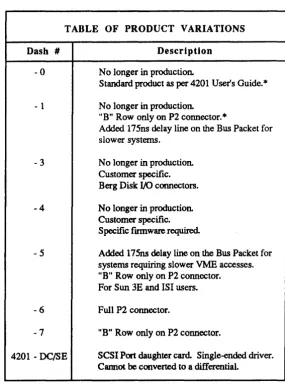
The following table summarizes specific functionality for each of the V/ESDI 4201 boards. For details, please contact Interphase Customer Service.
Table 1-1. Product Variations
TABLE OF PRODUCT VARIATIONS
Dash # -0
- 1
-3
-4
-5
-6
-7
4201 - DC/SE
Description
No longer in production.
Standard product as per 4201 User's Guide.*
No longer in production.
"B" Row only on P2 connector.
*
Added 175ns delay line on the Bus Packet for slower systems.
No longer in production. Customer specific. Berg Disk I/O connectors. No longer in production. Customer specific. Specific fmnware required.
Added 175ns delay line on the Bus Packet for systems requiring slower VME accesses. "B" Row only on P2 connector. For Sun 3E and lSI users.
Full P2 connector.
"B" Row only on P2 connector.
SCSI Port daughter card. Single-ended driver. Cannot be converted to a differential.
[image:28.614.185.470.164.551.2]2
INST ALLA TION OF
THE V /ESDI 4201
Cabling Options
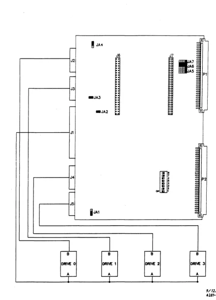
The ESDI drive cables connect to the V/ESDI 4201 through vertically mounted headers (J1-J5) on the V/ESDI 4201 card.
J1 is a 34-pin connector for the ESDI " A" cable. J2-J5 are 20-pin connectors for" B" cable connection of up to four ESDI drives. J2 is the header for drive zero and J3 is the header for drive one, J4 is the header for drive two, and J5 is the header for drive three. Connector pinouts for both the" A" cable and
"B" cables are shown in Appendix B of the user's guide.
If connectors J2-J5 are used to connect the ESDI drives, the cables may be routed through the front of the VMEbus card cage.
For information concerning the installation of the optional V/ESDI 4201 SCSI port, refer to the supplemental user's guide: UG-0780-000-XXX. Details of SCSI connectors, installation procedures and other installation considerations are provided.
V!ESDI 4201 Panther
J:.6
J7::
..
::
::
::
::
,.
~: ~:/ I
!
JA4r:/
J/
ofL~
,.-J2
Ir
~: ... 6
10-' - ~; ::: AS
~ ~: P1
Io!
JJ ~! to-Joo. ~
~
-JA3 ~: ~
..-. ~! ~
to-~ ~: ~
~: c or
_JA2 IIu
J1
'0'1-c: :J
~
' - ~ ~
c
-
im'
J4 III 7
P2
..
.
..
.
..
.
. . 3
-
III J,... aN ,
J5
~
i
JA1 ~l,r1
B B B B
DAM 0 DAM: 1 DAM 2 DRM 3
9/12/11
+
A A+
fll1-1 [image:30.615.102.540.72.665.2]~
!
JA4~
J2
:
:
:
-
:
~:
~J3 ~
~
-JA3
:
--
:
-
:
_JA2
:
LI
J1
----I
~J~
--:'
-J5
----
i
JA18 8
DRIVE 0 DRIVE 1
[image:31.612.115.555.82.692.2]A A
Figure 2-2. Cable Installation
J7
~.
til 7m'iS ., 4
I:J • I:J 3
m 2
OH 1
8
DRIVE 2
A
c:~
1f7
... A6 ~::: A5:;
~ P1 ~ ~ ~ ~ ~ ~ ~ =~,..-~L ~ ~ ~ ~ :;= ~ ~
V /ESD I 4201 Panther
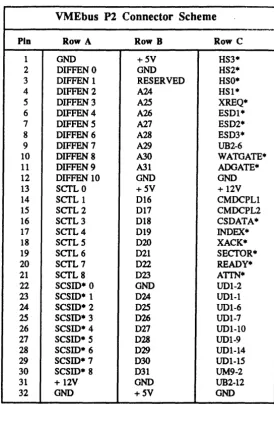
Table 2-1. P2 Connector Scheme
VMEbus P2 Connector Scheme
Pin Row A Row B Row C
1 OND +5V HS3· 2 DIFFENO OND HS2· 3 DIFFEN 1 RESERVED HSO· 4 DIFFEN2 A24 HSl· 5 DIFFEN3 A25 XREQ·
6 DIFFEN4 A26 ESDI· 7 DIFFEN 5 A27 ESD2· 8 DIFFEN 6 A28 ESD3· 9 DIFFEN7 A29 UB2-6 10 DIFFEN8 A30 WATGATE· 11 DIFFEN9 A31 AOOATE· 12 DIFFENI0 OND OND
13 SCTLO +5V + 12V 14 SCTL 1 D16 CMDCPLI 15 SCTL2 D17 CMDCPL2 16 SCTL3 D18 CSDATA· 17 SCTL4 D19 INDEX·
18 SCTL5 D20 XACK· 19 SCTL6 D21 SECTOR· 20 SCTL7 D22 READY·
21 SCTL8 D23 ATrN·
22
scsm·
0 OND UDI-223
scsm·
1 D24 UDl-l24
scsm·
2 D25 UDI-6I
25
scsm·
3 D26 UDI-726
scsm·
4 027 UDI-1027
scsm·
5 D28 UDI-928
scsm·
6 D29 UDI-1429
scsm·
7 D30 UDI-1530
scsm·
8 D31 UM9-231 + 12V OND UB2-12 32 OND +5V OND
Option Switch Settings
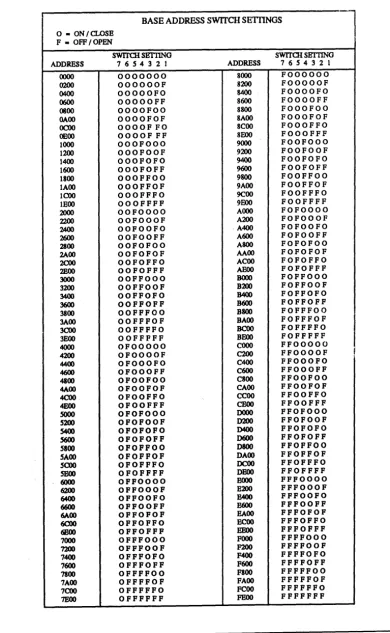
The V/ESDI 4201 has a switch block (Sl) that contains eight switches (numbered 1-8). (see Figure 2-1).
Switches one through seven correspond to VMEbus address lines A9-A15
respectively. An OFF switch has a value of '1' and an ON switch has a value of '0' , which are used to select the base address of the controller. Table 2~2
represents all possible base address and switch settings for the controller.
Table 2-2. Base Address Switch Settings
BASEADDRESSS~CHSETTINGS
l
o - ON /CLOSE F - OFF/OPEN
SWITCH SETTING SWITCH SBTI1NG ADDRESS 76S432] ADDRESS 7 6 S 4 3 2 1
0000 0000000 8000 FOOOOOO
0200 OOOOOOF 8200 FOOOOOF
0400 OOOOOFO 8400 FOOOOFO
0600 OOOOOFF 8600 FOOOOFF 0800 OOOOFOO 8800 FOOOFOO GAOO OOOOFOF 8AOO FOOOFOF
OCOO OOOOFFO 8COO FOOOFFO
OEOO OOOOFFF 8EOO FOOOFFF 1000 OOOFOOO 9000 FOOFOOO
1200 OOOFOOF 9200 FOOFOOF 1400 OOOFOFO 9400 FOOFOFO 1600 OOOFOFF 9600 FOOFOFF
1800 OOOFFOO 9800 FOOFFOO 1AOO OOOFFOF 9AOO FOOFFOF 1 COO OOOFFFO 9C00 FOOFFFO lEOO OOOFFFF 9EOO FOOFFFF
2000 OOFOOOO AOOO FOFOOOO
2200 OOFOOOF A200 FOFOOOF
2AOO OOFOOFO ·A400 FOFOOFO
2600 OOFOOFF A600 FOFOOFF 2100 OOFOFOO A800 FOFOFOO 2A00 OOFOFOF AAOO FOFOFOF
2COO OOFOFFO ACOO FOFOFFO
2EOO OOFOFFF ABOO FOFOFFF
3000 OOFFOOO BOOO FOFFOOO
3200 OOFFOOF B200 FOFFOOF
3400 OOFFOFO B400 FOFFOFO
3600 OOFFOFF B600 FOFFOFF
3800 OOFFFOO B800 FOFFFOO 3A00 OOFFFOF BAOO FOFFFOF
3COO OOFFFFO BCOO FOFFFFO
3BOO OOFFFFF BEOO FOFFFFF
4000 OFOOOOO COOO FFOOOOO 4200 OFOOOOF C200 FFOOOOF
I
4400 OFOOOFO C400 FFOOOFO
4600 OFOOOFF C600 FFOOOFF
4800 OFOOFOO C800 FFOOFOO 4A00 OFOOFOF CAOO FFOOFOF
4COO OFOOFFO CCOO FFOOFFO
4EOO OFOOFFF CEOO FFOOFFF
SOOO OFOFOOO DOOO FFOFOOO
S200 OFOFOOF D200 FFOFOOF
S400 OFOFOFO D400 FFOFOFO
S600 OFOFOFF D600 FFOFOFF
SIOO OFOFFOO D800 FFOFFOO SAOO OFOFFOF DAOO FFOFFOF
SCOO OFOFFFO OCOO FFOFFFO
SHOO OFOFFFF DEOO FFOFFFF
6000 OFFOOOO EOOO FFFOOOO
6200 OFFOOOF E200 FFFOOOF
6400 OFFOOFO B400 FFFOOFO
6600 OFFOOFF B600 FFFOOFF
MOO OFFOFOF BAOO FFFOFOF
6COO OFFOFFO ECOO FFFOFFO
6EOO OFFOFFF BEOO FFFOFFF
7000 OFFFOOO FOOO FFFFOOO
7200 OFFFOOF F200 FFFFOOF
7400 OFFFOFO F400 FFFFOFO 7600 OFFFOFF F600 FFFFOFF 7800 OFFFFOO FSOO FFFFFOO 7AOO OFFFFOF FAOO FFFFFOF 7COO OFFFFFO FCOO FFFFFFO
V/ESDI 4201 Panther
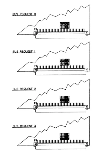
Jumper Settings
The user can select bus request priority from 0 (lowest) to 3 (highest) using the on-board jumpers lAS, lA6, and lA7. All of the possible jumper configurations for this jumper block are illustrated below. To locate the jumper block on the V/ESDI 4201, refer back to Figure 2-1.
BUS REQUEST 0
BUS REQUEST 1
BUS REQUEST 2
[image:34.612.176.481.168.679.2]Installation
In addition to the jumpers for selecting bus priority, there are several other on-board jumpers to configure the V/ESDI 4201 for specific hardware characteristics. Jumper El selects EPROM size (either 256K or 512K) and jumper E4 determines V/ESDI 4201 signal output (either to the on-board headers, or to VMEbus P2). For the physical location of these jumpers for this option, refer back to Figure 2-1.
The unmarked jumpers are for factory use only and should not be changed by the user. The board is shipped with the jumpers in the positions shown in Figure 2-1, at the beginning of this section.
The V/ESDI 4201 is designed to ensure easy installation into the VME system.
Upon receipt of the board, check to make sure that no damage has occurred during shipping. Usually, a thorough visual 'inspection is sufficient since each board is thoroughly checked at Interphase just prior to shi pment.
,
WARNING
The V /ESDI 4201 is extremely sensitive to electrostatic discharge (ESD), and the board could be damaged if it is handled improperly. Interphase ship; the board enclosed in a special anti-static bag. Upon receipt of the board, take the proper measures to eliminate board damage due to ESD (Le., wear a wrist ground strap or other grounding device).
WARNING
Do NOT install or apply power to a damaged ~oard. Failure to obselVe this warning could result in extensive damage to the board and/or system.
If the board is undamaged and all parts are accounted for, proceed with the installation.
1. The first step is to set all on-board jumpers so that the V/ESDI 4201 is properly configured for operation within your system. Those options are discussed at the beginning of this section, and should be reviewed before continuing. The board is shipped from the factory set for Bus Request level 3 and with JA4 jumpered 1-2 (for drive cables connected directly to the
controller rather than to the optional P2 Adapter Card).
V/ESDI 4201 Panther
r
WARNING
System power and disk drive power must be OFF before the V/ESDI 4201 can be installed Failure to do so may result in severe damage to the board and/or system board and/or system.
3. When the power is off, connect the" A" cable (see Appendix A for pin-out details) to the disk drive, making sure that the pins are properly oriented If
only one disk drive is used, it must be attached to the last connector on the cable.
4. Then, install terminators on the last drive on the cable. (If only one drive is connected, the terminators must be connected to that drive.)
5. After routing the "A" cable through the VME system to the proper card slot, connect a "B" cable (see Appendix A for pin-out details) to the disk drive. If
more than one drive is being used, connect a "B" cable to each one, ensuring that the connectors are properly oriented
6. Route the "B" cable to the proper VME card slot, and insert the V/ESDI 4201 about one-third of the way into the slot. Carefully connect the cables as follows:
"A" Cable - J1
"B" Cable - J2 (Drive 0) "B" Cable - J3 (Drive 1) "B" Cable - J4 (Drive 2) "B" Cable - J5 (Drive 3)
7. Carefully slide the board the rest of the way into the slot. It should slide all the way in without any difficulty. If it doesn't, pull it out and check to make sure that the cables are not in the way.
If there is not enough clearance for the board, the cable strain relief may be removed and installation continued
8. Once the board is properly seated in the slot, tighten the captive mounting screws on each end of the board
Overview
3
INITIALIZING THE V /ESDI 4201
The V/ESDI 4201 can control a wide variety of disk drives with differing formats, sizes, and speeds. To accommodate this diversity, the controller must be told which drive is attached to each of the ports, and which options are to be selected before using the drives. The Initialize command provides this information. Each port must be initialized upon power-up and again after every reset.
The V/ESDI 4201 also provides an Initialize Long command. It is used to load an extended UIB, which is required if multiple sector slipping is going to be used on the drive being initialized. The first nine words of both the standard UIB and the extended UIB are identical. However, the extended UIB has seven additional words appended to the end of a standard UIB.
When an Initialize command is issued, the buffer address in the IOPB points to a list of initialization parameters called a Unit Initialization Block (UIB). There are two different UIBs which may be read depending on whether a normal Initialize command (87 hex) or an Initialize Long command (7C hex) is issued The standard UIB contains 18 bytes of information. Upon power-up, the V/ESDI 4201 installs default UIB parameters for each port. The default UIB contains the minimum information necessary t,) read data from a typical ESDI-type drive. This feature allows boot programs to be drive-independent.
Unit Initialization Block
The UIB information for a specific drive can be stored in the first sector of data in that drive. The default UIB allows the host to read this information from the drive and to configure the V/ESDI 4201 to conform to the required drive specifications. The V/ESDI 4201 will not allow any type of Write or Format commands to be executed before an Initialize command has been issued and executed Note that failure to initialize a drive before a Write or Format operation is attempted will result in an error code of 40 (HEX), unit not initialized Since the end of the UIB does not fallon a long word boundary, the V/ESDI 4201 must access the UIB in word mode even if the "memory type" IOPB parameter is set to 03 (long word). The memory type will be changed to 02 by the V/ESDI 4201 if this occurs.
V /ESDI 4201 Panther
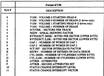
Table 3-1. UIB Format
Format~UIB
Byte' DESCRIPTION
0 VISH - VOLUME 0 STARTING HEAD II
1 VISH - VOLUME 0 NUMBER OF HEADS (2 drives only)
2 VISH - VOLUME 1 STARTING HEAD II (2 drives only)
3 VISH - VOLUME 1 NUMBER OF HEADS
4 ScrtrRK - SECrORS PER TRACK
5 SKEW - SPIRAL SKEWING FACfOR
6 BYTES/Scr (MSB) - BYTES PER SECrOR (UPPER BYTE)
7 BYTES/Scr (LSB) - BYTES PER SECfOR (LOWER BYTE)
8 GAP 1 -NUMBER OF WORDS IN GAP 1
9 GAP 2 -NUMBER OF WORDS IN GAP 2
A scr!NT - SECfOR INTERLEAVE FACTOR
B RETRY - NUMBER OF RETRIES ON DATA ERROR
C CYL (MSB) - NUMBER OF CYLINDERS (UPPER BYTE)
D CYL (LSB) - NUMBER OF CYLINDERS (LOWER BYTE)
E A TTRIB - ATTRIBUTES
F A TTRIB - SECOND A1TRIBUTES SET
10 STATUS CHANGE INTERRUPT LEVEL
11 STATUS CHANGE INTERRUPT VECTOR
V olume Specification: UIB Bytes 0-3
Each drive can be separated into two volumes, and each volume can then be treated as an individual drive. This option is particularly useful when dealing with mixed media such as fixed and removable drives. It should be noted, however, that a drive need not have mixed media to use the volume selections. All fixed or removable drives can also be set up as if they contained two volume.
By specifying where the removable and fixed media starts, each medium can be treated as a separate drive. This prevents head increments from crossing medium boundaries. Bytes 0 and 1 specify the starting head and the number of heads for volume O. Bytes 2 and 3 specify the starting head and the
number of heads for volume 1. If volume 1 does not exist, bytes 2 and 3 must be O.
Sectors/Track: UIB Byte 4
[image:38.614.168.525.91.353.2]Spiral Skew: UIB Byte 5
The spiral skew is used by the V/ESDI 4201 to determine the number of sectors that sector zero is offset from the index pulse. Setting the spiral skew factor allows head adjustments on each track without losing a revolution. This byte is used only during formatting and only when the spiral skew in the IOPB is set to zero. For a more detailed explanation of the use of spiral skew with the V/ESDI 4201, please refer to Appendix A.
Bytes Per Sector: UIB Bytes 6 and 7
These two bytes are the number of data bytes per sector. Overhead bytes such as gaps are not included wen the bytes per sector is specified. The number entered in this field must be even (no half words). The minimum sector size is 256 bytes, and the maximum is 2408 bytes.
Gap 1 Words: UIB Byte 8
GAP 1 is all zeros gap before the header information on each sector. Byte 8 represents the number of words of zeros that are written in GAP 1 during a format only. Refer to Appendix A for suggested Gap 2 settings for specific drives.
Gap 2 Words: UIB Byte 9
GAP 2 is the all zeros gap between the header and the data field on each sector. Byte 9 represents the number of words of zeros that is written in GAP 2 during a Format or Write operation. Refer to Appendix A for suggested Gap 2 settngs for specific drives.
Sector Interleave: UIB Byte A.
The sector interleave determines how the physical sectors are formatted on disk. With byte A set to'!', the se,ctors are formatted with the 1:1 interleave. With byte A set to '2', the sectors are formatted with 2:1. Other interleave factors are determined by setting this byte to the desired number (i.e., '3' =
3:1, '4' =4:1, etc.). Interphase suggests that this byte be set to'!' for optimim performance.
Retry Count: UIB Byte B
V!ESDI 4201 Panther
Number of Cylinders: VIB Bytes C and D
Bytes D and C represent the number of cylinders that the V/ESDI 4201 knows are on the drive. This number is used to determine if a Seek reque~t is valid. Any Seek or implied Seek request for cylinders greater than the known number will result in an error.
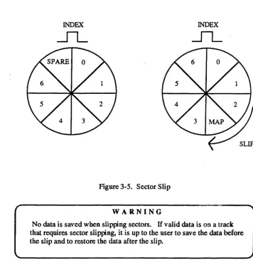
Attributes: VIB Byte E
Attributes such as reseek, move bad data, increment by head, etc. are defined by this byte. Each attribute is designated in the following figure which is then followed by a definition of each.
RSK 1 Reseek
MBD 0 Move Bad Data INH 1 Increment By Head RES 0 Reserved
STC 0 Status Change CE 0 Caching Enable SSE 0 Spare Sector Enable RES 0 Reswerved
Figure 3-1. UIB Attribute Byte E
Bit 7 Reserved
This bit is reserved and must be set to '0' .
Bit 6 Spare Sector Enable
If this bit is set at ' 1 J , it allows the use of a spare sector on each track. The
sector is allocated when the track is formatted. Refer to the Map Sector command in Appendix C for a discussion of sector mapping methods.
Bit 5 Caching Enable
Bit 4 Status Change
If' 1', ~his bit enables an interupt and updating of the Status Change bit in the CSR (or optional status change register) when any unit's status changes (e.g., ready or not ready, explicit seek complete, etc.).
Bit 3 Reserved
This bit is reserved and must be set to '0' .
Bit 2 Increment by Head
If' 1', this bit specifies the increment by head, then cylinder when a track boundary is crossed. If' 0' , increments are done by cy linder, then head at track boundaries. An increment by head scheme is usually preferred since head switch time is much less than cylinder-to-cylinder seek time.
Bit 1 Move Bad Data
If '1', this bit enables the transfer of possibly bad data into system memory.
If the data is still in error after all retries and error correction attempts, and reseeks that are specified have been performed, the V/ESDI 4201 will
normally post an error without transferring any data to system memory. if the Move Bad Data bit is set, the V/ESD1.4201 will move the bad data to system memory (set bit six of the error code byte in the IOPB) and return a Command Completed with &ception status in the IOPB.
Bit 0 Reseek
If' 1', this bit enables a restore and reseek after the retry count has been exhausted on an erroneous data field. The restore and reseek operation is performed after the retry count has been exhausted and prior to applying ECC (if enabled).
Second Attributes Set: UIB Byte F
V /ESDI 4201 Panther
MUTIPLE SPARE ENABLE
ESDI DRIVE TYPE SELECT *(explained below in bits 5 and 4)
FOUR UNIT SELECT
Figure 3-2. VIB Second Attribute Byte F
Bit 6 Four-Unit Select
This bit must be set to '1', if 4 unit operation is required. When this bit is set, the drive number must be selected by setting bits 12 and 13 of the upper byte of IOPB word 8 (or the IOPB interrupt level). If this bit is set, the normal drive number specification bit is no longer used
For 4 unit operation, the Drive Status Registers reside at the base address plus
1FA (hex) and the base address plus 1FC (hex). The DSR at base address IFA (hex) supports unit 3 (in the MSB) and unit 2 (in the LSB), and the DSR at base address +1FC (hex) supports unit 1 (in the MSB) and unit 0 (in the LSB). Also, if this bit is set, then bit 7 of UIB byte 10 (selects Optional Status Change Register) must also be set. The Optional Status Change Register resides at base address +1FE (hex).
Bits S, 4 ESDI Drive Type Select:
These two bits select the type of ESDI drive that is used. The specific types are selected as follows:
00 - Hard Sector Drive 01 - Embedded Servo Drive 10 - Address Mark Drive
Bit 0 • Multiple Spare Enable
This bit must be set to '1' if more than one spare sector will be mapped but may only be set when INIT LONG (command 7C) is used. This bit may not be set if the Spare Sector Enable bit is set in UIB byte E (bit 6). This bit is usually set to '0' .
Status Change Interrupt Level, Register and Vector: UIB Bytes 10 and 11
Extended UIB
Bytes 10 and 11 of the UIB set the level and vector for the Status Change Interrupt for the drive being initialized. The level can be set to any number from one to seven. The vector is the data returned during the VME interrupt acknowledge cycle. Any value is acceptable. If bit 7 of UIB byte 10 is '1', this information is returned in the optional status change register at 1FE instead of the CSR. This bit is ignored if bit 4 in the UIB attributes byte is O.
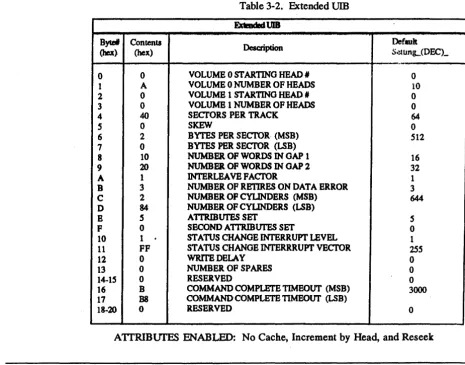
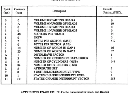
[image:43.615.94.560.359.724.2]The following table shows the format and default settings of the extended UIB which is read when an Initialize Long command (7C) is issued.
Table 3-2. Extended UIB ExtmdedVIB
Bytel Contents
Description Default
(hex) (hex) S~unL(DECL
.-0 0 VOLUME 0 STARTING HEAD, 0
1 A VOLUME 0 NUMBER OF HEADS 10
2 0 VOLUME 1 ST ARTINO HEAD 1# 0
3 0 VOLUMB 1 NUMBER OF HEADS 0
4 40 SECl'ORSPER TRACK 64
S 0 SKEW 0
6 2 BYTES PER SECTOR (MSB) 512
7 0 BYTES PER SECI'OR (LSB)
8 10 NUMBER OF WORDS IN OAP 1 16
9 20 NUMBER OF WORDS IN OAP 2 32
A 1 lNTERLEA VB FACfOR 1
B 3 NUMBER OF RETIRES ON DATA BRROR 3
C 2 NUMBER OF CYLINDERS (MSB) 644
D 84 NUMBER OF CYLINDERS (LSB)
E 5 A1TRIBUI'ES SET 5
F 0 SECOND A1TRIBUI'ES SET 0
10 1
.
STATUS CHANGE INTERRUPT LEVEL 111 FF STATUS CHANGE INTERRRUPT VECTOR lS5
12 0 WRrrEDELAY 0
13 0 NUMBER OF SPARES 0
14-15 0 RESERVED 0
16 B COMMAND COMPLErE TIMEOUT (MSB) 3000
17 B8 COMMANDCOMPLETB TIMEOUT (LSB)
18~20 0 RESERVED 0
V/ESDI4201'Panther
Byte 14, 15, and Bytes 18 through 20 (hex) of the extended UIB are not used at this time and are all reserved. These bytes may be used in future updates to the V/ESDI 4201.
Write Delay: UIB Byte 12
Number or sectors to skip on a zero latency write before attempting to write. Use full to ensure that sufficient data has been prefetched before WR OP begin to preclude disk underrun.
Number of Spares: VIB Byte 13
Byte 13 of the extended UIB is used to specify the number of sectors that will be mapped as spare sectors. Any number of sectors can be used as spares as long as the number is not greater than the number of sectors per track. Also, byte 4 (Sectors/Track) must be altered to reflect the number of usable sectors. In Byte 4, enter the number of sectors per track minus the number of spares specified.
Co·mmand Complete Timeout (MSB and LSB): VIB Byte 16 and 17
Default UIB
The maximum amount of time the controller will wait (in milliseconds) for command complete from the ESDI drive before timing out.
Table 3-3. Default UIB
Byte#
Contents
Description
Default(hex) (hex) Setting_ (DEC)_
0 0 VOLUME 0 STARTING HEAD # 0
1 A VOLUME 0 NUMBER OF HEADS 10
2 0 VOLUME 1 STARTING HEAD # 0
3 0 VOLUME 1 NUMBER OF HEADS 0
4 40 SECTORS PER TRACK 64
5 0 SKEW 0
6 2 BYTES PER SECTOR (MSB) 512
7 0 BYTES PER SECTOR ~B)
8 10 NUMBER OF WORDS IN GAP 1 16
9 20 NUMBER OF WORDS IN GAP 2 32
A 1 INTERLEA VE FACTOR 1
B 3 NUMBER OF RETIRES ON DATA ERROR 3
C 2 NUMBER OF CYLINDERS (MSB) 644
D 84 NUMBER OF CYLINDERS ~B)
E 5 ATIRmUTES SET 5
F 0 4 UNIT SELECTIESDI DRIVE-TYPE 0
10 1 STATUS CHANGE INTERRUPT LEVEL 1
11 FF STATUS CHANGE INTERRRUPT VECTOR 255
V /ESD I 4201 Panther
Initialization of Disk Media
Before a disk can be put into service, it must first be formatted The format provides all header information to be recorded for each sector on a track along with a dummy data field that can later be overwritten. The header information tells the V/ESDI 4201 where the ReadlWrite head is located so that proper position can be ascertained before data transfers are attempted. The remainder of this section will focus on means to improve disk
performance by taking advantage of several V/ESDI 4201 features and functions.
A hard disk drive unit is typically made up of a number of disk platters witb two sides (surfaces) each. Each surface contains a number of concentric tracks which are further divided into sectors. The term cylinder refers to the three-dimensional cross section of a given track (radially coincident) on a stack of platters. The term is sometimes used interchangeably with the term track. However, a track is really specified by a combination of a cylinder number and head number.
TRACK
SECTORS
CYLINDER
Figure 3-3. Typical Disk Unit
In addition, the optimum number of sectors per track should be set before the disk drive is formatted. This parameter is usually specified on ESDI devices by setting switches on the drive (refer to the drive manual for specific details). The number ef sectors per track determines the number of bytes in each sector. This is impQrtant because, in addition to the data field, each sector must be large enough to accommodate any overhead required by the disk drive and the controller to operate properly. (Drive overhead includes the PLO synchronization time and the length of the write splice. Controller overhead includes the header field, the ECC field, and the space between the sector pulse, header field and data field.)
Sector Pulse
Gap 1
j
Gap 2(PLO) WRITE ~ Zero
SPUCE ~ User Data ECC p~
(Sync)
=
(PLOSync) til.~ .~ ~.
L
,,88 ytes OF 004 B y':'e5~ cf EC
c
16 Bits of Sync (1001100110011001)
Normal Header IS 14 13 12 11 10 9 8 7 6 S 4 3 2 1 0 1 0 1 0 1
I
cvlinder numberbeadnumber'
I
sector nmnberbeadnumber' I sector nwnber
0 o 0 0 0 0 000 0 0 0 0 000
MappedH~ IS 14 13 12 11 10 9 8 7 6 5 4 3 2 1 0
1 1 0 1
of
defect cYlinder number defect head number I target head no.target "'Y UI~ number
0 o 0 0 000000000000