Cite this:Chem. Soc. Rev.,2019,
48, 4424
Interface design for high energy density
polymer nanocomposites
Hang Luo,†aXuefan Zhou,†aChristopher Ellingford, b Yan Zhang, ac Sheng Chen,dKechao Zhou,aDou Zhang, *aChris R. Bowen *cand Chaoying Wan *b
This review provides a detailed overview on the latest developments in the design and control of the interface in polymer based composite dielectrics for energy storage applications. The methods employed for interface design in composite systems are described for a variety of filler types and morphologies, along with novel approaches employed to build hierarchical interfaces for multi-scale control of properties. Efforts to achieve a close control of interfacial properties and geometry are then described, which includes the creation of either flexible or rigid polymer interfaces, the use of liquid crystals and developing ceramic and carbon-based interfaces with tailored electrical properties. The impact of the variety of interface structures on composite polarization and energy storage capability are described, along with an overview of existing models to understand the polarization mechanisms and quantitatively assess the potential benefits of different structures for energy storage. The applications and properties of such interface-controlled materials are then explored, along with an overview of existing challenges and practical limitations. Finally, a summary and future perspectives are provided to highlight future directions of research in this growing and important area.
1. Introduction
Polymers are a key element in energy harvesting and storage devices due to their unique properties in comparison with traditional ceramic and metallic materials, such as high break-down strength, mechanical flexibility, low density, ease of processing and low cost.1–6Today, functional polymer compo-sites are attracting interest in an increasing number of applica-tions, including polymer based dielectric capacitors which are widely employed in the areas of power transmission, hybrid
aState Key Laboratory of Powder Metallurgy, Central South University, Changsha,
Hunan 410083, China. E-mail: [email protected]
b
International Institute for Nanocomposites Manufacturing (IINM), WMG, University of Warwick, CV4 7AL, UK. E-mail: [email protected]
cDepartment of Mechanical Engineering, University of Bath, Bath, BA2 2ET, UK.
E-mail: [email protected]
dKey Laboratory of Polymeric Materials and Application Technology of Hunan
Province, College of Chemistry, Xiangtan University, Xiangtan 411105, Hunan Province, China
Hang Luo
Hang Luo obtained his PhD degree in Material Science and Engineer-ing from Central South University in 2016, and he continued post-doctoral studies in Chemistry at Central South University. He has worked as an Associate Professor at the State Key Laboratory of Powder Metallurgy, Central South University since 2017. His work has concentrated on interface design, polymer based dielectrics for energy storage and ferro-/
piezo-electric ceramics. Xuefan Zhou
Xuefan Zhou obtained her BSc degree in Material Engineering from Central South University in 2017. She is currently a PhD student at the Powder Metallurgy Research Institute of Central South University. Her PhD work focuses on sodium bismuth titanate based lead-free piezoelectric ceramics for enhancing their piezoelectric properties and strain response. In addition, she also studies dielectric capacitors for energy storage applications.
†These authors contributed equally to this work.
Received 30th March 2019
DOI: 10.1039/c9cs00043g
rsc.li/chem-soc-rev
REVIEW ARTICLE
Open Access Article. Published on 04 July 2019. Downloaded on 8/21/2019 5:12:11 PM.
This article is licensed under a
Creative Commons Attribution-NonCommercial 3.0 Unported Licence.
electric vehicles, high power weapons, radar, wind power gen-eration, and microelectronic systems; these sectors are sum-marized in Fig. 1. As an example, a converter valve is used for the conversion of an alternating current (AC) into a direct current (DC) in high voltage direct current (HVDC) transmis-sion engineering, and in such a system the dielectric capacitors occupy over 50% of the volume. Polymers are preferred due to their advantages in terms of excellent electrical properties and ease of forming in continuous and large area dielectric films with a tailored thickness in the micrometer range. Table 1 provides a summary for a variety of current dielectrics in polymeric and ceramic form.3,7–14The dielectric material often employed in commercially available capacitors is biaxially oriented polypropylenes (BOPP). However, the mismatch between ambient temperature (B140 1C) and the maximum
operating temperature (B105 1C) of BOPP can become a
limitation to its application.15 In this case, high-temperature dielectric materials, such as polyethylene naphthalate (PEN), polyphenylene sulfide (PPS), poly(ethylene terephthalate) (PET)
and polyimide (PI) have been developed.7 Another important commercially available capacitor system is the multi-layer ceramic capacitor (MLCC), where the mainstream dielectric is the BaTiO3 or doped-BaTiO3 ceramics.16 Compared with the
capacitors formed from bulk ceramics, MLCC possesses high capacitance (e.g.1–100mF), small volume (e.g.0.6 by 0.3 mm2),
high reliability, and excellent high-frequency characteristics.17 In addition, MLCCs can endure a relatively high electric field due to the small thickness of the individual layers, of the order of several microns, compared with bulk ceramic capacitors whose dimensions are several hundred microns.18 Recently, electroactive polymers with high relative permittivity, such as ferroelectric poly(vinylidenefluoride) (PVDF) and its co/ter-polymers, and ceramic/polymer composites have been inten-sively studied due to their high permittivity and high break-down strength. A comparison to show the ranges for different energy storage devices are summarized in Table 2, where the advantages of polymer based dielectric capacitors include high power density, high efficiency, stability and low cost compared
Sheng Chen
Sheng Chen received his PhD degree in Polymer Chemistry and Physics from Xiangtan University in 2013. After graduation, he worked in the College of Chemi-stry in Xiangtan University as an Associate Professor. His research interests include the design, synthesis and phase structure of liquid crystalline polymers, and energy storage of polymer-based nanocomposites.
Dou Zhang
Dou Zhang obtained his PhD degree in Metallurgy & Materials from University of Birmingham in 2006. He is currently a Professor in Powder Metallurgy Research Institute of Central South Univer-sity. His research is focused on ferroelectric ceramics for energy and microwave applications; piezo-electric ceramics and composites as sensors and actuators; porous ceramics; bioceramics; ceramic microsystem techniques, including colloidal micromoulding and 3D printing. Particular attentions are paid to the controllability of fine scale structures and their impact on device performance.
Chris R. Bowen
Christopher Rhys Bowen has a BSc degree in Materials Science from the University of Bath
(1986–1990) and a DPhil
from the University of Oxford (1990– 1993). Post-doctoral work was at Tecnische Universita¨t Harburg-Hamburg and University of Leeds (1994–1996). He was Senior Scientist at the Defence Eva-luation and Research Agency from 1996–1998. He joined Bath as a Lecturer in 1998 and is now Pro-fessor of Materials, where research includes energy harvesting, ferro-electrics and functional ceramics.
Chaoying Wan
Dr Chaoying Wan is Associate Professor in multifunctional nano-composites at the University of Warwick, UK. She obtained a PhD degree in Materials Science in 2004 at Shanghai Jiao Tong University. She was awarded a Marie Curie Fellowship and worked at Trinity College Dublin between 2009 and 2011. She specialises in polymer synthesis and characterisation of multiphase/ multicomponent nanocomposites, smart dielectric elastomers and sustainable rubbers for energy applications.
Open Access Article. Published on 04 July 2019. Downloaded on 8/21/2019 5:12:11 PM.
This article is licensed under a
with other energy storage devices such as lithium ion batteries and supercapacitors.7,19–27
In order to enhance polymer properties for applications, such as those in Fig. 1, a wide variety of polymer based composite systems are being explored. These are based on a polymer matrix that contains organic, ceramic, and carbon-based fillers that can be either randomly dispersed, aligned or ordered in a multi-layer form.28–32 The properties of polymer composites do not solely rely on the structure and properties of the individual components, since we will see in this review that interfacial interactions between the matrix and filler has an important role in determining the overall performance.33–35
In such composite systems, an additional third phase, namely the interfacial region is introduced and due to the high specific surface area of nanoscale fillers, the volume ratio of the interfacial phase can be as high as 50–70 vol%. As a con-sequence, the interfacial properties can have a significant impact on the overall performance of nanocomposites and their devices.
For a linear dielectric capacitor, the energy stored is related to the working voltage (V) and the capacitance (C):1
2CV 2, the
‘‘energy density’’ is therefore given by eqn (1):
1=2CV2 vd
¼1 2ere0Eb
2 (1)
where vd is the volume of the capacitor material, er is the
relative permittivity,e0is the permittivity of free space andEb
is the dielectric strength.8,11,36This leads to a merit index of
er(Edielectric)2 for the maximum energy density (J m3). The
energy storage performance is also influenced by the dielectric loss (oe00e
0; whereois angular frequency ande00 is imaginary
permittivity), and the associated tand = e00/e0. The dielectric
displacement as a function of applied electric field should also be considered in order to account for material non-linearities, which are often observed at high electric field, and avoid the above simplification of assuming a linear dielectric response.16,37–39
For polymer based nanocomposite systems, the surface modification of inorganic fillers using organic modifiers is often employed to enhance the interfacial interaction, material compatibility, and dispersion of the filler in a polymer matrix. However, the mismatch of relative permittivity or electrical conductivity between the inorganic fillers and polymer matrix often leads to the development of an inhomogeneous electric field distribution throughout the composite, and generally
Table 1 Summary of the properties of dielectrics for capacitor applications, which include biaxially oriented polypropylenes (BOPP), polyethylene naphthalate (PEN), polyphenylene sulfide (PPS), poly(ethylene terephthalate) (PET), polyimide (PI), poly(vinylidenefluoride) (PVDF) and multi-layer ceramic capacitor (MLCC)
Dielectrics for capacitors
Relatively permittiv-ity (1 kHz)
Dielectric loss (1 kHz)
Breakdown strength
(kV mm1) Max. operating tem-perature (1C) (W (m K)Thermal conductivity1) Energy density(J cm3)
BOPP 2.2 B0.0002 B640 105 2.1–2.35 1–1.2
PEN 3.2 B0.0015 B550 125 B0.26 1–1.5
PPS 3.0 B0.0003 B550 200 B0.3 1–1.5
PET 3.6 B0.005 B570 125 0.29 1–1.5
PI 3.5 0.04 B238 B200 6.58–11.7 1.4
PVDF and its co/ter-polymer
B410 B0.02–0.2 B200–600 125 B0.24 B44
Ceramics/polymer composites
B50 B0.02–0.08 B300–500 B150 — B10–30
MLCC B100–3000 — — B125 — B10
Bulk ceramics B102–4103 — B10–50 B200 — B1–7
Table 2 Comparison of key performance indicators for a variety of energy storage devices
Energy storage devices Power density (W kg1) Energy density (W h kg1) Efficiency Stability Cost
Dielectric capacitor B104–107 B102–101 High Good Low
Supercapacitor B4104 Bo10 Low Good High
Lithium-ion batteries Bo1000 B150–250 High Low Low Fig. 1 The emerging applications of dielectric capacitors.
Open Access Article. Published on 04 July 2019. Downloaded on 8/21/2019 5:12:11 PM.
This article is licensed under a
leads to a significant reduction of the breakdown strength of dielectric composites. We will see later in this review that this is due to the electric field being concentrated in the low permittivity phase as a consequence of Gauss’ law.40,41 This
field concentration can be overcome to some extent by con-structing an inorganic shell layer, grafting multifunctional organic shell layers, using multiple hierarchical shells on the surface of the fillers and building topological structures, including sandwiched or multi-layered structures.
The aim of this review is to overview the important role of the interface and interphase to allow tailoring of the properties of nanocomposite dielectrics. Polymer nanocomposites for energy storage applications continues to be a growing area that has attracted increasing discussion via a variety of existing reviews. These include a wide variety of key topics, which include an examination of PVDF and its copolymers, and their nanocomposites for high energy density capacitor applica-tions;7,8,11,22,42–45 high-temperature dielectric nanocompo-sites;10,15 high-k dielectrics;18,46,47 recent achievements on
BaTiO3nanomaterials and their synthesis, dielectric and
ferro-electric properties;48dielectric and energy storage properties of
polymers and multilayered dielectrics films;3,49,50ceramic films and bulk ceramics for energy storage capacitors;12,16,25,32,51the effects of fillers on the dielectric and energy storage properties of polymer composites;2,52 carbon based polymer composites for energy storage;9,53,54polymer based nanodielectric design for advanced capacitors;45,55,56interface engineering in polymer nanocomposites to improve energy storage;36,57and the strategies for engineering the surfaces of fillers.58
This review will cover methods of interface design by intro-ducing the range of interface layers and structures. Examples include the creation of core–shell structures that use organic, insulating ceramic (dielectric) and electrically conductive outer-layers on nano-fillers; including sandwich and multi-layer architectures (Section 2). The efforts to create multiple shells
with hierarchical and controlled graded structures to further improve nanocomposite performance are discussed (Section 3). The effect of the interface on polarization mechanisms, break-down strength and growth of defects is then discussed. There is an in-depth examination of the influence of filler morphology, such as filler dimensionality, aspect ratio and volume fraction, along with an overview of the variety of models being developed for prediction of properties and understand effective properties (Section 4). Specific examples of interfacial design strategies and its impact for high performance energy storage capacitors are discussed (Section 5). Finally, an outlook and future per-spectives of high-performance polymer composite capacitors are proposed.
2. Architectures for interface design
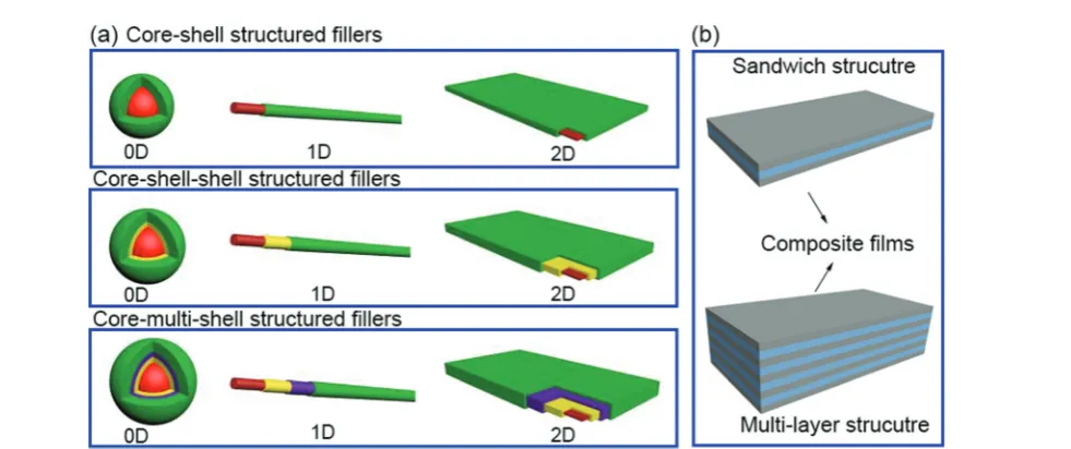
In this section we will provide an overview of the interface types observed in dielectric nanocomposites, as shown in Fig. 2. The fillers can be considered at a range of dimensions,59–61namely
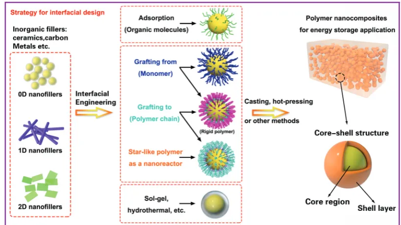
zero dimensional (0D) nanofillers which include spherical nanoparticles, nanocubes and nanoparticles with irregular morphologies, one dimensional (1D) nanofillers which include nanowires, nanofibers, nanotubes and nanoribbons, and two dimensional (2D) nanofillers which include nanosheets and nanoplatelet, as shown in the left column of Fig. 3. The outer surface of the fillers can be coated with a range of materials, as seen in the center column of Fig. 3, which can be used to tune the interface between filler and matrix; see right column of Fig. 3.
The strategies of core shell synthesis including adsorption, grafting from, grafting to, star-like nanoreactors and sol–gel/ hydrothermal approaches will now be described based on organic or inorganic shells, hierarchical outer layers (Fig. 2a), and multi-layer structures (Fig. 2b). As a representative struc-ture, 0D nanofillers will be firstly covered used to describe
Fig. 2 (a) Core–shell structured fillers including core–shell, core–shell–shell and core–multi-shell structures in 0D, 1D and 2D form, (b) composites films including sandwich and multi-layer structures.
Open Access Article. Published on 04 July 2019. Downloaded on 8/21/2019 5:12:11 PM.
This article is licensed under a
[image:4.595.61.552.486.692.2]the processes of interfacial engineering and nanocomposite preparation.
2.1 Theory of surface energies
Ceramic fillers such as Pb1xZrxTiO3 (PZT), BaTiO3, TiO2,
Ba1xSrxTiO3 (BST), and carbonaceous particles such as
graphene and carbon nanotubes (CNT) are often incompatible with the polymer matrix due to the significant difference in surface energy compared to the matrix and poor polymer– particle interfacial interactions.62 Inorganic fillers therefore
tend to form agglomerates within polymer matrices which results in phase separation and poor properties.
Nano-scale fillers can readily agglomerate easily due to their high surface energy, high van der Waals forces or high electro-static forces, resulting in the poor dispersity in the polymer matrix. The surface energy of a material is defined as the excess energy per unit area due to the existence of a free surface; it can also be the thermodynamic work done per unit area of surface extension. When the filler material possess a high surface energy, they tend to agglomerate in order to form a more stable lower energy state. Generally, high-surface energy materials include metals, metal oxides, and inorganic compounds (such as sapphire, nitrides, oxides, silica, and diamond), which exhibit dense, refractory, and hard properties, where the surface energy values of such materials is approximately 200–5000 dyn cm1. Organic polymers, which act as the com-posite matrix, are typically low surface energy materials, where the surface energy is approximately 10 and 50 dyn cm1. The reader is referred to the work of the Menachem Lewin group for a summary of surface tensions and surface energy values of these materials,63 where the values of a range of polymers,
minerals, oxides and clays based on theoretical calculations or empirical equations were also presented. In order to account for the difference of surface energy between the polymer-based matrix and inorganic fillers, the high-energy surfaces of inorganic fillers are often coated with low-energy surface materials, such as siloxane coupling reagents or polymers, whereby a thin layer can reduce the surface energy of inorganic fillers. Therefore, the design and construction of an interfacial layer using modifiers with different function properties is an attractive approach to enhance the dispersion properties of inorganic nano-scale fillers. Additional approaches to increase the compatibility between the filler and polymer matrix can be to exploit electrostatic interactions, hydrogen bonding or dipole–dipole interactions, which is summarized in Fig. 4.
2.2 Core–shell structure
To date, core–shell structured nanoparticles have been explored in depth for surface modification and multi-functional applications.64–67In polymer based nanocomposites, the ability to enhance dispersion of nanofillers and tailor the interfacial proper-ties remain important technical challenges to be addressed68–70 and the surface modification of fillers with a variety of organic modifiers is an effective approach to overcome these issues.71,72 Organic modifiers can be physically adsorbed onto the filler surface through electrostatic interactions or by hydrogen bonding. A variety of modifiers have been used, as shown in Fig. 5, which include dopamine,73,74 silanes,75 phosphonic acid,76 ethylene diamine,77 polyvinyl alcohol,78 and paraffin.79 These organics have been utilized to modify the surfaces of inorganic fillers and are of interest due to their simple treatment process, for example by solution mixing. Alternatively, the organic shell can be
Fig. 3 General methods associated with the design and control the interface of core–shell structured fillers for dielectric capacitor application. The left column shows the range of filler types, the central column indicates the core–shell interfacial control methods and the right column shows the final nanocomposite structure.
Open Access Article. Published on 04 July 2019. Downloaded on 8/21/2019 5:12:11 PM.
This article is licensed under a
[image:5.595.91.501.50.280.2]chemically grafted onto the filler surfaces via ‘‘grafting to’’ or ‘‘grafting from’’ approaches through living/controlled free radical polymerization or click-chemistry reactions. The ‘‘grafting from’’ approach relies on the formation of a core–shell structure by the
in situ polymerization of monomers on initiator-functionalized nanoparticle surfaces. In contrast, the ‘‘grafting to’’ approach leads to the formation of a core–shell structure by grafting the pre-prepared polymer chains onto the nanoparticle surfaceviaa reaction between the polymer end-groups and the functional groups on the nanoparticle surface. Moreover, an additional strategy for the creation of a well-defined nanoparticle/polymer
core–shell structure was developed using star-like polymers as nanoreactors; see central column of Fig. 3. These three methods will be examined in more detail in Section 3.1.
Table 3 summarizes the range of organic modifiers that have been employed to date for improving filler dispersion and compatibility in dielectric nanocomposites. The development of an organic shell not only improves interface compatibility between the polymer matrix and inorganic fillers, it can also prevent the inner core from agglomerating and thus improve filler dispersion. As an example, dopamine has been used for surface modification of a variety of filler particles80due to its versatile ‘‘adhesive’’ properties and its ability to readily form a polydopamine layerviaself-polymerization at ambient condi-tions. Dopamine modified BaTiO3 nanofibers have an
amor-phous layer with a thickness ofB5 nm, which have resulted in an improvement of relative permittivity byB20% and break-down strength byB100% compared to epoxy composites with BaTiO3 nanofibers.73 The use of physically adsorbed organic
modifiers leads to the presence of free residual species in the composite, which can lead to increased leakage currents and increased dielectric loss.75,81 In contrast, chemically grafted
polymer layers may overcome this problem due to its covalently bonded nature.82,83
Fluoro-polymers, such as PVDF and its copolymers, are generally immiscible with a number of inorganic fillers due to their low surface energy. Although a number of strategies have been used to modify nanofillers using a hydrocarbon modifier, this continues to result in filler agglomeration and the creation of voids and defects in the nanocomposite films which can initiate dielectric breakdown.84 To overcome this challenge, a fluoro-phosphonic acid has been used to engineer the surface of BaTiO3nanoparticles, and effectively reduce its
surface energy. This resulted in a good dispersion of the nanoparticles in poly(vinylidene fluoride-co-hexafluoro propylene) (P(VDF–HFP)) based composites.85In addition, a series of core–
shell structured BaTiO3@fluoro-polymer hybrid nanoparticles
with a variety of shell structures and thicknesses were prepared
via a surface-initiated Reversible Addition–Fragmentation Chain Transfer Polymerization (RAFT) polymerization, which led to uniformly dispersed BaTiO3nanoparticles in the polymer
matrix and thereby improved the electrical properties of the nanocomposites.86These reports demonstrate that the use of a fluoro-polymer is a promising route to modify and engineer the surface of ceramic fillers. The fluorine atoms from the modifier and matrix can reduce the mismatch of interfacial properties, and since fluorine atoms possess a high electronegativity they can easily form hydrogen bonds with hydrogen atoms from the modifiers and polymer matrix.
The organic modifiers described above with long hydrocar-bon chains generally possess a lower relative permittivity compared to ceramic fillers and the PVDF homopolymer or copolymer matrix. It has been shown that a large difference in relative permittivity between an inorganic ceramic filler and the polymer matrix leads to an inhomogeneous electric field distribution, since electric fields tends to concentrate in phases of low permittivity.40,41 Therefore, the introduction of a
Fig. 4 Schematic of the range of interactions between the core–shell structured filler and polymers matrix.
Fig. 5 Examples of organic modifiers for surface engineering of a ceramic filler particle, in this case BaTiO3.73–79
Open Access Article. Published on 04 July 2019. Downloaded on 8/21/2019 5:12:11 PM.
This article is licensed under a
high-permittivity inorganic filler will lead to a decrease in the composite breakdown strength as a result of an electric field concentration formed in the interfacial region. Therefore, the ability to decrease the permittivity contrast between the filler and polymer matrix of a nanocomposite is potentially an effective route to enhance the breakdown strength and energy storage density; see eqn (1). This can be achieved by introducing a low-permittivity ceramic shell layer on the surface of the high-permittivity nanofiller to mitigate the permittivity mismatch between the filler particle
and polymer matrix. A number of examples are shown in Table 4, which demonstrate that TiO2,87Al2O3,88,89and SiO2,90–93have been
often chosen as the buffer layer due to their intermediate relative permittivity which is of a magnitude between that of the high-permittivity filler and low-high-permittivity polymer matrix. Fig. 6 shows the microstructure of 2D Bi2Te3@Al2O3nanoplates, where a
uni-form Al2O3shell has been successfully formed on the surface.89The
materials selected also exhibit a low dielectric loss; for example Al2O3,erB10,94SiO2, tandB0.0002.95
Table 3 Summary of the range of modifiers used for filler surface modification in dielectric nanocomposites. The filler type, filler morphology and polymer matrix are also indicated
Filler
Morphology
of the fillers Polymer matrix Modifier Method Ref.
BaTiO3 0D P(VDF–HFP) Phosphonic acid Surface absorption 76
BaTiO3 0D PVDF Carboxylic acids Surface absorption 96
BaTiO3 0D Poly(vinyl alcohol) (PVA) Gallic acid (GA) Surface absorption 97
BaTiO3 0D PVDF Polyvinylprrolidone (PVP) Surface absorption 98
BaTiO3 0D PVDF Titanate coupling agent Surface absorption 99
BaTiO3 0D PVDF PVP Surface absorption 100
Ba(Fe0.5Ta0.5)O3 0D PVDF Dopamine Polycondensation 101
BaTiO3 0D Poly(vinylidene fluoride-co
-chlorotrifluoroethylene) (P(VDF–CTFE))
GA Polycondensation 102
BaTiO3 0D PVDF Polydopamine Polycondensation 73
SiO2 0D P(VDF–HFP) Fluoride 1H,1H,2H,2H
-perfluorooctyltriethoxy-silane
Grafting to 103
BaTiO3 0D P(VDF–HFP) Hydantoin epoxy Grafting to 104
BaTiO3 0D Glycidyl methacrylate
functionalized P(VDF–HFP)
Amino-terminated silane molecules Grafting to 105
Al2O3 0D Polypropylene Phosphonic acid-terminated
poly(ethylene-co-1-butene)
Grafting to 106
BaTiO3 0D Poly(vinylidene
fluoride- trifluoroethylene-chlorotrifluoroethylene (P(VDF–TrFE–CTFE))
Poly(2,5-bis[(4-trifluoromethoxyphenyl) oxycarbonyl]styrene) (PTFMPCS)
Grafting from 107
BaTiO3 0D Poly(methyl methacrylate)
(PMMA)
PMMA Grafting from 108
BaTiO3 0D Poly(2-hydroxylethyle
methacrylate) (PHEMA)@PMMA
PHEMA@PMMA or
poly(acrylate)sodium@PHEMA
Grafting from 109
BaTiO3 0D PMMA PMMA Grafting from 110
BaTiO3 0D Poly(vinylidene
fluoride- trifluoroethylene-chlorofluoroethylene) (P(VDF–TrFE–CFE))
Hyperbranched aromatic polyamide (HBP)
Grafting from 111
BaTiO3 0D HBP@PMMA HBP@PMMA Grafting from 83
BaTiO3 0D P(VDF–HFP) Poly(trifluoroethyl acrylate) (PTFEA) Grafting from 86
BaTiO3 0D Polystyrene Polystyrene Grafting from 112
SrTiO3 1D PVDF PVP Surface absorption 113
BaTiO3 1D P(VDF–HFP) Fluoro-polydopamine Surface absorption 114
Ba0.8Sr0.2TiO3 1D PVDF Ethylenediamine Surface absorption 115
BaTiO3 1D P(VDF–TrFE–CFE) Ethylenediamine Surface absorption 116
SrTiO3 1D PVDF Dopamine Polycondensation 117
0.5Ba(Zr0.2Ti0.8)O3–
0.5(Ba0.7Ca0.3)TiO3
1D PVDF Polydopamine Polycondensation 118
Ba0.6Sr0.4TiO3 1D PVDF H2O2 Oxidation 119,120
MWCNT 1D Polypropylene Poly(ethylene-co-butylene)–OH Grafting to 121 MWCNT 1D P(VDF–HFP) Methoxypolyethylene glycol (mPEG) Grafting to 122 NaNbO3 1D PVDF Polydopamine Polycondensation 123
BaTiO3 1D P(VDF–HFP) PMPCS Grafting from 124
Na2Ti3O7 1D P(VDF–HFP) PMPCS Grafting from 125
Reduced graphene oxide (RGO)
2D PVDF PVA Surface absorption 126
BaTiO3/graphene 2D P(VDF–HFP) Polydopamine Polycondensation 127
Graphene oxide 2D Nitrile butadiene rubber g-Aminopropyl triethoxysilane Condensation reaction 128 Boron nitride 2D PVDF Hydroxyl groups Oxidation 71 Graphene-oxide 2D PI p-Phenylenediamine Grafting to 129 Graphene 2D Poly(p-phenylene
benzobisoxazole)
Hyperbranched aromatic polyamide Grafting from 130
Open Access Article. Published on 04 July 2019. Downloaded on 8/21/2019 5:12:11 PM.
This article is licensed under a
Rahimabadyet al.87prepared P(VDF–HFP) based nanocompo-sites using TiO2coated BaTiO3nanoparticles (BaTiO3@TiO2). The
relative permittivity,er, of the P(VDF–HFP) nanocomposite with
50 vol% BaTiO3@TiO2at 1 kHz was increased toerB110, which
is over three times higher than BaTiO3/P(VDF–HFP)
nanocompo-sites due to the strong interfacial interaction and space charge accumulation at interfaces. The enhanced polarization was attributed to a highly interactive interface between the multiple dielectric materials due to the introduction of an intermediate TiO2layer. The results showed that nanocomposites with a core–
shell structured filler achieved a higher breakdown strength compared to BaTiO3/P(VDF–HFP) nanocomposites. The reasons
for the improved breakdown strength include the introduction of an inorganic TiO2shell with an intermediate relative permittivity
between the BaTiO3filler and P(VDF–HFP) matrix, which reduced
the local electric field concentration. The TiO2 shell was also
thought to tightly adhere to the polymer matrix and both factors
can act to enhance the breakdown strength of the nanocompo-sites. As an alternative approach, a graded dielectric filler was proposed by Huanget al.131to overcome the paradox of attempt-ing to achieve an improved breakdown strength and increased relative permittivity in nanocomposite systems. This included the use of a shell layer with an intermediate relative permittivity (such as TiO2,erB40), a high-permittivity core (BaTiO3,erB1000) and
a polymer matrix (e.g.P(VDF–HFP),erB10). The use of a gradient of dielectric fillers resulted in not only an enhanced interfacial polarization induced by the TiO2 nanowire layer grown on the
BaTiO3nanoparticles, but also improved the breakdown strength
by smoothing the inhomogeneous electric field distribution within the composite.
In addition to inorganic dielectrics at the interface, inorganic conductive materials, such as carbon, have been considered as a novel interfacial modifier to modulate the performance of dielectric nanocomposites. Yanget al.prepared a novel core–shell structure including TiO2 nanowires that
acted as a core and a conductive carbon layer as the shell which was formed by a hydrothermal reaction and chemical vapor deposition (CVD) processes, as shown in Fig. 7.132From
the SEM image of the TiO2@C, it was found that the carbon
layer on the surface of TiO2 nanowires was compact and
smooth, and the interface thickness could be precisely modulated by controlling the duration of the CVD process. It is of interest to note that this work discovered a novel strategy to tailor the dielectric properties of PVDF based nanocomposites by
Table 4 Summary of the range core–shell fillers with inorganic ceramic or carbon shells. The core material and its morphology, the shell materials and the polymer matrix are indicated
Core Morphology of the filler Shell Matrix Method Ref.
BaTiO3 0D TiO2 P(VDF–HFP) Hydrothermal 131
Ag 0D TiO2 Polytetrafluoroethylene Sol–gel 133
BaTiO3 0D Al2O3 PVDF Heterogeneous nucleation 88
Ceramic 0D Al2O3 Polyolefin Metallocene polymerization 134
BaTiO3 0D Fe3O4 PVDF Chemical precipitation 135
BaTiO3 0D Fe3O4 PVDF Chemical precipitation 136
CCTO 0D Fe3O4 PI Hydrothermal 137
BaTiO3 0D SiO2 PVDF Hydrolysis reaction 91
BaTiO3 0D SiO2 PVDF Sto¨ber method 95
Zn 0D ZnO PVDF Calcination 138
BaTiO3 1D TiO2 PVDF Hydrothermal 139
BaTiO3 1D TiO2 PVDF Electrospinning 140
BaTiO3 1D TiO2 PVDF/P(VDF–HFP) Electrospinning 141
BaTiO3 1D TiO2 P(VDF–HFP) Kinetics-controlled coating 142
BaTiO3 1D Al2O3 PVDF Electrospinning 143
BaTiO3 1D Al2O3 PVDF Electrospinning 94
SiC 1D SiO2 PVDF Sol–gel 144
Bi2S3 1D SiO2 PVDF Sol–gel 145
BZT–BCT 1D CoFe2O4 PVDF Sol–gel and electrospinning 146
BaTiO3 1D SiO2 PI Electrospinning 147
BaTiO3 1D SiO2 PVDF Hydrolysis reaction 92
Bi2Te3 2D Al2O3 PVDF Sol–gel 89
Bi2Te3 2D SiO2 P(VDF–HFP) Sol–gel 90
BaTiO3 0D C P(VDF–HFP) CVD 148
SiO2 0D RGO Epoxy Electrostatic assembly 149
BaTiO3 0D Ag PVDF Deposition 150
Ag 1D C PVDF Hydrothermal 151
BaTiO3 0D Ag@polydopamine P(VDF–HFP) Chemical precipitation and absorb 152
TiO2 1D C@SiO2 PVDF CVD and sol–gel 153
BaTiO3 1D TiO2@Al2O3 PVDF Electrospinning 154
BaTiO3 1D Polydopamine–Pt P(VDF–HFP) Polycondensation and reduction reaction 155
Fig. 6 (a) SEM image of 2D Bi2Te3nanoplates; (b) TEM image, and (c)
HRTEM image of 2D Bi2Te3@Al2O3nanoplates. Reproduced from ref. 89
with permission from the Royal Society of Chemistry.
Open Access Article. Published on 04 July 2019. Downloaded on 8/21/2019 5:12:11 PM.
This article is licensed under a
tuning the carbon shell thickness. In addition, a novel percolative dielectric nanocomposites was formed with enhanced relative permittivity by introducing a small loading level of TiO2@C
nanowires; for example, the highest relative permittivity achieved was toerB2171 at 1 kHz, which was 80 times higher than the
composite fillers with untreated TiO2nanowires at the same filler
loading level.
2.3 Building hierarchical interfaces
Interfacial polarization is a dominant factor affecting the perfor-mance of polymer nanocomposites,57,156due to the mismatch in
relative permittivity and electric conductivity of the interfacial layer between the polymer matrix and filler particles.129,130 As
discussed in Sections 2.2 and 2.3, simple core–shell structures formed using organic or inorganic modifiers are effective routes to improve energy storage performance. This core–shell approach can be enhanced by the use of multiple-shells to provide a hierarchical functional interface layer. Such as structure, as shown in Fig. 2, can further assist in the dispersion, polarization, buffering, or shielding. For example, the use of an outer disper-sion layer can contribute to the disperdisper-sion and interfacial inter-action of the ceramic fillers in the polymer nanocomposites, while an inner polarization layer can act to increase the relative permit-tivity of the nanocomposites. Additional buffer layers can relieve the local electric field concentrations due to a permittivity mis-match, and a shielding layer can also act to prevent the mobility of free electrons, resulting in suppression of the dielectric loss and electric conductivity in the polymer nanocomposites.157 There-fore, the design and manufacture of hierarchical interfaces can provide novel core–shell architectures with multi-functional roles in polymer nanocomposites.
Recently, a core–multi-shell structure BaTiO3@TiO2@Al2O3
nanowire has been developed to improve the performance of
nanocomposites, whereby the individual shells possess a dif-ferent relative permittivity or electric conductivity.110Due to the decrease in relative permittivity between the BaTiO3(erB1000),
TiO2(erB110), Al2O3(erB10), and PVDF (erB8), the composites
incorporated with BaTiO3@TiO2@Al2O3 nanofibers exhibited a
decreased dielectric loss, enhanced relative permittivity, and enhanced breakdown strength compared with composites with only BaTiO3 nanofibers or BaTiO3@TiO2 nanofibers.143,158 In
addition, a novel structure with hierarchical interfaces based on NaNbO3@dopamine–Ag nanofibers were employed in PVDF
based nanocomposites, as shown in Fig. 8. Compared with composite with NaNbO3or NaNbO3@dopamine nanofibers, the
composite with NaNbO3@dopamine–Ag nanofibers achieved an
enhanced energy density (16.04 J cm3 at 485 MV m1) and suppressed energy loss.159In addition, Gupta et al. designed polydopamine functionalized core@double-shell nanoparticles which included a TiO2 nanoparticle core and a BaTiO3–TiO2
double-shell (defined as TiO2–BaTiO3–TiO2@dopamine) as Fig. 7 (a) SEM image of TiO2nanowires, (b) TEM image, (c) high-angle annular dark field (HAADF) pattern of a TiO2nanowire coated by C layer, (d–f)
Mapping images of Ti, O, and C elements. Reproduced from ref. 132 with permission from the Royal Society of Chemistry.
Fig. 8 TEM images of (a) NaNbO3@dopamine nanofibers, and (b)
NaN-bO3@dopamine–Ag nanofibers. Reproduced from ref. 160 with
permis-sion from the Royal Society of Chemistry.
Open Access Article. Published on 04 July 2019. Downloaded on 8/21/2019 5:12:11 PM.
This article is licensed under a
fillers to incorporate into a polymer matrix. Due to the mis-match of electrical conductivity and relative permittivity between TiO2and BaTiO3, each TiO2–BaTiO3–TiO2@dopamine
nanoparticle acted as an individual capacitor. This resulted in the core/outer TiO2shells acting as capacitor plates because of
their high electrical conductivity (B104S m1) and the BaTiO3
layer acting as a dielectric due to its high permittivity (er4200). The use of a double shell configuration aided in tailoring the interface, and resulted in enhanced polarization, breakdown strength and suppressed leakage currents for the composites employing TiO2–BaTiO3–TiO2@dopamine nanoparticles.160
A novel percolative nanocomposite with high relative permittivity and low dielectric loss was formed by introducing multi-phase hierarchical fillers, including dopamine modified barium strontium titanate (BST) nano-cuboid decorated functionalized graphene sheets.161 The dopamine acted as an adhesion layer to improve the interfacial bonding between the fillers and the polymer matrix, while the BST nano-cuboid layer acted as an isolation layer to prevent the graphene from making contact with each other to minimise electrical conductivity and dielectric loss. In addition, due to increased interfacial polarization of the hierarchical interfaces between the BST, graphene, dopamine, and P(VDF–HFP), the nanocomposites achieved a high relative permittivity of
erB170.4 and low dielectric loss of 0.114 at 1 kHz.
2.4 Sandwich- and multi-layer structures
The above sections have indicated that a variety of core–shell structures that are created at a range of dimensions, see Fig. 2 and 3, can enhance the performance of dielectric nanocomposites due to an improved dispersivity and compat-ibility of the fillers in polymer matrix. However, the break-down strength of the nanocomposites is often reduced with an increase of inorganic filler loading level. This is particularly true in 0–3 type nanocomposites (namely zero dimensionally connected filler particles in a three-dimensionally connected polymer matrix), where the filler loading levels can be as high as 50–60 vol%. Recently, the building of topological-structures including sandwich or multi-layer structures has been considered in the form of 2–2 type composite, where two dimensional connected fillers are dispersed in a two dimensional connected polymer matrix, by introducing an additional insulating layer into the composites; see Fig. 2. This approach provides an intriguing new strategy to enhance or maintain breakdown strength, while increasing relative permittivity.162–165
Pristine polymers, such as P(VDF–HFP),166 PVDF,167–169 P(VDF–TrFE–CFE),170and PMMA, and acrylic rubber (EDs)171 have been selected as the insulating layer, which is due to their inherent high dielectric strength and low loss. Zhanget al.166prepared sandwich-structured composites that consisted of a pure poly(vinylidene fluoride-co -hexafluoro-propylene) (P(VDF–HFP)) central layer and BaTiO3/P(VDF–
HFP) upper and lower layers formed by spin-coating, and the three individual layers were stacked to form a sandwich-structure. The thickness of the central layer was modulated to
investigate the effects of central layer thickness on the effective properties of the composites. However, this type of sandwich-structured composite often suffers from a low relative permittivity and polarization due to the central polymer layer being of low relative permittivity, which limits the overall energy density. To overcome this issue, a small amount of ceramic nanofiller, such as NaNbO3 platelets,172
(Na0.5Bi0.5)0.93Ba0.07TiO3 platelets,78BaTiO3 nanoparticles,173
BaTiO3nanofibers,162boron nitride nanosheets (BNNs),174,175
and BaSrTO3(BST) nanofibers,115have been incorporated into
the polymer central layer to create an insulating layer with enhanced relative permittivity. As an example, Wanget al.176
presented a trilayer-structured nanocomposite prepared by hot pressing. The three individual layers were PVDF/BNNs, PVDF/BST, and PVDF/BNNs nanocomposites, respectively. A small amount of BaSrTO3 nanofibers was introduced to
the PVDF polymer matrix in the central layer and compared to a sandwich structure with a pure PVDF central layer. The BST/PVDF nanocomposite exhibited improved relative permit-tivity fromerB9.3 toerB14.2. As a result, a discharge energy density of 20.5 J cm3was achieved due to the contributions of an enhanced breakdown strength by the BNNs/PVDF outer layer and improved relative permittivity of the BST/PVDF central layer.
Recently, a layered-structure was designed in order to achieve a large electric displacement and high breakdown strength.173 This three-tiered PVDF-based nanocomposite was prepared by gradually increasing the BaTiO3nanoparticle
loading level layer-by-layer, as shown in Fig. 9. Due to the graded BaTiO3 nanoparticle loading level, a weak
electric field region was formed that acted as an efficient insulating barrier, which effectively increased the break-down strength of the nanocomposite compared with a nano-composite containing homogeneously dispersed BaTiO3
nano-particles.
Fig. 9 (a) Fabrication process of the trilayer-structured nanocomposite, (b) cross-sectional SEM image of the nanocomposite, (c1–c3) SEM images of the upper, middle and bottom layers with different BaTiO3nanoparticle
loading levels. Reproduced from ref. 173 with permission from the Royal Society of Chemistry.
Open Access Article. Published on 04 July 2019. Downloaded on 8/21/2019 5:12:11 PM.
This article is licensed under a
3. Methods to control the interfacial
layer in nanocomposites
The previous section has described the range of architectures used to tailor the interface such as core–shells, hierarchical core–shells and sandwich or multi-layer structures. This section overviews the processing methods used to create and control such interfaces.
3.1 Preparation of core–shell structures by organic flexible polymer shells
Many modifiers are coated on the surface of inorganic fillers simply via physical adsorption due to the lack of functional groups. A physical coating can be achieved by mixing the modi-fiers and fillers in solvents while under the action of mechanical stirring or ultrasonication.146 Deng and co-workers reported a ternary PVDF nanocomposite with dopamine modified BaTiO3
nanoparticles andg-aminopropyl triethoxysilane (KH550) modi-fied Bi2S3nanorods.177The dopamine surfactant and KH550 were
diluted in deionized water and potassium hydrogen phthalate buffer solution, respectively, then mixed with the ceramic filler by simple stirring. The processed hybrid fillers were incorporated into the polymer matrix to prepare PVDF composites by a casting method, as shown in Fig. 10.
As discussed in Section 2.2, physically adsorbed surfactants often leave free residual species in the composites, resulting in a high leakage current and dielectric loss. To solve this problem, covalently bonding organic modifiers via ‘‘grafting to’’ or ‘‘grafting from’’ approaches have been studied.178The ‘‘grafting to’’ approach is particularly suitable for preparing polymer based nanocomposites with a high loading level of ceramic fillers since the shell layer can also be utilized as the polymer matrix.105To realise a ‘‘grafting to’’ strategy, active groups of the modifier and the surface of inorganic fillers are both essential elements. Huang et al. prepared PS and PMMA with active thiol-terminated end groups by a RAFT polymerization method, which was directly reacted with vinyl-functionalized BaTiO3nanoparticles to form a core–shell structure.57As another
example, in the process of preparing a BaTiO3@hydantoin epoxy
resin,104the epoxy group from the hydantoin epoxy resin was able to react with hydroxyl ions on the surface of BaTiO3nanoparticles
through a ring-opening reaction, and was further cross-linked by a curing agent, namely dipropylenetriamine. The hydantoin epoxy resin modified BaTiO3 nanoparticles exhibited a homogeneous
dispersion and strong interfacial adhesion with the P(VDF–HFP) matrix.
Recently, a number of successful processing methods were reported, such as a methoxypolyethylene glycol (mPEG) graft on the surface of carbon nanotubes (CNT) by esterification between the –OH from mPEG and –COOH from CNT. Due to the tight encapsulation of CNT by the mPEG, a high relative permittivity oferB69.7 and a low dielectric loss of 0.042 were
simultaneously achieved in a P(VDF–HFP) nanocomposite.122 Core–shell structured BaTiO3@PS and BaTiO3@PMMA
nano-composites with high relative permittivity and low dielectric loss were prepared by Jiang et al.,82 using a ‘‘grafting to’’ method and thiol–ene click reaction. It was shown that the organic shell layer, including grafting density and molecular weight, can be easily tailored which contributed to a detailed understanding of the structure–dielectric property relation-ships of the core–shell structured nanocomposites.
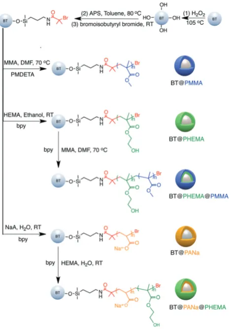
The main features of the ‘‘grafting from’’ strategy is to build a shell layerviaanin situpolymerization of monomersviathe initiating sites on the nanoparticle surface.109,112,179 Atom Transfer Radical Polymerization (ATRP) and reversible RAFT methods are usually employed in the ‘‘grafting from’’ strategy process. As shown in Fig. 11, poly(2-hydroxylethyle methacry-late) (PMMA), poly(hydroxyethyl methacrymethacry-late) (PHEMA) and sodium polyacrylate (PANa) were coated on the surfaces of BaTiO3nanoparticles by ATRP method, respectively, and core@
double-shell structured BaTiO3nanoparticles were prepared by
grafting PHEMA-block-PMMA and PANa-block-PHEMA block copolymer using ATRP method. For RAFT method, the process is outlined in Fig. 12. Firstly, the RAFT reagent e.g. 4-cyano-pentanoic acid dithiobenzoate (CPDB) is introduced on the surface of any modified nanoparticles, then the monomer of the modifier polymer initiates in situ polymerization by the RAFT reagent. In this method, the thicknesses of the polymer
Fig. 10 Schematic of processing procedure of PVDF nanocomposite with dopamine modified BaTiO3 nanoparticles and KH550 modified Bi2S3
nanorods. Reprinted from ref. 177, Copyright (2018), with permission from Elsevier.
Open Access Article. Published on 04 July 2019. Downloaded on 8/21/2019 5:12:11 PM.
This article is licensed under a
shell can be tailored by varying the molecular weight of the grafted polymer. Core–shell structured BaTiO3 nanoparticles
with either different shell thickness or different molecular structures were prepared by grafting two types of fluoroalkyl acrylate monomersviaRAFT polymerization. It was shown that
a high energy density and low dielectric loss could be success-fully realized in the nanocomposites. Moreover, the energy storage densities of the P(VDF–HFP)-based nanocomposites could be tailored by adjusting the structure and thickness of the fluoro-polymer shell.86 As an example, nanocomposites
with a thick polymer shell were prepared using fluoro-alkyl acrylate monomers with short side groups, which exhibited a high breakdown field and enhanced energy storage capability in comparison with the pure P(VDF–HFP); for example 6.23 J cm3 for a nanocomposite with 50% BaTiO3–PTFEA2 and 4.10 J cm3
for P(VDF–HFP).
Recently, the reduction of nanoparticle agglomeration and improving their dispersibility in nanocomposites via strong bonding,48,180–191has led to the development of a viable route to prepare organic–inorganic nanocomposites composed of monodisperse ferroelectric nanoparticles, which were directly bonded with polymers utilizing rationally designed amphiphilic star-like diblock copolymer as nanoreactors. Star-like diblock copolymers, such as poly(acrylic acid)-block-poly(vinylidene fluoride) (PAA-b-PVDF), were prepared by sequential ATRP and copper-catalysed azide–alkyne cyclo additions. The precursors were selectively incorporated into the space occupied by the inner PAA blocks and converted into BaTiO3 nanoparticles directly
and were stably capped with PVDF chains, as shown in Fig. 13. The PVDF-capped BaTiO3 nanoparticles were highly uniform
and after hot-pressing the chemically synthesized PVDF-capped BaTiO3 nanoparticles, homogeneous PVDF/BaTiO3
nanocom-posites were fabricated. It was found that the PVDF/BaTiO3
nanocomposite filled with 84.7 wt% nanoparticles (B16 nm) possessed a high relative permittivity oferB85 (at 2 MHz) and
dielectric loss of B0.028. In comparison, pristine PVDF exhibits a relative permittivity oferB10 and dielectric loss of
B0.16. This improvement can be attributed to the large inter-facial areas and strong interinter-facial interactions in the PVDF/ BaTiO3 nanocomposite which promote interfacial exchange
coupling through a dipolar interface layer, thereby leading to the enhanced polarization, improved relative permittivity and reduced dielectric loss.
Fig. 11 Synthesis of functionalized BaTiO3nanoparticles using a ‘‘grafting
[image:12.595.52.287.48.382.2]from’’ strategy. Reprinted with permission from ref. 109. Copyright (2016) American Chemical Society.
Fig. 12 Synthesis of functionalized BaTiO3nanoparticles using ‘‘grafting from’’ strategy. Reprinted figure with permission from ref. 179. Copyright (2014)
American Chemical Society.
Open Access Article. Published on 04 July 2019. Downloaded on 8/21/2019 5:12:11 PM.
This article is licensed under a
3.2 Tailoring the interfacial thickness by organic rigid liquid crystalline polymers
The interfacial region can be considered as a shell of a certain thickness on the nanoparticle surface, as shown in Fig. 14a.36 The volume fraction of the interfacial region (finterface) of a
spherical nanocomposite filler can be calculated by eqn (2):
finterface¼fparticle 1þ
2t d
3
1
" #
(2)
wheret is the interfacial thickness, d is the diameter of the nanoparticle and fparticle is the volume fraction of the filler.
As shown in Fig. 14b, the magnitude offinterfacewill be
signifi-cantly increased with an increase of interfacial layer thickness and a decrease of nanoparticle diameter. Therefore, the inter-faces and interfacial layer thickness between the ceramic filler and polymer matrix is a dominant factor that influences the effective electric properties of nano-scale based composites
and ultimately their properties and performance in storage applications.192However, control of the interfacial layer thick-ness and understanding the detailed effects of interfacial regions on the dielectric properties and energy storage density of the nanocomposites continues to be a challenge.
As discussed in Section 3.1, many of the polymers employed as interfacial modifiers are flexible organics, which generally have a random walk or Gaussian coil chain shape due to the flexibility of their molecular backbone.58,193,194The interfacial thickness tends to be proportional to the molecular weight of polymer, however, it cannot be precisely calculated via
the average degree of polymerization of the polymer. Rigid chain structures,i.e.p-conjugation along the polymer backbone (semiconducting polymers), helical secondary structures (biomolecules), aromatic groups (aramid and aromatic poly-ester high-performance resins) or mesogen-jacketed liquid crystalline polymers, all lead to the adoption of extended and rigid chain conformations. Among them, the mesogen-jacketed liquid crystalline polymers can be synthesized by a living radical polymerization and the polymer-chain length can be tailored by controlling the degree of polymerization, thereby resulting in an interfacial modified thickness that can be accurately controlled by design of the degree of polymerization of the mesogen-jacketed liquid crystalline polymers; as shown in Fig. 15.193,195
Kuang and Xieet al.196successfully grafted a liquid crystal-line polymer with azobenzene mesogens as the side chain to
Fig. 14 (a) Schematic of the ceramic/polymer interface structure in a nanocomposite. (b) Volume fraction of interface in the nanocomposites with the diameter of nanoparticles and interface thicknesses. Reproduced with permission from ref. 36. Copyright 2018, John Wiley and Sons.
Fig. 13 Synthetic route to amphiphilic 21-arm, star-like PAA-b-PVDF diblock copolymer and subsequent conversion into PVDF-capped BaTiO3
nanoparticles and PVDF/BaTiO3 nanocomposites. Reproduced from
ref. 48 with permission from the Royal Society of Chemistry.
Fig. 15 Schematic of a rod-like mesogen-jacketed liquid crystalline poly-mers (MJLCP). Reproduced from ref. 193 with permission from the Royal Society of Chemistry.
Open Access Article. Published on 04 July 2019. Downloaded on 8/21/2019 5:12:11 PM.
This article is licensed under a
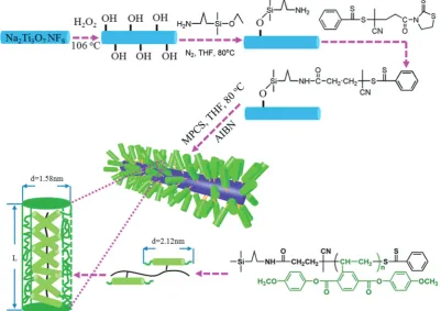
golden nanoparticles by the two-phase Brust–Schiffrin method. In addition, Luoet al.125utilized a liquid-crystalline polymer, PMPCS to design and tailor the interfacial region, and focused on the effects of the interfacial layer thickness between a Na2Ti3O7 nanofiber filler and the polymer matrix on the
performance of the nanocomposites, as shown in Fig. 16. PMPCS is a rigid polymer with crowded, and bulky side groups connected with the main chain through a short spacer or with a single covalent bond.197,198These interesting features lead to the PMPCS forming a rigid polymer structure, and when the molecular weight of the PMPCS is greater than 104, the main chain is constrained to form a straight conformation. The size of the straight conformation unit can be calculated by eqn (3):199,200
Lrod= 0.154 (nm)2Nrodsin 521E0.24Nrod(nm) (3)
As shown in Fig. 14, a mace-like structure is formed, including ‘‘sticks’’ that originate from the Na2Ti3O7 nanofibres and
‘‘spikes’’ that originate from the rigid PMPCS columnar units. The size of the mace-like structure could be tailored by the length and diameter of Na2Ti3O7 nanofibres, as well as the
length of PMPCS column units. The PMPCS column units were grafted onto the Na2Ti3O7nanofibre surfaceviaa RAFTin situ
polymerization method, and the length of the PMPCS column units was determined by eqn (3). It is of interest to note that the prepared Na2Ti3O7@PMPCS/P(VDF–HFP) nanocomposites
showed an increased relative permittivity from er B 10.7 to erB69.6 at 1 kHz with a change in thicknesses from 9 nm to
25 nm of the PMPCS shell. This approach provides a route to modulate the properties of the dielectric nanocomposites, in addition to the loading level and ceramic filler type. The authors proposed that the PMPCS layer between the Na2Ti3O7
nanofibers and P(VDF–HFP) matrix acted as insulating isola-tion layer, which prevented the movement of free electrons, and the cumulative free electrons on the interface with the increase in PMPCS layer thickness led to a strong polarization. As discussed in Section 2.2, a fluoro-polymer is an improved modifier to engineer the surface of ceramic fillers compared with hydrocarbon modifier.
A novel liquid-crystalline polymer PTFMPCS was also inves-tigated by introducing fluoro-atoms into the PMPCS to engineer the surfaces of BaTiO3 nanoparticles.107,201,202 As a result, a
significantly improved energy density was achieved by accurate interfacial control using this fluoro-polymer in a polymer nanocomposite. Subsequently, a series of fluoro-liquid-crystalline polymers with three to seven fluoro-atoms were prepared, which were used to engineer the surface of BaTiO3
platelets and nanoparticles and modulate the performance of the composites.
3.3 Formation of a controllable inorganic ceramic shell layer
[image:14.595.98.500.53.336.2]A number of routes have been used for the preparation of core–shell structures with an inorganic ceramic shell layer of moderate to high relative permittivity to mitigate electric field concentrations at the interface between the filler and matrix.203 The methods used included sol–gel,87 hydrothermal,204
Fig. 16 Modulation of the interfacial layer thickness on Na2Ti3O7nanofibers by rigid polymer PMPCS. Reprinted with permission from ref. 125. Copyright
(2017) American Chemical Society.
Open Access Article. Published on 04 July 2019. Downloaded on 8/21/2019 5:12:11 PM.
This article is licensed under a
hydrolysis reaction,205coaxial electrospinning,206CVD,153and the Sto¨ber method.95 Coaxial electrospinning is a method
recently employed; firstly, a homogeneous precursor solution with a designed molar ratio of the raw target nanofibers was prepared by a solution method.207–210Secondly, the viscosity of
the solution is modulated using polymers, such as poly(vinyl pyrrolidone). Thirdly, the solution is transferred to the syringe of the electrospinning instrument and an appropriate electric field is applied. Finally, the core–shell structured ceramic nanofibers are obtained after an annealing treatment.
Although efforts on preparing core–shell structured fillers with different ceramic shell layers have been made to improve the dielectric and energy storage performance, the effects of ceramic shell layer thickness on the performance of polymer based dielectric nanocomposites is less well explored. Huang
et al.142prepared BaTiO3nanowires encapsulated by TiO2shells
of variable thickness by a kinetically-controlled coating method, as shown in Fig. 17. Two kinds of materials with shell layer thickness dimensions of 50 and 110 nm were obtained by tailoring the tetrabutyl orthotitanate content. The performance of the P(VDF–HFP) polymer nanocomposites with BaTiO3@TiO2 and bare BaTiO3 nanowires were
investi-gated. The results showed that the nanocomposites with BaTiO3@TiO2nanofibers achieved significantly improved
per-formance, including higher breakdown strength and energy storage density due to the more uniform electric field distribu-tion and enhanced polarizadistribu-tion in the nanocomposites by the moderate TiO2 buffer layer compared with nanocomposites
containing only uncoated BaTiO3 nanofibers. For example,
a high energy density of 9.53 J cm3 at 440 kV mm1 was obtained for nanocomposites with core–shell structured nano-wires compared to a lower energy density of 5.60 J cm3 at 360 kV mm1for nanocomposites with 5 wt% uncoated fibers.
It is of interest to note that the energy storage density of nanocomposites can be modulated by the TiO2shell thickness.
To reveal how the thickness of the TiO2buffer layer can affect
the properties of the composites, Hu et al.211 prepared
BaTiO3@TiO2nanoparticles with a modulated TiO2shell layer
thickness from 0–10 nm. The core–shell structured nano-particles were prepared via a surface coating approach in solution and, following heat treatment, the thickness of the TiO2shell layer could be tailored by modulating the amount of
the titanate coupling agent employed in the preparation pro-cess. The core–shell fillers were incorporated into a PVDF polymer matrix and used for energy storage applications where the dielectric properties, breakdown strength, and energy storage performance of the nanocomposites were strongly related to the thickness of the TiO2shell layer. Nanocomposites
with a TiO2shell layer thickness of 1–3 nm achieved the highest
relative permittivity and breakdown strength compared with the nanocomposites with other TiO2shell layer thickness. The
authors proposed that the introduction of a TiO2shell layer on
the surface of the BaTiO3nanoparticle induced a two-charged
interface and therefore more electronic charge was captured in the interfacial region to enhance interfacial polarization.
Recently, TiO2 nanowires with multiple shells including
carbon and SiO2 layers have been prepared.153 The detailed
synthesis procedure is shown in Fig. 18. As shown, TiO2
nanowires was synthesized by a hydrothermal and calcination method using a raw material of TiO2 nanoparticles, and the
carbon layer was formed on the surface of TiO2nanowires using
a CVD treatment; the outer shell SiO2layer was formed by a
sol–gel synthesis method. The composite with TiO2@C
[image:15.595.68.546.460.693.2]nano-wires showed the typical characteristics of a composite contain-ing conductive fillers, where the permittivity and dielectric loss sharply increased with an increase of TiO2@C nanowire
Fig. 17 Preparation process of BaTiO3@TiO2nanowires by a kinetics-controlled coating method. Reproduced from ref. 142 with permission from the
Royal Society of Chemistry.
Open Access Article. Published on 04 July 2019. Downloaded on 8/21/2019 5:12:11 PM.
This article is licensed under a
loading level, see Fig. 18d and e. The percolation response disappeared when the TiO2@C nanowires were coated with an
insulating SiO2layer. As a result, the composites with 30 wt%
TiO2@C@SiO2 nanowires achieved an enhanced permittivity
of er B 41 and suppressed dielectric loss of 0.05 at 1 kHz,
which were superior to the composites containing only TiO2
nanowires.
3.4 Characterization of interfaces in polymer nanocomposites
It is well-known that the interfacial region between the nano-particles and the polymer matrix plays an important role in the electric polarization, mechanical, thermal, and optical proper-ties of nanocomposites. However, it remains a challenge to characterize the interfacial region and its electric properties since the interfacial region cannot be isolated from nanocom-posites based on the existing characterization methods, such as dipolar polarization, space charge density and electric field distribution. At present, there are two important methods to study the interfacial region: indirect analysis techniques (theoretical simulation based on experiment results) and direct analysis techniques. For the former, the interphase bonding, interphase density, and thickness can be quantified using Fourier transform infrared spectroscopy (FTIR), transmission electron microscopy (TEM)/thermal gravimetric analysis (TGA). However, FTIR is applicable only to metal–polymer composites in which the interfacial interactions generate considerable changes in the infrared spectrum of the polymer arising from bonding between the two moieties at the interface.212Using the data gleaned from TGA/TEM or FTIR and subsequent analysis, the interphase density and thickness could be calculatedviathe number of anchoring points per chain. For the latter, there are
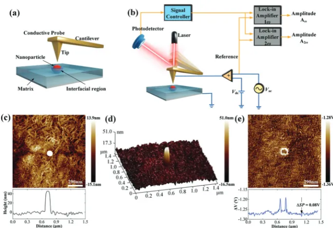
limited reported on efforts to directly observe the interface structure and assess their physical properties. For example, Li and He et al. have recently detected the local polarization properties at the matrix/particle interface in ferroelectric nano-composites via a modified Kelvin Probe Force Microscopy (KPFM) method with nanoscale spatial resolution. In principle, the surface potential of ferroelectric polymers can be influ-enced by dipolar polarization and KPFM can be effective in measuring nanoscale variations in the local surface potential at the interface. Compared with the standard KPFM approach, the main features of the modified KPFM include open-loop control and PeakForce Tapping mode imaging; Fig. 19 shows such a setup. The results indicated that the electric polarization in the matrix/particle interfacial region was higher than the polymer matrix under the application of an electric field.213
4. Interfacial models, polarization
mechanism and simulations
[image:16.595.106.489.49.287.2]We have seen that nano-sized ceramic fillers embedded in a polymer matrix lead to the formation of a large interfacial region area, which plays an important role in determining the properties of the nanocomposites since the interface has a significant impact on the physicochemical properties of materials.214–217 In general, the interfacial region in polymer nanocomposites is characterized as a region that extends from the surface of the nanoparticle, through the modification layer and interfacial polymer layers (with modified chain structures), and finally to the host matrix polymer.36This section reviews
Fig. 18 (a) Schematic of the synthesis of TiO2@C@SiO2nanowires starting with TiO2nanoparticles and TEM images of the core–shell structured (b)
TiO2@C and (c) TiO2@C@SiO2nanowire. Relative permittivity (d) and dielectric loss (e) of PVDF-based nanocomposites loaded with TiO2nanowires,
TiO2@C nanowires, and TiO2@C@SiO2nanowires as a function of filler content. Reprinted from ref. 153, Copyright (2018), with permission from Elsevier.
Open Access Article. Published on 04 July 2019. Downloaded on 8/21/2019 5:12:11 PM.
This article is licensed under a
the interfacial models, polarization mechanisms and simula-tions to examine polymer based nanocomposites.
4.1 Interface models
Usually, ceramic–polymer nanocomposites consist of three regions, the polymer matrix, the ceramic filler and the inter-facial layer. It is a challenge to fully characterize and under-stand the interfacial regions, such as nanoparticle surface states, polymer chain configurations, inorganic/organic com-patibility and local interfacial electrical and dielectric beha-viour. The development of interface models can enable an improved understanding of interface effects on the electrical and dielectric properties of such nanocomposites. According to previous studies,218,219the interface can change the distribu-tion and modistribu-tion of space charges, resulting in improved polarization, and act as scattering points to prolong carrier path length, thereby improving breakdown strength. Moreover, interfaces often serve as traps for charges and can result in regulated local charge mobility and conductivity. In addition, the modified electronic states of interfaces can create traps or change the depth of traps, which is closely related to the space-charge (interfacial) polarization and breakdown behaviour. Interfaces can also induce a change in the polymer molecular structure that initiates from the interfacial region to the matrix (free volume fraction, mobility, crystallinity, and configuration of polymer chains), which affects the dielectric properties of the polymer matrix.
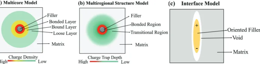
A variety of interface models have been proposed to describe the interfacial interactions in dielectric nanocomposites, the mode of charge transportation and its effect on electrical properties.220–222 Tanaka developed a multi-core model to describe the interactions between the polymer and spherical
[image:17.595.125.467.47.281.2]ceramic nanoparticles.221 In this model, the interfacial layer includes three layers: (i) the bonded layer, (ii) the bound layer and (iii) the loose layer, as seen in Fig. 20a.4The bonded layer is based on polymer chains, which are bonded tightly to both the inorganic filler and the polymer network. The interactions holding these chains in place are electrostatic, covalent, hydro-gen bonding or van der Waals forces. The bound layer is considered to beB1 nm thickness and prevents the formation
Fig. 19 (a) Schematic of the Kelvin Probe Force Microscopy (KPFM) testing process. (b) Schematic of the working principle. (c) Topography signal near an embedded nanoparticle. (d) 3D image of the surface topography near an embedded nanoparticle. (e) TheDVsignal near an embedded nanoparticle. With permission from ref. 213. Copyright 2019, John Wiley and Sons.
Fig. 20 (a) The multi-core model for polymer nanocomposites, (b) charge distribution of a diffuse electrical double layer.
Open Access Article. Published on 04 July 2019. Downloaded on 8/21/2019 5:12:11 PM.
This article is licensed under a
[image:17.595.309.549.445.692.2]