Bell Technologies MPE 386 Computer System
System Guide
Copyright 1987, Bell Technologies All rights reserved.
1. Things You Should Know
2. Your MPE Uses AT Standards • • 2.1 The Modular AT Architecture 2.2 System Board • • • 2.3 Chassis and Cover. •
CONTENTS
2.4 Power Supply • • • • • • 2.5 Keyboard • • • • • • • • • 2.6 Mathematics Co-Processor •
2.7 Expansion Cards • • •
2.8 Hard Disks, Roppy Disk Drives, and Tapes • 2.9 Monitors • •
2.10 Terminals 2.11 Printers
2.12 System Features 2.13 System Specifications 3. Unpacking • • • • • • •
3.1 Shipping Damage • • 3.2 Save All Packing Materials 3.3 Static Precautions • • 3.4 Hard Disk Handling 3.5 Handling MPE Systems 4. Internal Options Installation •
4.1 Cover Removal • • • 4.2 Replacing the Cover . 4.3 System Board Configuration
4.3.1 System Board Default Settings 27 4.3.2 DIP Switch Array Settings 27 4.3.3 Configuring For Color Displays 27 4.3.4 Installation of 80387 Co-Processor 27 4.3.5 Installing the Second Serial Port 28 4.4 Installing Adaptor Cards • • • • • • • 4.5 Installing Disks, Tapes, and Other Devices 5. External Options Installation
5.1 Site Selection and Preparation 5.2 Getting Ready For Operation 6. System Checklist • • • 7. Power On Self Test (POST) •
7.1 The Boot Process 8. The SETUP Program • • •
8.1 Date and Time • • • 8.2 Floppy Diskette Drives 8.3 Fixed Disks • • • •
8.4 Base Memory and Extended Memory •
8.5 Video Display Adaptor • • • • • • • •
9. MPE System Board Reference. • • 9.1 Introduction. • • • • • • • 9.2 Installation and Removal of Chips •
9.3 System Board Features • • • • • • • • 9.3.1 80386 Processor Socket 53
9.3.2 80387 Math Co-Processor Socket 53 9.3.2.1 Intel Erratum 21 Management 54 9.3.3 Timers 54
9.3.4 System Memory 54
9.3.4.1 Expansion Memory Boards 55 9.3.4.2 System ROM 56
9.3.5 ROM BIOS Supplied 56 9.3.6 Expansion Card Slots 57
9.3.6.1
XT
Slots 58 9.3.6.2 AT Slots 59 9.3.6.3 32 Bit Slots 60 9.3.7 I/O Address Map 62 9.3.8 Interrupt Controllers 63 9.3.9 DMA Controllers 649.3.10 Oock/Calendarand CMOS RAM 65 9.4 DIP Switch Options • • • • • • • 9.5 System Board Connectors and Pinouts
9.5.1 Battery Connection for CMOS RAM 68
9.5.2 Keylock Connector and LED Power Source 69 9.5.3 Speaker Interface 70
9.5.4 Turbo Indicator Output 71 9.5.5 Keyboard Connector 72 9.5.6 Main Power Connector 73 9.5.7 Power Requirements 74 9.5.8 Parallel Port Connector 75 9.5.9 Serial Port Connectors 76 9.5.10 Reset Switch 76
9.6 System Board Jumpers • • 9.6.1 Video Select - W8 77
9.6.2 CPU Speed Control Source - W10 78 9.6.3 32 Bit Memory Wait State Selection - W2 79
9.6.4 16 Bit and 8 Bit Memory Wait State Selection - W3 and W4 80 9.6.5 Manufacturing Test Jumper - W20 81
9.7 Quick Reference Guide To Jumpers and Connectors. 10. Maintenance
ii
UST OF FIGURES
Figure 1. Front Panel and Key Lock •
Figure 2. Cover Mounting Screws
Figure 3. Removing the Cover
Figure 4. Locations of Items on System Board
Figure 5. Remove the Expansion Slot Cover
Figure 6. Installing an Option Card
Figure 7. Card Edge Supporting Slide
Figure 8. Press Firmly on the Option Card
Figure 9. Replace the Bracket Screw
Figure 10. Installing a Peripheral Device
Figure 11. Cable Connections to Peripheral Device
Figure 12. Set the Voltage Selector Switch • • • • •
Figure 13. Connect Monitor Cables
Figure 14. Connect Keyboard • •
Figure 15. Locations of Items on System Board
21
. . . .
22.
. . .
.
22 2429
30
31
32
33
35
36
39
40
41
UST OF TABLES
TABLE 1. Power Supply Input Requirements • TABLE 2. Power Supply Output Specifications TABLE 3. Power Supply Output Sense Levels • TABLE 4. MPE System Dimensions • • • • TABLE 5. MPE System Environmental Requirements TABLE 6. Quick Reference to Jumpers • • • TABLE 7. DIP Switch Array Default Settings TABLE 8. Quick Reference to Connectors • • TABLE
9.
Bell Hard Disk TypesTABLE 10. Extended Memory Values for SETUP TABLE 11. System Memory Utilization
TABLE 12. PC XT Connector Pinout TABLE 13. PC AT Connector Pinout
TABLE 14. 32 Bit Connector Pinout • • • • TABLE 15. System I/O Memory Map •
TABLE 16. Interrupt Line Usage TABLE 17. DMA Channels
TABLE 18. Clock/calendar and CMOS RAM Memory Mapping TABLE 19. Ten Position DIP Switch Array - Location SWl TABLE 20. DIP Switch Array Default Settings
TABLE 21. Battery Connection - Location W6 TABLE 22. Keylock Connector - Location Wll • TABLE 23. Speaker Connector - Location W7
TABLE 24. Turbo LED Connector - Location W12 • • TABLE 25. Keyboard Connector - Location J6 • TABLE 26. Main Power Connector - Location J2 TABLE 27. Power Requirements of 4MB System Board TABLE 28. Parallel Port Connector - Location J12 • • • TABLE 29. Serial Port Connectors· Locations Jl1 and Jl0 TABLE 30. Video Select Jumper - Location W8 •
TABLE 31. Video Select Jumper - Location Wl0
TABLE 32. 32 Bit Memory Wait State Selection - Location W2 • TABLE 33. 16 Bit Memory Wait State Selection - Location W3 TABLE 34. 8 Bit Memory Wait State Selection - Location W4 TABLE 35. Manufacturing Test Jumper - Location W20 TABLE 36. Quick Reference to Jumpers • • • TABLE 37. Quick Reference to Connectors • TABLE 38. DIP Switch Array Default Settings
79
80
80
8182
83
1. Things You Should Know
This section introduces you to the MPE 386 Computer System rMPEN
) . It tells how to use this manual for installation and operation. It provides you with important cautionary notices that must always be observed.
This manual describes the MPE 386 Model 400, which Includes 4MB of memory on the system board. For less than 4MB of memory the Model 400 Is often shipped with no memory on the' system board and 1 or 2 MB of RAM Installed In a 32 bit expansion memory card. Except for memory size, such 1 or 2 MB configurations are identical to those described here.
CAUTION I Your MPE uses electricity and contains dangerous levels of electricity inside the chassis during operation. Always disconnect the power cord from both the MPE and the wall socket before opening the chassis for any type of service or configuration. Always make sure your system is turned OFF before commencing any type of work on it. The inside of the MPE power supply should be serviced only by factory-trained technicians. Dangerous amounts of electricity are present inside the power supply even after it has been turned OFF and disconnected from the power cord.
CAUTION I Incorrect configuration, assembly, or installation of your system can cause permanent damage to system components. Do NOT plug in your system or turn power ON without first consulting the System Checklist section of this manual. Consult the System Checklist even if you are experienced with AT standard machines.
Your MPE system must be correctly configured before operation. Configuration involves several steps:
1) Unpacking.
2) Installation or verification of internal options such as video cards, disks, tape drives and so on.
3) Attachment of external options such as keyboard, monitor, printer, and terminals.
4) Setting up the system's internal configuration memory using the SETUP diskette provided.
5) loading the operating system and desired software and commencing operations.
This manual covers the first four steps as well as general system hardware related operations. Consult your operating systems manual for information on your operating systems software.
You may have received your MPE already setup by your dealer or systems vendor. If so, after Unpacking you may proceed directly to the External Options Installation chapter.
2. Your MPE Uses AT Standards
We designed the MPE to take advantage
of
the largest Industry standard in the world for computer: IBM's -AT architecture machines. Tens of thousands of vendors world wide support this architecture. Those computer users who use the AT standard enjoy by far the best performance, the best price, and the best quality of any computer system.The basic parameters of the AT standard such as system board size, expansion slot placement and pinout, power supply form factor, chassis form factor, bus signals and CPU architecture all derive from IBM's original 16 bit PC AT design, which
used the Intel 80286 processor. The AT
architecture is so powerful, however, that certain aspects of It such as the 16 Megabyte (MB) memory capacity are underutilized with 16 bit processors and are much better matched to the world of 32 bit computing.Your MPE extends the AT architecture to the world of 32 bit supermini computing. The 32 bit 80386 processor employed in the MPE provides an extremely sophisticated and powerful 32 bit CPU. In addition to its 32 bit architecture, the 80386 provides dedicated hardware compatibility with earlier Intel processors such as the 80286, 8086, and 8088. This enables the 80386 to run DOS and other software written for 16 bit PC AT's and 8 bit PC's as well as 32 bit software like UNIX derived from the world of
VAX
and other 32 bit minicomputers.Unlike other AT standard machines, the MPE was designed explicitly for superior operation in UNIX and Xenix as well as with DOS. All components used in the MPE are selected for certified use with UNIX and Xenix. This includes the special selection of full "EE" series 32-bit 80386 chips and Intel Erratum 21 suppression with proprietary Bell Technologies circuitry. Bell Technologies supplied the 80386 AT compatible machines on which UNIX for the 80386 was developed by Intel, AT&T, and Interactive Systems. Every bit of that experience was used to make the MPE a superior UNIX and Xenix engine without sacrificing total AT standards compatibility.
True AT compatibility revolves about three factors: mechanical compatibility, system architecture compatiblity, and firmware/software compatibility.
Your MPE chassis provides perfect mechanical compatibility with the AT standard. All dimensions match the standard perfectly. The MPE chassis has been manufactured from industrial grade materials to provide a far more rigid and durable frame than is common in AT compatibles.
All system board mechanical details match the AT standard as well. Placement and size of expansion bus, keyboad connectors, mounting holes, and overall size and shape of the Printed Circuit Board (PCB) match the AT standard exactly.
The system board architecture provides complete compatiblity with the AT standard at the system level. All Direct Memory Access (DMA) channels, Interrupt vectors, memory mapped ijolocations and other factors match the AT standard perfectly. See the reference section on the system board for more information. Extension to 32-bit architecture has been accomplished without compromising either AT compatibility or 32-blt performance.
Perhaps the largest component of AT standard compatiblity in actual use is the performance of the Read Only Memory (ROM) firmware known as the Basic Input Output System (BIOS). Bell Technologies ships only the industry standard BIOS firmware, either Phoenix or Award. This manual describes the Phoenix BIOS.
2.1 The Modular AT Architecture
One of the nicest things about the AT standard is Its modularity. System components may be interchanged within a large family of parts from thousands of different vendors. All standard parts conform to size, electrical interface, and systems compatibility. By using standard modules, you or your systems vendor can configure your MPE to perform any function known to the computing worid. The primary classes of standard AT parts are as follows:
2.2 System Board
The MPE System Board (also called the ·motherboard·) is the central part of your MPE. It prOVides a complete computer system on a single board. The expansion slots it provides can host any standard AT or PC option card to provide additional capabilities. The MPE System Board Is a Bell Technologies 2116-4 four Megabyte (MB) system board manufactured in the United States. Series 2116 system boards may be Inserted into any standard AT chassis. Certain accessories are directly related to the function of the system board:
• Lithium Battery - The system board contains a small amount of Random Access Memory (RAM) which is powered by this battery. Because of the battery power supply this small area
of
RAM "remembers· data stored into it even after the system power switch is turned OFF. This area of RAM is used to store system configuration information known as ·setup· data.• Audio Speaker - AT standard machines use a small audio speaker to generate sound. This is useful to create ·beeps· and other sounds that communicate the status of hardware or software.
• Front Panel Switches and Signals - The front panel reports important system status and provides two control switches. Status is reported through Light Emitting Diodes (LEOs) for power ON and hard disk activity. The switches are used to reset the system and to lock or unlock the chassis and keyboard functioning.
• Parallel and Serial Port Cables - Your MPE provides two serial ports and a parallel port. The cables and connectors for these attach directly to the system board.
2.3 Chassis and Cover
The chassis provides a metal frame on which system components are mounted. The MPE chassis supports the system board and power supply. In addition, it provides mounting points for accessories directly related to the system board (Lithium battery, speaker, front panel, serial and parallel cables). One OB25 style parallel port connector mounting point and one OB9 style serial port mounting point is also provided.
accept any AT standard system board and power supply.
2.4 Power Supply
The MPE utilizes an AT form factor standard 220 watt power supply with output connectors for the system board and four peripheral devices. The power supply may be switched from 115 to 230 volts for use wortdwide. It automatically accomodates 50 or 60 HZ line frequencies. The power supply provides an auxiliary switched AC power outlet for use with a monitor or other accessory. The MPE power supply Incorporates a voltage sense capability that Is used to shut the supply down in case of shorts or excess current conditions. In addition, It provides a power good signal to the system board which holds the system In reset on startup until all voltages reach operating levels. The MPE power supply should not be replaced except with an equivalent grade AT standard supply providing a minimum of 220 watts output.
2.5 Keyboard
The MPE system board's keyboard connector and related circuitry accept any AT standard keyboard. Shipments from Bell Technologies provide the Enhanced AT standard keyboard with 101 keys and a separate cursor key pad. You may also use the basic AT standard keyboard which does not provide a separate cursor key pad. Many other AT keyboard standard Interface accessories will also attach to the MPE keyboard connector, such as "wedge· style bar code and magnetic card readers.
2.6 MathematiCS Co-Processor
The MPE system board Includes a socket for Insertion of an Intel 80387 mathematics co-processor Chip. The 80387 provides floating point arithmetic capability hundreds of times faster than that possible using software floating point procedures in the main 80386 processor. The 80387 will provide faster floating point than that found on some $200,000 32-bit ·superminis. "
On a technical note, your MPE system board has been designed to minimize the impact of Intel Erratum 21, a technical issue that affects all 80386 chips manufactured to date when used with 80387 mathematics co-processors. Unlike most other AT standard machines, the MPE will run essentially error-free even software that has not been written with Erratum 21 in mind. For total elimination of Erratum 21 under all circumstances the Bell Technologies Math Adaptor may be inserted in your system as well. See the reference section on the system board for more details.
2.7 Expansion Cards
The basic "single board computer" provided by the MPE system board is of limited use without peripherals. In the AT standard peripheral functions such as video display monitors, floppy disks and hard disks are provided by a combination of circuit cards which plug into the system board's expansion slots and peripherals which plug into the expansion circuit cards. Some peripherals such as floppy disks are mounted inside the MPE chassis while others such as video monitors and terminals are placed outside. Some peripherals such as tape backup units or modems may be procured in either internal or external versions.
In the AT standard, expansion cards may be either "8-bit· or "XT" cards (referring to their origin in IBM's PC and PC XT line
of computers) or they may be "l6-bit" or "AT" cards (referring to
cards developed for AT class machines and not intended to be backwards compatible with theXT class as well). Because the AT architecture provides compatiblity with the eariier class of XT machines. XT cards may be used In AT's as well.
The MPE system provides six expansion slots which are combination XT JAT connectors. In addition. it provides two expansion slots which are combination XT j32-bit connectors. The 32-bit connectors provide full 32-bit bandwith for extremely high performance expansion cards used with the MPE.
"xr
style cards have a shorter card edge connector and plug into only half of the expansion slot connectors provided on the system board. the half which Is closest to the back of the system board.An XT card may be plugged into any MPE expansion slot.
"Ar style cards have two card edge connectors. These may be inserted into any of the six XT JAT slots provided in the MPE. Do not insert AT cards Into the XT /32-bit MPE slots. The 32-bit expansion slots are reserved for use by Bell Technologies 32-bit cards and other cards. approved by Bell Technologies. specifically designed for use in the MPE.
If the additional capabilities provided by the extra AT bus slot are not required for functionality. many expansion card vendors will implement their cards using the XT slot only in order to be able to sell the card to XT users as well as AT users. For certain types of cards (monochrome video. for example) there is no performance penalty associated with using an XT style card instead of an AT style card. In other cases maximum performance (hard disk controllers. for example) demands the use of the full AT bus.
Expansion cards generally come in two sizes: full size and half sized. Full size cards extend completely from the rear of the MPE chassis to the front. "Half cards· extend from the rear only part of the way to the front of the chassis. Many half cards do not extend beyond the bus connectors. There is no functional difference between full sized cards and half cards. Since some AT or PC standard machines have restricted room inside the chassis. expansion card vendors will often try to fit their circuitry onto a half card in order to be able to sell to users of such restricted space machines. Full-sized cards may be used in all MPE expansion bus slots. Some older style XT cards use a "drop down" to extend the amount of space on the card available for circuitry. Such cards violate the AT standard and cannot be plugged into XT JAT connectors. The MPE does not support the use of such cards.
For immediate functionality. the MPE is almost always equipped with a video card and monitor and with a disk controller card and disk drives. These cards and others are covered in the following. synopsis of common expansion cards.
using workstation graphics cards In the MPE (see below).
Use extreme care when attaching display cards to monitors: do not connect color monitors to monochrome cards and vice versa. Doing so can damage both the card and the monitor.
• Disk Controller Cards - In the AT standard, a single AT style card Is used to control hard disk and floppy disk drives. A single AT disk controller can control up to two hard disks and up to two floppy disks. Most software that runs on AT standard machines expects to see a disk controller card which is architecturally equivalent to the "'NO- style controller utilized by IBM. Bell Techologies utilizes only "'NO" compatible controllers in Its entire line of disk controllers. There are four standard Bell Technologies controllers: ST506-MFM, ST506-MFM Cache, ST506-RLL, and ESDI. These controllers provide varying levels of disk capacity and performance with varying levels,
of course, of cost. The floppy disk Interface circuitry on all of these controllers Is
equivalent and exactly compatible with the AT fWD standard.• Memory expansion Cards - Your MPE features four MB
of
high speed, 32-bit Random Access Memory (RAM) on the system board. Additional 32-bit high speed memory may be added by installing Bell Technologies 1, 2, 4, or 8 MB 32-blt RAM cards in the XT /32-bit expansion slots. 1 or 2 MB MPE systems may be configured by installing no RAM chips on the system board and Installing a single 32 bit RAM card equipped with 1 or 2 MB of RAM. If you have such a system, a simple service procedure enables you to add 4MB of additional RAM simply by plugging the required RAM chips into the open sockets on the system board [When adding RAM to a 1 or 2 MB MPE system, you must change a PAL chip on the system board - consult the service procedure for more details]. The MPE can also utilize industry standard AT memory cards inserted In the AT expansion slots; however, performance will be much better when 32-bit memory is used.• Tape Backup Controllers - Bell Technologies provides a wide array of tape backup products for use In UNIX, Xenlx, or ~OS. Two styles of controllers are used: OIC-D2 half cards and OIC-36 full sized cards. Each Is available in both an Internal version (where the tape cable runs from the controller card to a tape mechanism mounted inside the MPE chassis) and an external connector version (where the tape cable runs outside the MPE chassis to a tape mechanism mounted in an external box).
• Basic Serial and Parallel Port Cards - The AT standard provides for two serial ports and two parallel ports that are directly -hooked- into the system architecture. Parallel ports are usually used for printers, and serial ports may be used for any serial device: printers, modems, terminals, or other devices. In earlier days. the two serial and two parallel ports were added to AT standard systems through the use of expansion cards which had one serial port and one parallel port each. The MPE system board includes two serial ports and one parallel port that are identically equivalent to those on the previously optional serial/parallel cards. Since most video cards provide an additional parallel port, the typical base MPE configuration includes two serial ports and two parallel ports. This renders obsolete the use of basic serial/parallel cards.
• Serial Port Expansion Cards - When running UNIX or Xenlx the MPE delivers a multiuser computing solution far superior to typical supermicro multiuser machines. Bell Technologies serial port expansion cards may be used to provide additional serial ports. The Intelligent Channel Controller (ICC) expansion card provides six serial ports
that are controlled by a dedicated 80186 16-blt processor and one-half megabyte of RAM. Four ICCs may be Installed for up to 24 serial ports and 24 users. The HUB6 expansion card provides six serial ports in a non-coprocessor card for lighter duty applications or where costs must be kept low. Up to four HUB6 cards may be installed for up to 24 HUB6 serial ports. ICC and HUB6 cards may be intermixed on the same MPE system.
• Modems - While many modems are Implemented as Internal plug-in cards, we recommend the use of external modems connected to serial ports. Most internal modems appear as a serial port In the system architecture and will require you to disable a serial port on your MPE system board. External modems, on the other hand, do not require you to lose a serial port and may be moved from machine to machine as well.
• Local Area Network Cards - Ethernet and other local area networks are becoming extremely popular for linking together computer systems. A host of networking cards are available for AT standard machines that implement every networking protocol in common use on all popular operating systems. The Bell Technologies Ethernet card provides high performance, low cost Ethernet connectivity in UNIX or DOS. In UNIX, the Bell Technologies Ethernet card supports full RFS, SNAP! and TCP liP.
• Workstation Graphics Cards - High performance workstation graphics can be yours on the MPE with the Bell Techn%gies Blit Express workstation graphics engine card. The Blit provides 1660 x 1200 monochrome graphics resolution on 19" big screen monitors as well as 640 x 480 x 8 bit resolution on color monitors. It runs X Windows, SUN NeWS and most popular UNIX workstation software. When operated on your MPE, the Blit outperforms workstations that cost four or five times as much from other UNIX workstation vendors. Graphics cards from other vendors may be used in the MPE for extremely high resolution and performance color graphics as well.
• Nine-Track Tape Controllers - A variety of nine-track tape controller cards are available for operation in UNIX, Xenix, and DOS. These cards control an external nine-track tape mechanism to allow interchange of nine-track reel-to-reel tapes with mainframes and other large computers.
In addition to the Bell Techn%gies products described above, the MPE will accept AT or XT standard expansion cards from any other vendor as well.
2.8 Hard Disks, Floppy Disk Drives, and Tapes
AT standard machines use mass storage peripherals in 5.25" form-factor. Hard disks, floppy disk drives, and tape mechanisms that are mounted Inside the MPE chassis should all
be this
standard form-factor. 5.25" devices are available in full-height or height sizes. Two half-height devices are exactly the same half-height as a single full-half-height device.on the right hand side of the chassis and two half-height bays in the center of the chassis just behind the front panel.
Since the center two half-height bays are not accessible from the outside once the cover is in place, they are usually used for hard disk or other devices which do not need to be handled during operation. They are usually used for a single full-height hard disk or for two half-height
hard disks mounted one above the other.
Since the right hand device bays may be accessed from the outside with the cover in place, they are usually used for floppy disk drives or tape mechanisms or other devices that need to be handled during operation.
As
shipped from thefactory,
only twoof
the right hand bays are visible through the front cover. The plastic insert in the front cover just below the two visible bays may be removed in order to expose the third, lowest bay as well.A typical MPE configuration would have one floppy drive and one tape unit In the right hand bays with one full-height hard disk unit In the center bays. A system with two hard disks usually comes in two configurations:
1) Two half-height hard disks in the center bays with a floppy and a tape in the right hand bays; or
2) A full-height hard disk in the center bay with another full-height hard disk located in the lower two right-hand device bays underneath a single floppy. In this case the tape drive would be an externally-mounted device.
Another popular configuration is one hard disk in the center bay with two floppies (which could be two different formats) and an internal tape in the right-hand three bays. In this case, the plastic front panel insert would be removed to expose the third right-hand bay.
Every standard MPE will include at least one floppy disk drive, and virtually all will include a hard disk as well. Most units containing hard disks will also include a tape mechanism for data backup and interchange since it is very inconvenient to backup a large hard disk with floppy diskettes.
Hard disks, floppy disk drives, and tape mechanisms come in many different sizes and capacities as follows:
• Floppy Disk Drives - The AT standard floppy drive Is a half-height 5.25" unit that stores 1.2 MB per floppy diskette. This is also called a -high density" floppy since it replaces the eariier XT standard 5.25- floppy diskette drive that could only store 380 to 720 KB
of
data. The lower capacity XT floppy drives are called -low density" units. AT floppy drives can read XT floppies reliably, but cannot reliably format or write low capacity diskettes. Some MPE users, therefore, Install a low capacity half-height floppy drive In addition to the AT floppy drive. Another emerging standard Is 1.44 MB floppy diskette drives that use hard-shell3S
form-factor diskettes. Your MPE firmware and hardware are capable of running any of these standard drives, although some operating systems or other software packages may not be able to handle 3.5"media.
• Hard Disk Drives - The BIOS firmware installed in the MPE supports over 40 different hard disk drives. Bell Technologies ships the MPE with several different hard disks. ranging from 38 to 380 Megabytes capacity. Typical capacities are quoted by Bell
Technologies as unformatted capacity because formatted capacity will differ slightly depending on the operating system used. Bell Technologies uses ST506-MFM, ST506-RLL, and ESDI drives. A typical MPE configured for multiuser installations will utilize the Bell Technologies B130 130 Megabyte hard disk with 23ms average access speed and 7.5 Megabit/second transfer rate. This disk provides approximately 110 MB formatted data storage. With the right controller installed, any 5.25- form-factor drive listed in the BIOS firmware hard disk drive table may be used in the MPE. Other drives will require modification of the BIOS hard disk drive table or special software.
• Tape Backup - Bell Technologies utilizes half-height tape mechanisms using OlC-02 and OlC-36 controller interfaces and OIC-24 standard recording formats. Tapes using quarter inch tape cartridges provide 60 to 150 MB capacities, while mechanisms using compact cassette media provide 60 MB capacity. If possible (and affordable!) it is very convenient to have the tape capacity equal or exceed the capacity of the hard disk being used. Thus the T1251 Bell Technologies tape with 125 MB total storage capacity is a good match for the B130 hard disk with 110 MB formatted capacity.
Mass storage devices are mounted in the MPE chassis by first attaching slide rails to each side of the device. The device is then inserted into the chassis and two fastening screws are attached between the front of the rails and the chassis.
2.9 Monitors
Many supermicro computers do not have console video displays; rather, they use a terminal attached through a serial port as the main system console. In the AT standard architecture, the system console consists of the keyboard attached to the system board and video output consisting of a monitor attached to a video adaptor card plugged into the system board. Even when the MPE is being used as a classic multiuser UNIX machine, the system console continues to be this PC style console.
Monitors must be matched to the video display card being used. MDA and MGA or similar video display adaptor cards utilize IBM compatible monochrome display monitors. Such monitors are available in a variety of phosphor colors, with green and amber being most popular.
CGA, EGA, and PGA cards require specialized color monitors which are incompatible with monochrome display cards. Perhaps the most popular monitors are EGA compatible color monitors. Gaining rapidly in popularity despite their slightly higher cost are multiple synchronization monitors like the NEC Multi-Sync series and similar. Multi-Sync style monitors may be used with CGA, EGA, and PGA cards. Some can even be used with monochrome cards.
Workstation Graphics cards like the Bell Technologies Blit require special purpose monitors. In monochrome mode, the Blit should only be used with Bell Technologies supplied or approved monitors or damage to the Blit and to the monitor will result. In color mode, the Slit may be used with NEC Multi-Sync or compatible monitors.
Since many video display adaptors use similar connectors, It is easy to make a mistake when plugging monitors In. Be careful. Double check connections before turning power on to your system.
2.10 Terminals
Hundreds of terminals types may
be
used with the MPE. Either HUBS or ICC multiport cards allow the addition of any standard RS232 serial terminals for use with the MPE.2.11 Printers
Any IBM compatible printer may
be
used with the MPE's parallel ports. The ports provide a Centronics style interface identically equivalent to that used in the AT standard by IBM. MPE system board serial ports or expansion serial ports provided by ICC or HUB6 cards may be used with any RS232 compatible printer.2.12 System Features
The following are features
of
standard model MPE system boards and complete MPE systems: System Board*
*
*
*
*
*
*
*
*
*
*
*
*
*
*
*
*
*
*
*
*
*
16MHZ Intel 80386 32 Bit Processor
16MHZ 80387 Mathematics Co-Processor Socket 256K to 512K ROM on Board
Phoenix or Award BIOS 4MB RAM memory on-board
8742 Processor-based IBM AT compatible keyboard interface Keylock Interface
Real-Time Clock with Battery-Backup CMOS Setup RAM Sixteen Interrupts
Seven DMA Channels
Two IBM Compatible Serial Ports DB9 Serial Port headers
One IBM Compatible Bidirectional ParaUel Port 8 XT Slots, 6 AT Slots, 2 32-Bit Slots
Audio Speaker Connector
On-Board Configuration DIP Switch Reset Connector
Flexible Wait State Selector Socketed Crystal
*
Up to 16MB 32 Bit memory with standard BIOS.*
4 Gigabyte Physical Memory Addressing. System Features*
*
*
*
*
*
*
*
*
*
*
*
*
*
Industrial Grade Chassis Front Panel Reset Switch
Front Panel Chassis and Keyboard Lock Five half-height Device Bays, Three accessible 220 Watt Power Supply
115 / 230 Volt and 50 /60 HZ Operation. Enhanced and Standard Keyboards
380KB, 720KB, 1.2MB Floppy Diskette Drives 38 to 760MB Total Hard Disk Capacity 60 to 160MB Integrated Tape Backup Full Support for All Video Standards Integrated Workstation Graphics Integrated Local Area Networking
Full compatibility with UNIX, SCO Xenix, Xenix, Interactive 386/ix, Microport, DOS, and OS/2.
2.13 System Specifications
Following are power and environmental specifications for standard model MPE systems. Voltages are In Volts AC or DC as indicated with currents in Amps. Temperatures are in degrees centigrade.
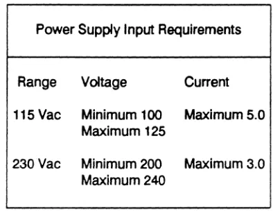
Power Supply Input Requirements
Range Voltage Current 115 Vac Minimum 100 Maximum 5.0
Maximum 125
230Vac Minimum 200 Maximum 3.0 Maximum 240
Note: Power consumption: 220 Watts (Maximum) TABLE 1. Power Supply Input Requirements
Power Supply Output
Nominal Max. Current Regulated To + 5 Vdc 22.6 +5% to-4%
- 5 Vdc 0.4 + 10% to-8%
+ 12 Vdc 8 +5% to-4%
- 12 Vdc 0.4 + 10% to -9%
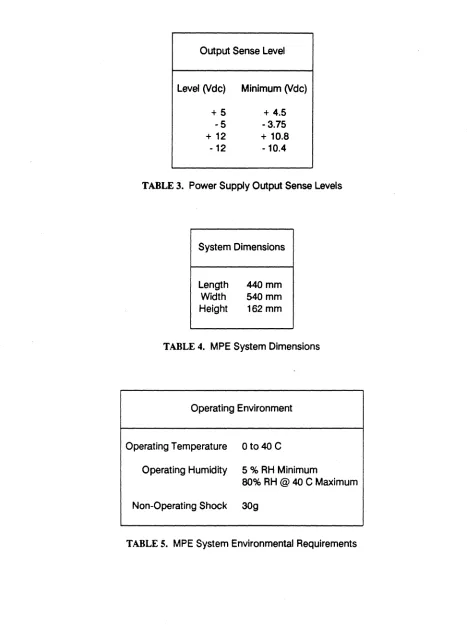
[image:21.612.196.393.169.321.2]Output Sense Level
Level (Vdc) Minimum (Vdc)
+
5
+
4.5
·5
- 3.75
+
12+
10.8 [image:22.612.61.529.56.695.2]-12 ·10.4
TABLE 3. Power Supply Output Sense Levels
System Dimensions
Length Width Height
440mm 540mm 162mm
TABLE 4. MPE System Dimensions
Operating Environment
Operating Temperature 0 to 40 C
Operating Humidity
5
% RH Minimum80% RH @ 40 C Maximum
Non-Operating Shock
30g
TABLE 5. MPE System Environmental Requirements
3. Unpacking
Assembly consists of installation or verification of internal options followed by assembly and installation of external options. Internal options Include video display adapator card, disk controller card, other option cards and mass storage peripherals such as floppy disk drives and hard disks. External assembly includes site selection, attachment of keyboards, video monitors, terminals and other external options.
Do NOT plug the system In or turn power ON until you have reviewed the System Checklist.
MPE systems are shipped in three boxes: the system unit box, the keyboard box, and an accessories box. Most shipments will have all three boxes shipped within an outer container for additional protection during shipment. Monitors are shipped separately. Any peripherals or option cards not installed at the factory will also be shipped in separate boxes.
3.1 Shipping Damage
All Bell Technologies equipment has been thoroughly inspected and carefully packed before leaving the factory. Responsibility for Its safe delivery was assumed by the freight carrier at the time of shipment. Claims for loss or damage to the contents should therefore be made upon the carrier as follows:
Concealed Loss or Damage: Concealed loss or damage means loss or damage which does not become apparent until the equipment has been unpacked. The contents may be damaged in transit due to rough handling even though the carton may not show external damage. When the damage is discovered upon unpacking, make a written request for inspection by the freight carrier's agent within fifteen days of the delivery date. Then file a claim with the carrier since such damage is the carrier's responsibility. By following these instructions carefully, we guarantee our full support of your claims to protect you against loss from concealed damage.
Visible Loss or Damage: Any external evidence of loss or damage must
tie
noted on the freight bill or express receipt and signed by the carrier's agent. Failure to adequately describe such external evidence of loss or damage may result in the carrier refusing to honor a damage claim. The form required to file such a claim will be supplied by the carrier.Carefully remove all components from their packages and inspect each for possible Shipping damage [Do NOT remove any components from their protective anti-static bags until you have read the section in this chapter on static control). If the container or any of the components appears to have received damage during shipping, immediately contact the shipper who delivered your package and request they come out and inspect the damage as described above.
The Bell Technologies warranty does not include damage due to shipping. Therefore, it is very important that any such damage claims be made against the shipper to prevent any further expense on your part.
3.2 Save All Packing Materials
Your MPE ships in specially designed boxes for maximum protection. These boxes are designed to provide protection for sensitive Internal components such as hard disk drives. In addition, other options ship In special protective boxes and packing materials. Do not discard any of these materials as they will
be required should you ever decide to transport your MPE
system to another location. You will also need the Original packing material should you ever need to transport your MPE for warranty service.Remove and save the shipping Insert placed Inside your floppy disk drive. This insert should
be used anytime you transport your MPE even
If you do not pack the system completely. It protects the floppy disk drive recording head from vibration that occurs during transportation when a floppy diskette is not inserted.Remove and save the shipping Insert placed in your cartridge tape mechanism if you ·have a tape unit installed. This insert keeps the tape cartridge mechanism from popping into the load position during transportation and possibly damaging the locking bar.
3.3 Static Precautions
Numerous components In the MPE system and options contain static sensitive components that must be protected against static electricity. AJways observe the following precautions:
Ground YourseH - Touch a metal component connected to ground to discharge any static electricity accumulated on your body before opening any static bag containing components. Touching a metal pan of the chassis usually suffices. When working extensively with static sensitive components (such as repair or large scale chip removal and Insenion) It Is best to work at a statlc-controlled area: a table top that is grounded and sprayed with antistatic solution together with a wrist or ankle static discharge strap attached to ground.
Safe Transport - Carry static sensitive components In anti-static protective bags only. Merely carrying a circuit card across a carpeted floor in wintenime can damage static sensitive components. Components Inside of a closed MPE chassis are safe to transpon as long as you are careful not to touch exposed connectors at the rear of the chassis.
Safe Adaptor Card Handling - Carry circuit cards by their edges only. Do not touch the card edge connector or any other connector.
Safe Peripheral Handling - Carry hard disks, floppy disks, and tape mechanisms only by their metal frames. Do not touch their connectors.
3.4 Hard Disk Handling
Hard disks are the most fragile part
of
modem computing systems. The glass CRT tube, for example, will take far greater shocks than a hard disk without losing Its abHity to function. Hard disks are so fragile because they are built to tolerancesof
millionths of inches. Our drives are built to take G shocksof
40 G's when ruggedized for shipping. They are some of the toughest, If not the toughest drives made today. Nonetheless, you maybe
surprised by how fragUe even a really tough hard disk is.Despite the foam protection surrounding the drive when packed for shipping, a drop of 36 Inches onto hard concrete or other surface wUI exceed 40 G's. Dropping the unprotected drive 5 or 10 Inches onto a hard table top may damage It. Simply moving the drive, even gently like an eggshell, when It is powered up may cause trouble. This ·Inforrnation Is not intended to scare you, but to provide you with procedures that will allow you to move and use your hard disks with confidence. We suggest the following procedures:
• TREAT ANY HARD DISK AS THOUGH IT WERE AN EGGSHELL.
• NEVER move a hard disk or a system containing a hard disk that is powered up. DO NOT move It even one Inch!
• Never allow any hard disk to thump when you set it down on any hard surface. • Never ship any hard disk without packing it in Its original, undamaged shipping
container ..
• When transporting any hard disk or any computer containing a hard disk by vehicle, keep it on a car seat, not in the trunk, unless it is packed in the original shipping container.
3.5 Handling MPE Systems
Treat all MPE systems with care, especially If they contain hard disks. In addition to the handling precautions specified for hard disks observe the following:
• Avoid extremes of hot or cold. If your system is exposed to extremes of heat or cold, allow It to reach standard office temperatures before attempting to operate It. This may take hours If It Is not unpacked. Removing the system cover will decrease the time It takes to reach ambient temperature. Do NOT tum it on to -self heat- its way to ambient temperature.
• Protect it from exposure to moisture. Do not allow your MPE to become wet or to be exposed to dewpoint conditions. Conditions near dewpoint may cause condensation inside the MPE chassis and damage to components.
• Do not jolt or strike your MPE. Hammering on the cover to loosen It for removal is very hard on the floppy disk drive and hard disks.
• Never force connectors. The MPE connectors are designed to operate reliably for decades with no more than firm, gentle pressure to insert or remove attachments. While it may be possible that a connector has failed or is damaged, If you need to use excessive force it is far more likely you are doing something wrong and may be damaging the system.
• Use the shipping inserts with floppy disk drives and tape mechanisms when transporting the system even a small distance. These keep the internal parts of these sophisticated devices safe from possible damage. If you do not have a shipping insert for the floppy handy, you may use a ·scratch" diskette instead for short distances.
4. Internal Options Installation
This section describes how to remove the cover of your MPE system and to configure Internal options.
Read the sections on cover removal, Installing option cards, and on Installing peripherals. These provide a guide to procedures you will follow for specific cards and peripherals.
Before Installing any options, verify the settings of system board shunts and DIP switch. It is easier to verify these when no cards or cables or peripherals are Installed in the system.
Finally, proceed to the sections on configuring and Installing the particular options you wish to use with your MPE system.
If you are confident a" internal options are correctly installed, proceed to External Options Installation.
4.1 Cover Removal
Tools required for cover removal are a medium Phillips screwdriver. Proceed as follows:
1) Turn OFF your system unit power switch.
2) Turn OFF power to all external accesories attached to your system.
3) Make sure the Key Lock on the front panel is In the unlocked position. Turn the Key Lock fully clockwise and remove the key. Keys are usually taped to the rear of the MPE chassis.
Keylock
Power-On Unlocked Locked Indicator Light Position Position
Figure 1. Front Panel and Key Lock
4) Unplug your MPE system's power cord from the back of the MPE. Unplug the power cord from the wall outlet.
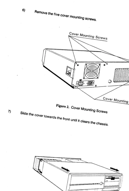
6) Remo.e the
five cover
moUntingSCrews.
COYer Mounting Screws
7) Slide the COVer towards the frOnt UOti/ ij clears the chaSSis. Figure 2. Cover Mounting Screws
[image:30.712.81.512.53.693.2]COYer Mounting Screws
Figure 3. RemOving the Cover
4.2 Replacing the Cover
Replacing the cover Is the reverse of removing It. When replacing the cover, make sure not to snag any cables In the interior of the system with the nut lug protruding from the upper center of the cover's rear edge.
Before closing the top cover, take a moment to check your system for any loose nuts or tools. Verify that all required cables are connected. Check the positions of DIP switches. Record the settings of DIP switches for future reference when setting up software. Verify all expansion cards are firmly screwed down with screws at their attachement brackets. Verify that power cables and ground wires are attached to the peripheral devices. Push the cables down out of the way between the disk device bays and the power supply so that they do not snag the cover.
To install the cover, slide it onto the system chassis with the lower sides of the. cover underneath the metal flanges on the lower sides of the system chassis.
As you slide the cover back, pull the cover up against the metal flanges on the side of the system chassis; this motion allows the upper rear edge of the cover to clear the top of the back panel of the chassis. Reinsert the five cover screws.
4.3 System Board Configuration
The Illustration below identifies major parts of the system board. The W and
J identifiers refer
to jumpers and connectors which are described in the following pages. This section provides a quick reference guide to configuring your MPE system board. The only shunt which you may have to change from Its factory setting iswe
which defines whether a monochrome or color display is the primary display. This is inconveniently located almost underneath the center disk drive bay. For additional information on system board components, see the reference section of this manual.32 BIT
BUS
ROM
DOD
RAM ARRAY
KEYBOARD
iii
IJ2
JilSI0-2
Jl0S10-l
lEI
IJI RESET
1J4 1J3
..
L-======~
TlRIO-SPEAKER-KEYLOCKFigure 4. Locations of Items on System Board
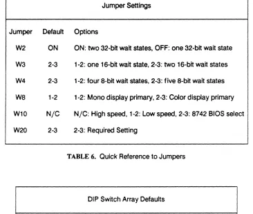
The following tables provide a quick reference guide to the various jumper headers and connectors Installed on your MPE system board. For two pin jumpers. ON means a shunt is installed. and OFF means no connection. N/C means no connection. For jumpers installed parallel to the long axis of the chips. Pin 1 is closest to the front of the board.
Jumper Settings
Jumper Default Options
W2 ON ON: two 32-bit wait states. OFF: one 32-bit wait state
W3 2-3 1-2: one 16-bit wait state. 2-3: two 16-bit wait states
W4 2-3 1-2: four 8-bit wait states. 2-3: five 8-bit wait states
W8 1-2 1-2: Mono display primary. 2-3: Color display primary
W10 N/C N/C: High speed. 1-2: Low speed. 2-3: 8742 BIOS select
[image:33.612.115.481.172.481.2]W20 2-3 2-3: Required Setting
TABLE 6. Quick Reference to Jumpers
DIP Switch Array Defaults
1 2 3 4 5 6 7 8 9 10
OFF ON OFF OFF ON OFF OFF ON OFF ON
Connectors
Connector Definition
W1 Reset switch connection
we
CMOS RAM battery connector W7 8 Ohm Speaker Connector W11 Keylock / Power LED connector W12 Turbo LED connector (use pins 1-2)J2 Main System Power Connector J6 Keyboard Connector
J10 On-board serial port #1 J11 On-board serial port #2 J12 On-board parallel port J13 Not used
J14 Not used
Note: W12 is not connected in the MPE system.
TABLE
8. Quick Reference to Connectors4.3.1 System Board Default Settings
MPE systems are factory configured to run at 16MHZ 1 wait state with an MGA or MDA monochrome display adaptor installed as the primary display adaptor. Serial port 1 and the parallel port are enabled at their standard Interrupt lines. Serial port 2 is located at the standard Interrupt but Is not enabled.
4.3.2 DIP Switch Array Settings
The DIP switch array controls whether the serial ports and parallel port are turned on and which Interrupt lines they use. You should not need to change the setting of the DIP switch array unless you need to Install a peripheral device that uses one of the Interrupt lines assigned to either of the serial ports or to the parallel port.
If you are using a modem or other device that requires access to one of the serial port or parallel port interrupts, you should disable the associated port or move it to a different interrupt line, if available. The reference section of this manual provides detailed information on DIP switch array settings.
4.3.3 Configuring For Color Displays
If you will be using a color display adaptor and color display as your primary display you will need to change the setting of shunt W8 and re-run the SETUP program. This shunt is located in an almost inaccessible place at the rear of the center device bay, almost underneath the bay. It is most easily located and accessed if the center device bay is not occupied by a hard disk drive.
If there is a hard disk drive located in the center device bay, consult the section of this manual on installing peripherals to see how to loosen the front panel and move it out of the way. Disconnect the cables to the hard disk and move them out of the way. It may be helpful to move the floppy disk drive cable out of the way as well. Remove the screws attaching the hard disk drive rails in place and slide the hard disk partly out of the center device bay. This should make it far easier to see and to access shunt
we.
To run a color display as your primary console display, move the shunt at jumper pad
we
so that it connects pins 2 and 3. Pins 2 and 3 are the two pins closest to the rear of the system. Various EGA compatible cards require the system to be set for "Monochrome" as the primary display. If your EGA compatible card does not work withwe
set to Color, try again with W8 set to Monochrome.After setting shunt W8 correctly, reconnect the disk cables, slide the drive back into place and re-insert the holding screws, then replace the front panel assembly. Run SETUP to tell your system you have a color display installed as the primary display.
4.3.4 Installation of 80387 Co-Processor
the 80387's notched off corner to the notched off comer In the 80387 socket. Note that the notched off corner orientation Is different In the 80386 placement on the MPE system board than In the 80387 placement. Insert the 80387 carefully and then press very firmly.
Bell Technologies uses a very expensive machined pin socket as an 80387 socket. This type of socket Is proof against any contact problems caused by oxidation or bad contacts but requires a higher level of Insertion force. To fully Insert the 80387, you will have to bear down with 25 pounds or· more of force. Thus it is Important to have the system board lying flat against solid backing. Do not pound on the 80387: press with a firm and continuous motion with the heel of your hand.
To remove the 80387,
use
a Pin Grid Array large chip puller toolor
with extreme care, a wide flat screwdriver. Pry up the chip only a little bit at a time, working In Increments along each of the edges. You should pry the chip up In such small Increments that it takes two or thre~ times around the four edges to work It free. Take your time.4.3.5 Installing the Second Serial Port
The second serial port is not enabled because this Interrupt location Is used for the HUB6, modem cards, and other accessories. In addition, It Is not accessible from the outside of the system without a cable and slot bracket connector accessory option. If you are not using the HUB6 multiport serial card or other accessory that utilizes the second serial port interrupt, you may wish to Install the second serial port connector and to turn on serial port #2.
Enable serial port #2 by moving the number 2 switch in the DIP switch array to the OFF position (this is backwards from what one might expect It to be).
To install the second serial port connector/bracket accessory, first read through the following section on "Installing Adaptor Cards" to learn how to handle adaptor cards and to install them. After doing so, move the disk controller card over one slot to the left from Its usual rightmost position. This opens up an expansion slot and bracket location immediately adjacent to the lithium battery.
The second serial port connector Is mounted on an expansion card bracket. Install the connector/bracket in the empty bracket slot next to the lithum battery. Plug the header connector at the end of the flat ribbon cable Into connector J11, the serial port connector closest to the lithium battery. Make sure that the dark line on one edge of the flat ribbon cable faces towards the inside of the system chassis, just like on the ribbon cable attached to J10 (the serial port 1 connector).
4.4 Installing Adaptor Cards
Before Installing cards, make sure your system power is OFF and the system is disconnected from the power cord. Review the precautions for protection from static. Remember, ground yourself before opening the option card's antistatic bag and do not touch the card's connectors. Handle only by the card's edges and Insert by holding the top edge only.
1) Locate an unoccupied slot of the
type
required by your card (XT, AT, or 32 bit slot). You may use any unoccupied slot of the type required for your card.2) Remove the screw that holds the expansion slot's cover in place and set the screw aside In a safe place.
Expansion Slot's Cover
I
-LI
~/ave
this screw
I
.
1
Rear panel
[image:37.612.165.464.312.655.2]/
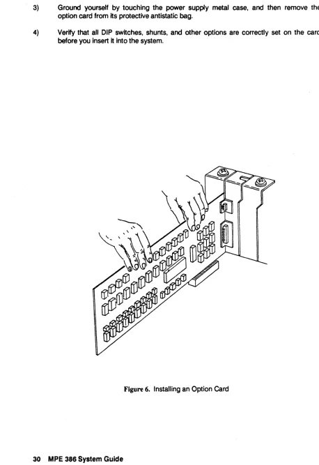
3) Ground yourself by. touching the power supply metal case, and then remove the option card from Its protective antistatic bag.
4) Verify that all DIP switches, shunts, and other options are correctly set on the card before you Insert It into the system.
Figure 6. Installing an Option Card
[image:38.612.51.509.77.744.2]5)
Hold
the
option cardby
lis top
edge
andfirmly press ft
Intothe
expansion
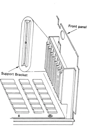
slot whDe making certain the adaptor card edge (for fuIJ-Iength cards) is in the supporting card edge slide at the frontof
the chassis.SUPPort Bracket
[image:39.612.129.440.198.651.2]6) If the card seems ·hung up· at the support bracket at the rear of the MPE chassis, look closely at the bottom of the bracket. The reduced width tang at the bottom of the bracket is intended to insert into a slot cut in the bottom of the MPE chassis 14st below the rectangular expansion slot opening. Occasionally the bottom of the tang may catch on the bottom of the expansion slot opening, or the bottom of the tang (because the lower part of the option card's bracket is bent slightly) may not go into the slot cut for it. In that case, simply bend the tang slightly outwards (the usual case) or inwards so that
It
glides Into the slot for it when the option card is pressed into the expansion bus connectors.7) Press the option card into position to make sure it is inserted all the way into the expansion slot connector.
Figure 8. Press Firmly on the Option Card
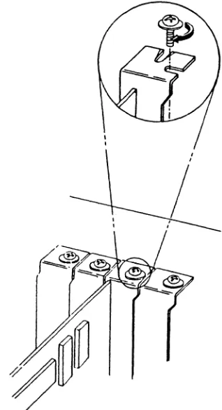
8) Replace the screw removed earlier. This will keep the option card firmly in place.
4.5 Installing Disks, Tapes, and Other Devices
This section provides a general Introduction to Installing devices In the MPE system chassis device bays. It Is applicable to all 5.25- form-factor peripheral devices intended for use in AT standard machines. The Illustrations show installation of a full height hard disk device into the center device bays.
1) Tum system power OFF and disconnect the system power cord from the system and from the wall outlet.
2) Remove the system cover. Ground yourself by touching the metal case of the power supply.
3) Make sure your peripheral device is correctly configured with DIP switch settings, shunts. terminator resistors, etc., before you install it. If you are installing a hard disk, make a copy of the bad block map for later use with your software.
4) Locate the device bay you intend to use. If you are Installing a full height device, you will need to use two half-height bays.
5) If you will be using the center device bay, unscrew the front panel screws and move the front panel out of the way. There is no need to disconnect the front panel wires as they have enough slack in them to allow the front panel to be moved out of the way of the device bays.
6) The center bays may not be covered with a metal cover plate. If not, they will have two or more screws in place which are to be used to hold the peripheral device rails in place after Installation. Remove these for use later.
7) If the device bay you wish to use Is covered by a metal plate, remove the plate by unscrewing its two mounting screws. Save these screws for use in installing your peripheral device. Save the cover plate in case you wish to remove the peripheral device at a later time.
8) If you wish to use the lowest device bay on the right hand side and need to have access to the device during operation. remove the plastic Insert in the front cover which covers this bay. To do so, simply remove the two screws which hold it in place. Save the plastic insert and its screws in case you wish to replace it at a later date. 9) Your system includes mounting rails for devices. These are screwed to the sides of
the peripheral device with the attached mounting screws. Use a regular screwdriver or the supplied TORX screwdriver. Since some peripherals are tapped for metric screws and others for English screws. several sets of screws are provided with each rails kit. See the Illustration following. Note that one rail Is attached with the screw flange at the very front on the upper side of the rail, while the other rail has the screw flange on the lower side of the rail.
10) Slide the peripheral device into the device bay. If you cannot fit It into the device bay, you may have mounted the slide ralls onto the device using the wrong set of holes. Several sets of holes are provided to accomodate different peripherals. Try using a different set.
11) If you cannot insert the device the last few millimeters, remove it. Check the back ends of the ralls for any excess plastic edges
left
over from Injection molding. These may prevent the ralls from sliding all of the way In.SCREW DRIVER ( BUNDLED)
...
...
-
...
.-:.:
...
~",...
'.
...
...
:~:;ji.
....
~.~...
.
./
<, • • . . ~ ~/
... fII"'.'-" ... ~ ./
... <.. , ,
' ...•
"1). " .", /.",REMARKS: . . . ~//
... . " , /
1. The screw driver is for installing and removing HOD. " , ,,"
...
'"
2. The screw size is TORX floorboard screw #T -10.
---
---~. /
....'
."
/"
."
12) Use two of the screws removed earlier to attach the front flange of the rails to the chassis. This wUI keep the peripheral device from sliding out of the chassis.
13) If you removed the
front
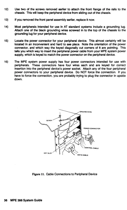
panel assembly earlier, replace It now.14) Most peripherals Intended for use In AT standard systems Include a grounding lug. Attach
one
of the black grounding wires screwed In to the top of the chassis to the grounding lug for your peripheral device.15) Locate the power connector for your peripheral device. This almost certainly will be located In an Inconvenient and
hard
tosee
place. Note the orientation of the power connector, and which way the keyed diagonally cut corners of It are pointing. This tells you which way to insert the peripheral power cable from your MPE system power supply, which is keyed to match the power connectoron
the peripheral device. [image:44.612.82.514.63.775.2]16) The MPE system power supply has four power connectors Intended for use with peripherals. These connectors have four wires each and are keyed for correct insertion into the peripheral device's power socket. Attach any of the four peripheral power connectors to your peripheral device. Do NOT force the connection. If you have to force the connection, you are probably trying to plug the connector in upside down.
Figure 11. Cable Connections to Peripheral Device
17) Attach any cables running from the peripheral device to the card which controls It. 18) Double check all cable connections. Make sure any keyed cables are correctly
Inserted.
5. External Options Installation
This section describes how to install your system together with external components like monitors and keyboards.
5.1 Site Selection and Preparation
The following parameters are Important when choosing a site for your MPE system. These factors are Important both to your safety as well as to the safety of your system:
• Locate your MPE system In a clean, dry area that enjoys well regulated temperatures. Avoid placing the system too close to heaters, radiators, or other sources of heat. Do not locate the system where direct sunlight may cause it to heat up above ambient temperatures.
• Select a well-constructed work table or support surface for your MPE system. Do not place the MPE on an unstable cart, stand or table. If the system falls from an inadequate table serious damage could result.
• Slots and openings in the chassis and cover are provided for ventilation; to ensure reliable operation of the MPE system and to protect it from overheating these openings must not be blocked or covered. The openings should never be blocked by placing the product on a soft surface like a rug, sofa, or similar surface. Do not install the MPE system in a built-in cabinet or rack unless proper ventilation is provided.
• The MPE system must be operated from the type of AC power source indicated on the rear panel markings. If you are not sure of the type of power available, contact your system vendor or local power company.
• This product is equipped with a 3-wire grounding. type plug, a plug having a third (grounding) pin. This plug will only fit into a grounding-type power outlet. This is an important safety feature. If you are unable to insert the plug into the outlet, contact your electrician to provide a grounding-type outlet. Do not defeat the purpose of the grounding-type plug.
• Do not allow anything to rest on the power cord. Do not locate the MPE system where persons will walk on the power cord.
• If an extension cord is used with the MPE system, make sure that the total of the ampere ratings on the products plugged Into the extension cord does not exceed the extension cord ampere rating. In addition, make sure that the total of all products plugged into the wall outlet does not exceed 15 amperes or the maximum amperes supported by your wall outlet, whichever is less.
• Never push objects of any kind Into the MPE 386 through the chassis or cover slots. They may touch dangerous voltage points or short out parts that could result in a risk of fire or electric shock. Do not locate the MPE system where liquids of any kind may be spilled on it.
5.2 Getting Ready For Operation
Set the MPE system In Its operating location. Ready it for operation with the following steps:
1) Remove the shipping Inserts from the floppy disk drive and tape mechanism. if Installed.
2) Make sure the 115V - 230V voltage selector switch is set to the right voltage. In the United States,
set
the switch to 115V.[]]I
ScrewdriverSelector Switch