© 2019, IRJET | Impact Factor value: 7.211 | ISO 9001:2008 Certified Journal | Page 7378
Design and Performance Curve Generation by CFD Analysis of
Centrifugal Pump
Supriya Jadhav
1, Vaibhav Ghodake
2, Pavan Chipade
3, Shubham Gaikwad
4,
Vikram Ghule
5,
Nilesh Gaidhani
61
Supriya Jadhav, UG student, Dr. D Y Patil School of Engineering, Pune
2
Vaibhav Ghodake, UG student, Dr. D Y Patil School of Engineering, Pune
3
Pavan Chipade, UG student, Dr. D Y Patil School of Engineering, Pune
4
Shubham Gaikwad, UG student, Dr. D Y Patil School of Engineering, Pune
5
vikram Ghule, Professor, Dept. of mechanical Engineering, Dr. D Y Patil School of Engineering, Pune
6
Nilesh Gaidhani, Design Executive Indo Pump, Pune.
---***---Abstract
- This work investigates a systematic numericalapproach that employs Computational Fluid Dynamics (CFD) to obtain performance curves of a backward-curved centrifugal pump. Capacity curve obtained from the CFDS analysis of centrifugal pump gives wide approach to parameters such as cavitation and reverse flow. Semi open impeller with single volute casing defines the path of flow. This study is focused on effect varying discharge on its performance parameters such as head, required power and efficiency. Head discharge relation will give ease of pump selection. Mesh generation technique had discussed in the project work for better CFD results.
Key Words: pump design, construction of blade, CFD analysis, cavitation, performance curve.
1.INTRODUCTION
A pump is a mechanical device for moving a fluid from a lower to a higher location or from lower to higher pressure area. Performance of the ump may be affected due to some geometrical and input parameters such as blade angle, impeller size, discharge and head required. To overcome the problem, designers often change the geometry of the pump selection parameters. Specific speed determines the geometry of the impeller and forces in pump due to fluid flow whole design may be depend on the performance curve generation which helps the overcome the selection problem s and the required BEP. While overcoming the losses the designed modification can be done.
1.1 OBJECTIVES
1. Familiar approach to improve the design of centrifugal pump and optimize its operational parameters.
2. To study the centrifugal pump approaching towards the radial flow pumps.
3. To evaluate pressure distribution at blade and shroud region of the centrifugal pump.
4. To obtain the optimum pump impeller design for effective suction of pump.
5. Plot performance curve of pump (H&Q curve, Efficiency vs. discharge vs. head curve).
6. To investigate the effective of impeller geometry on pump performance.
7. To analyze the effect of variable discharge on cavitation pressure counters at impeller blade. 8. To check the performance of pump such as efficiency, hydraulic power output wrt varying discharge.
1.2 METHODOLOGY
© 2019, IRJET | Impact Factor value: 7.211 | ISO 9001:2008 Certified Journal | Page 7379
2. DESIGN AND DEVELOPMENT
2.1 Impeller
Pump have to carry 1000m3/hr with abrasive material
[image:2.595.317.568.73.301.2]for the total head of 75 m from the storage tank at atmospheric pressure. Specific gravity of fluid flowing through the pump is 1.0. Pump having the speed for impeller is 1450 rpm. The overall efficiency is assumed to be 80% for the pump. While designing the pump, design will tends towards the missed flow region. While designing the pump modification in the design may vary with respect to results.
Table -1 Dimensions of Impeller
Parameters Dimensions
Outside diameter ( 530 mm
Eye diameter ( 288 mm- 290
Vane inlet edge diameter ( 289mm
Outlet width 44 mm
Inlet width ( ) 81 mm
Diameter of shaft ( 59 mm
Vane inlet angle
Vane outlet angle (
Vane thickness ( t) 8 mm
[image:2.595.32.281.289.565.2]
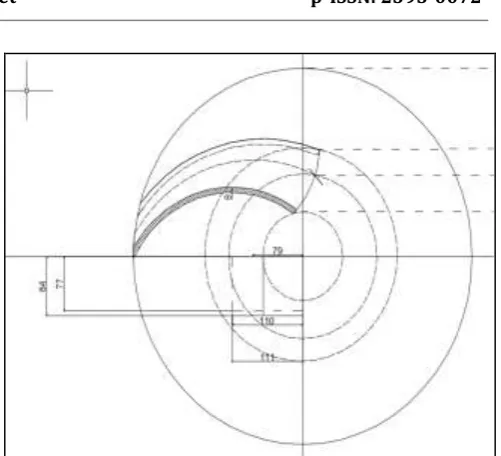
Genration of impeller blade is mainly focused on the blade curveture. Bl;ade curveture the pump performance as it seprstes pressure regions. Blade curve is genrated by multiple arc method.in multiple arc method, impeller is divided into 6-8 curves. Final blade curve genrated is replica of the curves in each section. Also impeller shroud is designed with inlet and outlet width dimensions for smooth flow of fluid.
Fig.2 Blade curve by multiple arc method
Fig.3 Developement of shroud
[image:2.595.319.570.342.541.2]© 2019, IRJET | Impact Factor value: 7.211 | ISO 9001:2008 Certified Journal | Page 7380
Volute of centrifugal pump is generated in software CF
Turbo. CF turbo is popular tool for impeller and volute generation due to Rapid design of hydraulic high-quality pumps. Integration of established pump design theory. Comfortable, reliable and user friendly Direct interfaces for many CAE-software packages .Comprehensive and detailed documentation manual.
Table-2 Input parameters for volute in CF Turbo
Required discharge 1000
Head required 75 m
Inner diameter 557 mm
Inner width of volute 90 mm
Outlet nozzle diameter 250nmm
Neck of volute
Fig.4 Generation Single volute in CF turbo
3. MODIFICATIONS OF STATOR COMPONENT:-
3.1 In-pipe And Elbow:
In pipe is used to guide the inlet water to the elbow. Elbow is intermediate part between the Inpipe and impeller shroud. Fig (2). Interference is created between the Inpipe elbow and impeller in CFX pre.
3.2 Out-pipe
Function is to guide the flow of water coming out from the volute casting. This is required to minimize the whirl component and to achieve better results.
Table-3 dimensions of auxiliary components
Element Diameter length
In Pipe 250 1000
Elbow 250-290 175
Out pipe 250 500
Interference is creates between the Inpipe and Elbow is needed during CFD simulations, so the dimensions must match with other component. Outpipe coming out from the casing outlet is increasing in cross-sectional area to create more head at outlet by converting the kinetic energy into pressure.
Fig.5 auxiliary component Inlet pipe, Elbow, Outlet pipe
4. CFD ANALYSIS
As the impeller moves through the fluid, low-pressure areas are formed because the fluid accelerates around the blades. The higher the fluid velocity, the lower becomes the local pressure. If it falls below vapor pressure, the fluid vaporizes and forms small bubbles of gas. These are dragged to areas of higher pressure, where they collapse and can cause very strong local shockwaves in the fluid, which may even damage the blades. CFD helps to design pumps with favorable cavitation behavior over a wide operating range
.
i) Preparation of surface model of the impeller and Casing using software like PRO-E, CATIA, Uni-Graphics.
© 2019, IRJET | Impact Factor value: 7.211 | ISO 9001:2008 Certified Journal | Page 7381
iii) Application of boundary conditions using software likeCFX PRE.
iv) Solution and analysis of results using software like ANSYS-CFX POST, Fluent.
v) Analysis of flow through hydraulic passages and prediction of pump performance
characteristics by application of computational fluid dynamic (CFD) techniques.
4.1. MESHING
The subdivision of the domain into no of smaller, non-overlapping sub-domains: a grid (or mesh) of cells (or control volumes or elements).For the meshing of impeller we used hexahedral mesh and for the volute we used tetrahedral mesh.
Meshing plays main role in the outcome of the cfd results. fine mesh is required near the region where more chances of turbulence, cavitations such as impeller blade wall, volute tongue and low pressure regions. Different meshing techniques can be used to generate the mesh to different parts of pump. Also the condition of surfaces and quantity play main role in mesh quality. For the same degree of polynomial the finite element space generated by hexahedral elements is richer than the space generated by tetrahedral elements. However the tetrahedral elements are best to model complex geometry domain with little distortion of mesh. Moreover, the computational cost for assembling the global stiffness matrix for tetrahedral elements is lower because there is not necessary numerical integration.
Table-3 The mesh statistics is given bellow for each component:-
Sr.
no Component Mesh type Node point Element No.
1 Impeller(Rot ating Domain)
Hexahedral 2308800 2438112
2 volute Tetrahedral 564769 1920449
3 In pipe Hexahedral 237600 244900
4 Out pipe Tetrahedral 34435 93026
5 Elbow Hexahedral 408988 398634
Fig.5 Blocking of impeller
Fig.6 Hexahedral mesh for single fluid passage
© 2019, IRJET | Impact Factor value: 7.211 | ISO 9001:2008 Certified Journal | Page 7382
Fig.7 Tetrahedral Meshing of voluteFig. 8 Meshing of In pipe, Out pipe and Elbow pipe
4.2 Boundary Conditions
Pre-processing consist of the input flow problem to cfd program by means of operator friendly interface and subsequent transformation of this input into a form suitable for use by the solver. The user activities at the preprocessing stage involve:
1. Selection of physical and chemical phenomenon that need to be modelled.
2. Definition of fluid properties, fluid is water hence select the water as fluid.
3. Specification of appropriate boundary condition at cells which coincide with or touch the domain boundary. We give boundary condition as the flow rate of 1000 m3 /hr, and speed of 1450 rpm
as per our problem statement. Inlet discharge conditions vary in 250, 500, 750, 1000,1250, 1500,1750 m3/hr.
4. Boundary conditions given to the pump are depends upon the type input data and desired results.
5. Input to impeller is given in mass flow rate condition in kg / sec.
6. For rotating domain in pump, wall are consider as the no slip wall and coordinate frame as the rotating.
[image:5.595.322.554.269.530.2]7. For stator domain, wall is considered as No slip wall and wall roughness consider as smooth wall.
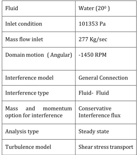
Table-4 Boundary condition given to CFX Pre
Fluid Water (200 )
Inlet condition 101353 Pa
Mass flow inlet 277 Kg/sec
Domain motion ( Angular) -1450 RPM
Interference model General Connection
Interference type Fluid- Fluid
Mass and momentum
option for interference Conservative Interference flux
Analysis type Steady state
Turbulence model Shear stress transport
5. RESULTS
Visualization of the counters of pressure and velocity variation are presented bellow. This contours give the better understanding of low and high pressure areas which are useful in modification in geometrical parameters. [image:5.595.38.274.337.499.2]
© 2019, IRJET | Impact Factor value: 7.211 | ISO 9001:2008 Certified Journal | Page 7383
Table-5 Result table at 1000 m3/hrMass flow rate
277 kg/sec
Total pressure inlet
-799659 [Pa]
Total pressure outlet
17193.4 [Pa]
Volumetric efficiency
96.4123 %
Impeller efficiency
80.57 %
RPM
1450
Overall efficiency
75.37%
Total head output
83.51 m
Hydraulic power
237751 [W]
Total torque
1982.92 J
5.1 Pressure and velocity distribution for
different discharge
Fig.9 Pressure distribution in the pump volume at 1000 m3/hr
Fig.9
Pressure distribution over the blades at 1000 m3/hr© 2019, IRJET | Impact Factor value: 7.211 | ISO 9001:2008 Certified Journal | Page 7384
Fig.11 Velocity distribution at 250 m3 /hrFig.12 Pressure distribution at 250 m3 /hr
Fig.13 Velocity distribution at 500 m3 /hr
Fig.14 Pressure distribution at 500 m3
/hr
Fig.15 Pressure distribution at 750 m3
/hr
© 2019, IRJET | Impact Factor value: 7.211 | ISO 9001:2008 Certified Journal | Page 7385
Fig.17 Pressure distribution at 1250 m3/hr
Fig.18 Velocity distribution at 1250 m3 /hr
Fig.19 Pressure distribution at 1500 m3
/hr
Fig.20 Velocity distribution at 1500 m3 /hr
Fig.21 Pressure distribution at 1500 m3
/hr
© 2019, IRJET | Impact Factor value: 7.211 | ISO 9001:2008 Certified Journal | Page 7386
Graph-1 Performance curve3. CONCLUSIONS
The pump performance calculated by the cfd simulations is well suitable for the given pump requirement. The required head is 77m and designed head of impeller id between 89 m. After simulation of pump, results satisfactory with total head of 83 m , which Is above the required head.
Observations obtained are bellow:-
1. As discharge increases, the power is increases in constant proportion.
2. At low discharge condition( 250, 500 m3/hr),
pressure distribution at volute is dense and increase rapidly. Cavitation is seems to be more near blade inward curve side.
3. Pump efficiency is higher at 1000- 1200 m3/ hr
range. Pump performance is satisfactory at our designed condition (1000 m3/ hr).
4. Whirl component is more at volute neck, means back flow is observed at neck and impeller- volute interface.
5. Efficiency of the pump likely to be reduced after 1500 m3/hr. Head also reduced sharply.
6. At lower discharge condition, pump is showing vibration, uneven pressure and velocity distribution.
REFERENCES
[1] Mohamad hazeri Ismail. Design and development of centrifugal pump impeller for performance enhancement. https://www.researchgate.net/publication/285055176
[2] Farah Elida Selamat. Design and Analysis of Centrifugal Pump Impeller for Performance Enhancement.Journal of Mechanical Engineering Vol SI 5(2), 36-53, 2018
[3] David Cowan, Thomas Liebner, Simon Bradshaw. . Influence of impeller suction specific speed on vibration performance. Proceedings of the Twenty-Ninth International Pump Users Symposium October 1-3, 2013, Houston, Texas
[4] Jianhua Liu, Xiangyang Zhao and Miaoxin Xiao. Study on the Design Method of Impeller on Low Specific Speed Centrifugal Pump. The Open Mechanical Engineering Journal, 2015, 9, 594-600
[5] Mukesh Sahdev. Basics Concepts of operation, Maintenance, and Troubleshooting. The Chemical Engineers’ Resource Page, www.cheresources.com
[6] Marcus Beck, Paul Uwe Thamsen. How to design a centrifugal pump with constant power consumption for all flow rates Distributed under a Creative Commons Attribution| 4.0 International License https://hal.archives-ouvertes.fr/hal-01549128
[7] R. M. Pande, S. U. Kandharkar, R. B. Patthe, V.M.Nandedkar, V.B. Tungikar. Computational Fluid Dynamics (CFD) of Centrifugal Pump to Study the Cavitation Effect. International Journal on Theoretical and Applied Research in Mechanical Engineering (IJTARME)
[8] Tilahun Nigussie, Edessa Dribssa Design and CFD Analysis of Centrifugal Pump International Journal of Engineering Research and General Science Volume 3, Issue 3, May-June, 2015
[9] Raghavendra S Muttalli , Shweta Agrawal , Harshla Warudkar , CFD Simulation of Centrifugal Pump Impeller Using ANSYS-CFX International Journal of Innovative Research in Science, Engineering and Technology
[10] Mr. Nilesh Patil , Prof.G.S.Joshi , Prof.Dr.V.R.Naik Validation in the improved performance of Centrifugal pump using CFD International Research Journal of Engineering and Technology (IRJET)
© 2019, IRJET | Impact Factor value: 7.211 | ISO 9001:2008 Certified Journal | Page 7387
[12] Mehta Mehul Pravinchandra Improving The HeadAnd Efficiency of A Pump 2016 IJEDR | Volume 4, Issue 2