© 2019, IRJET | Impact Factor value: 7.211 | ISO 9001:2008 Certified Journal | Page 6367
Comparative Study of Multi-Storey Multi-Span G+4 Building by PEB and
CSB Concept
Md ShahidWasim Chaudhary
1, Vishwajeet Kadlag
2, Dr. Nagesh Shelke
31
M.E.(Structures) Student, Department of Civil Engineering Dr. D Y Patil School of Engineering and Technology,
Charholi (BK), Pune-412 105, Maharashtra, India
2,3
Professor, Dept. of Civil Engineering, Dr. D Y Patil School of Engineering and Technology, Charholi (BK),
Pune-412 105 Pune, Maharashtra, India
---***---Abstract
:
Time being the most important aspect, steel structures (Pre fabricated) is built in very short period and one such example is Pre Engineered Buildings (PEB)..Though it is known to have its origin in 1960’s it has been in practice widely only during the recent years. Steel industry is growing rapidly in almost all the parts of the world. Conventional steel buildings and Pre Engineered Buildings can be used extensively for the construction of Industrial , Commercial and Residential Buildings .These buildings can be multistoried (4-6 floors).The adoptability of PEB in the place of Conventional Steel Building (CSB) design concept resulted in many advantages, including economy and easier fabrication. Construction of conventional steel buildings (CSB) incorporates the use of hot rolled sections, which have uniform cross-section throughout the length. However, pre-engineered steel buildings (PEB) utilize steel sections, which are tailored and profiled based on the required loading effects. The concept includes the technique of providing the best possible section according to the optimum requirement. Due to lack of awareness and confidence in design and execution of PEB buildings, still it is not the first choice of owner and designer in India. This paper gives a comparative study of PEB and CSB Concept for multi-storey building .This is achieved by analyzing and designing G+4 commercial building with length 140m ,width 40m,eave height 18m, R slope 1/10 using STADD PRO and IS 800-2007 Design code ,by both concepts.
Key Words
:
Pre-Engineered Building, Conventional Steel Building, Staad Pro , IS 800-20071. INTRODUCTION
Steel industry is growing rapidly in almost all the parts of the world. The use of steel structures is not only economical but also Eco-friendly at the time when there is a threat of global warming. Here, “economical” word is stated considering time and cost. Time being the most important aspect, steel structures (Pre-fabricated) is built in very short period and one such example is Pre Engineered Buildings (PEB). Pre-engineered buildings are nothing but steel buildings in which excess steel is avoided by tapering the sections as per the bending moment’s requirement. One may think about its possibility, but it’s a fact many people are not aware about Pre Engineered Buildings. If we go for regular steel structures, time frame will be more, and also cost will be more, and both together i.e. time and cost, makes it uneconomical. Thus in pre-engineered buildings, the total design is done in the factory, and as per the design, members are pre-fabricated and then transported to the site where they are erected in a time less than 6 to 8 weeks. The structural performance of these buildings is well understood and, for the most part, adequate code provisions are currently in place to ensure satisfactory behavior in high winds. Steel structures also have much better strength-to-weight ratios than RCC and they also can be easily dismantled. Pre Engineered Buildings have bolted connections and hence can also be reused after dismantling. Thus, pre-engineered buildings can be shifted and/or expanded as per the requirements in future. Presently, large column free area is the utmost requirement for any type of industry and with the advent of computer software’s it is now easily possible. With the improvement in technology, computer software’s have contributed immensely to the enhancement of quality of life through new researches. Pre-engineered building (PEB) is one of such revolution. "Pre-engineered buildings" are fully fabricated in the factory after designing, then transported to the site in completely knocked down (CKD) condition and all components are assembled and erected with nut-bolts, thereby reducing the time of completion.
2.
METHODOLOGY
© 2019, IRJET | Impact Factor value: 7.211 | ISO 9001:2008 Certified Journal | Page 6368
the designs are then compared to find out the economic output and steel consumption. The designs are carried out in accordance with the Indian Standards and by the help of the structural analysis and design software Staad.pro.
2.1 Concept Of
Pre Engineered Buildings
These are produced in the plant itself. Here, according to the requirements of the customer the manufacturing of the members is done. The components are made in completely ready condition for transportation. These are then sent to the site and then the erection process starts. The manufacturing process doesn’t takes place at the site. The PEBs are normally constructed for office, shop fronts, ware houses, etc. Here, the extra amount of steel is avoided because the sections are tapered according to the bending moment diagram. Pre-Engineered Building concept involves the steel building structural systems which are predesigned and prefabricated .
In today’s 21st century, it is very important to find an alternate resource for civil construction technology, seeing through the depleting natural resources. In India, the concept of PEB construction started in 1999-2000. The growth rate of PEB construction is 20 percent annually. PEB concept has been very successful and well established in North America, Australia and is presently expanding in U.K and European countries.
Fig-1: G+4 PEB Frame
2.2 Concept Of
Conventional Steel Buildings
Today’s world, steel is bringing elegance, artistry and is functioning in endless ways contributing to new solutions for the construction of formidable structures, which were once unthinkable. Steel offers speedy construction right from the start . Due to its important characteristics like ductility, flexibility etc. steel is been widely used in the construction industry. It bends under the application of heavy loads rather than undergoing crushing and crumbling .
Due to its strength, less rate, stability, flexibility and recyclability, it makes a great choice to use steel in construction. It is also seen that steel has some reserve strength in them. The CSBs are stable . Usually hot rolled structural members are used in these buildings. Here the members are fabricated in factories and then transported to the site. The changes can be made during the erection by welding and cutting process. Normally trusses are used in this system.
© 2019, IRJET | Impact Factor value: 7.211 | ISO 9001:2008 Certified Journal | Page 6369
3.
Structure Configuration
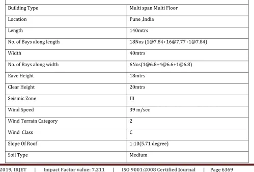
[image:3.595.48.548.455.793.2]The structure which I considered now is a G+4 Commercial Building located in Pune having its dimensions as 140m length and 40m width having a eave height of 18m with 5 no. of internal column which is at a distance of 1 @ 6.8m C/C + 1 @ 6.6m C/C + 1 @ 6.6m C/C+6.8m C/C + 1 @ 6.6m C/C + 1 @ 6.6m C/C. As the building in Pune is falls under seismic zone-III with a wind speed of 39m/s i.e. 140Kmph. As the structure is having regular intermediate column spacing the structure be symmetric to its ridge. The details of parameters are provided in table 1
Fig-3: 3D Frame Staad Model
Table -I:
STRUCTURE CONFIGURATION DETAILS
Building Type Multi span Multi Floor
Location Pune ,India
Length 140mtrs
No. of Bays along length 18Nos ([email protected][email protected][email protected])
Width 40mtrs
No. of Bays along width 6Nos([email protected][email protected][email protected])
Eave Height 18mtrs
Clear Height 20mtrs
Seismic Zone III
Wind Speed 39 m/sec
Wind Terrain Category 2
Wind Class C
Slope Of Roof 1:10(5.71 degree)
© 2019, IRJET | Impact Factor value: 7.211 | ISO 9001:2008 Certified Journal | Page 6370
Importance Factor 1
Roof Purlins Span 7.77m continuous spaced @1.5m c/c.
Wall Girts Span 7.77m continuous spaced @1.5m c/c.
4. Load Data
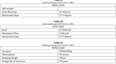
[image:4.595.53.551.47.170.2]IS 800:2007-Clause 3.2 states that the various forces and loads must be considered while performing the design of steel structures . Loading details are given in below Tables II, III & IV.
Table II
Dead load (As per IS 875-Part 1, 1987) DEAD LOAD
Self-weight
Deck Sheeting 0.1 kN/m2
Horizontal slope 5.71 degree
Table III
Dead load (As per IS 875-Part 2, 1987) LIVE LOAD
Roof 0.75kN/m2
Mezzanine Floor 5 kN/m2
Horizontal slope 5.71 degree
Table IV
Wind load (As per IS 875-Part 3, 1987) WIND LOAD
Location PUNE,INDIA
Wind Speed 39 m/sec
Building Height 20mtr
Design life of structure 50 years
Wind load is calculated as per IS:875 (Part 3)-1987. The wind load over the roof can be provided as uniformly distributed load acting outward over the rafter. For side walls, the wind load is applied as uniformly distributed loads acting inward or outward to the walls according to the wind case.
Design wind speed as per Clause 5.3, IS:875 (Part 3) – 1987 is given by,
Vz = Vb * k1 * k2 * k3 For Pune, Vb = 39 m/s, from appendix A as per IS: 875 (Part 3) – 1987 k1 = 1.00, from table 1 as per IS: 875 (Part 3) – 1987
k2 = 0.99, from table 2 for terrain category 2- Class C buildings k3 = 1,
Therefore Design wind speed (Vz) = Vb * k1 * k2 * k3 = 39 * 1.0 * 0.99* 1.0
= 38.61 m/s
5. Design wind loads:
[image:4.595.55.539.245.513.2]© 2019, IRJET | Impact Factor value: 7.211 | ISO 9001:2008 Certified Journal | Page 6371 SIGN CONVENTIONS
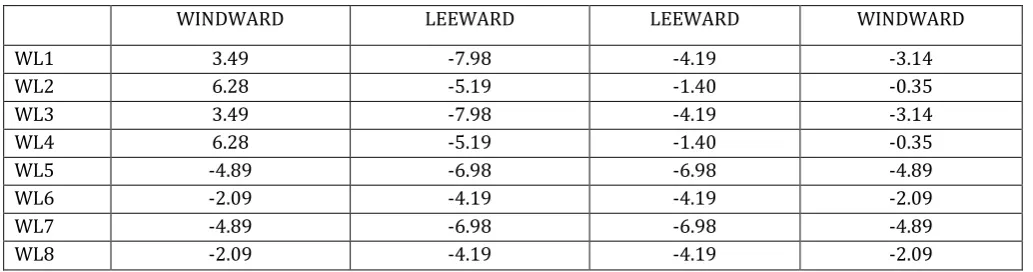
[image:5.595.41.558.167.303.2]+ve sign indicates wind flows towards frame -ve sign indicates wind flows away from frame.
Table V:Final wind loads (kN/m)
WINDWARD LEEWARD LEEWARD WINDWARD
WL1 3.49 -7.98 -4.19 -3.14
WL2 6.28 -5.19 -1.40 -0.35
WL3 3.49 -7.98 -4.19 -3.14
WL4 6.28 -5.19 -1.40 -0.35
WL5 -4.89 -6.98 -6.98 -4.89
WL6 -2.09 -4.19 -4.19 -2.09
WL7 -4.89 -6.98 -6.98 -4.89
WL8 -2.09 -4.19 -4.19 -2.09
6. Load combinations:
For the present study, various primary loads are considered as given below.
1.EQX +VE
2.EQX –VE
3.EQZ+VE
4.EQZ-VE
5.DL
6.LL
7.WL1
8.WL2
9.WL3
10.WL4
11.WL5
12.WL6
13.WL7
14.WL8
For these primary loads, following are the combinations adopted for the analysis in both the concepts according to IS 800: 2007
© 2019, IRJET | Impact Factor value: 7.211 | ISO 9001:2008 Certified Journal | Page 6372 (DL+WL/EL)
(DL+LL+CL)
(DL+0.8*LL+0.8*WL/EL+0.8*CL) Design combinations:
1.5*(DL+LL) 1.5*(DL+WL/EL) (0.9*DL+1.5 WL/EL) (1.5*DL+1.5*LL+1.05*CL) (1.5*DL+1.05*LL+1.5*CL)
[image:6.595.130.467.308.562.2](1.2*DL+1.2*LL+0.6*WL/EL+1.05*CL) (1.2*DL+1.05*LL+0.6*WL/EL+1.2*CL) (1.2*DL+1.2*LL+1.2 *WL/EL+0.53*CL) (1.2*DL+1.2*LL+1.2*WL/EL+0.53*CL)
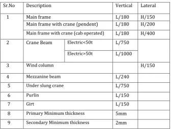
Table VI: Deflection Limits According to IS 800-2007
Sr.No Description Vertical Lateral
1 Main frame L/180 H/150
Main frame with crane (pendent) L/180 H/200
Main frame with crane (cab operated) L/180 H/400
2 Crane Beam Electric<50t L/750
Electric>50t L/1000
3 Wind column H/150
4 Mezzanine beam L/240
5 Under slung crane L/750
6 Purlin L/150
7 Girt L/150
8 Primary Minimum thickness 5mm
© 2019, IRJET | Impact Factor value: 7.211 | ISO 9001:2008 Certified Journal | Page 6373 Table VII :Limiting Width to Thickness Ratio According to IS 800 -2007-Table-2
Compression Ratio Class of section
Class 1 Class 2 Class 3(Semi- (Plastic) (Compact) Compact) Outstanding element of Rolled section b/tf 9.4 10.5 15.7
compression flange Welded section b/tf 8.4 9.4 13.6
Internal element of Compression due to bending b/tf 29.3 33.5 42
compression flange Axial compression b/tf Not applicable
Web of an I,H or box
section Neutral axis at mid-depth d/tw 84 105 126
d/tw (84 )/(1+r1) (105 )/(1+r1) (126 )/(1+2r2)
Generally If r1 is negative but 42 but 42 If r1 is
positive d/tw (105 )/(1+1.5r1)
Axial compression but 42
d/tw Not applicable 42
Web of a channel d/tw 42 42 42
Angle, compression due to bending (Both criteria should be b/t 9.4 10.5 15.7
satisfied) d/t 9.4 10.5 15.7
Single angle, or double angles with the components separated, b/t 15.7 axial compression (All three criteria should be satisfied) d/t Not applicable 15.7
(b+d)/t 25
Outstanding leg of an angle in contact back-to-back in a double d/t 9.4 10.5 15.7 angle member
outstanding leg of an angle with its back in continuous contact d/t 9.4 10.5 15.7 with another component
Stem of a T-section, rolled or cut from a rolled I-or H- section D/tf 8.4 9.4 18.9 Circular hollow tube, including welded tube subjected to:
a) Moment D/t 42 2 52 2 146 2
b) Axial compression D/t Not applicable 88 2
1. Elements which exceed semi-compact limits are to be taken as of slender cross-section. 2. = (250 /fy) 1/2.
3. The stress ratio r1 and r2are defined as:
r1 = (Actual average axial stress(negative if tensile)/(Design compressive stress of web alone)
r2 = (Actual average axial stress(negative if tensile)/(Design compressive stress of overall section)
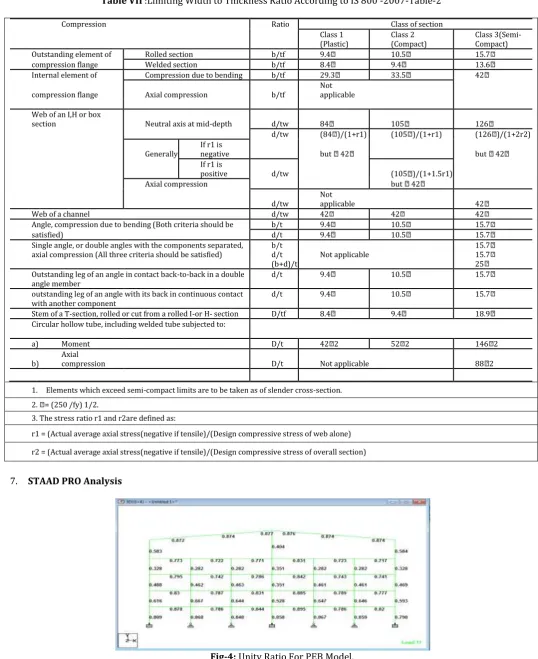
7. STAAD PRO Analysis
© 2019, IRJET | Impact Factor value: 7.211 | ISO 9001:2008 Certified Journal | Page 6374 Fig-5: Max Bending Moment For CSB Frame.
Fig-6: Max Bending Moment For PEB Frame.
8. Results And Discussion
Using the software Staad pro, the structure considered was analyzed and designed using both the PEB and CSB concept and obtained results are summarized as below in table VIII with reference to figure 5 and 6.
Table VIII: Outcomes Of Study
SR.NO PARAMETER PEB CSB
1 STEEL TAKE OFF (kN) 6088.82 10084.4
2 MAXIMUM MOMENT (kNm) 745.026 795.335
3 MAXIMUM SHEAR FORCE (kN) 2683 2852.931
[image:8.595.54.541.310.532.2]© 2019, IRJET | Impact Factor value: 7.211 | ISO 9001:2008 Certified Journal | Page 6375 9. CONCLUSIONS
The paper contain the study for analysis and design of G+4 multistoried multi-span building as per PEB and CSB Concept. The results obtained from study shows that multistoried building of PEB are also advantageous over CSB and should be adoptable by the designers and owners in India.
The various outcomes from the study are as belows
1. As per study it has been observed that the weight of PEB model is lesser than that of the CSB model of same length width and height. Reduction in weight directly deals with the quantity of steel required, here in these study of G+4 commercial PEB structure reduces the quantity of steel by about 39% than that required by the G+4 commercial CSB structure.
2. As of the quantity of steel , also Moment, Shear Forces and Support Reactions are lesser than the CSB which in turn reduces the heavy work, cost saving and also material saving in the structure.
3. PEB structures are lighter than CSB structures , hence provide good resistance to Seismic forces .
4. Delivery and Erection time for PEB is also less as compared to CSB , as they are manufactured in factories and just erected using nut and bolts on site, these makes the work faster and easier.
5. The construction of PEB structure is lighter , faster, cost and material saver than CSB , and has a very wide scope in India but they are still not preferred .
6. PEB technology can be adopted for the bigger sized buildings more effectively than the smaller sized buildings . 10. REFERENCES
1. IS: 800 - 2007 :- General Construction In Steel- Code of Practice.
2. IS: 875 (Part 1) – 1987: Code of Practice for Design Loads (Other Than Earthquake) forBuildings and Structures- Dead Loads.
3. IS: 875 (Part 2) - 1987: Code of Practice for Design Loads (Other Than Earthquake) for Buildings And Structures- Live Loads.
4. IS: 875 (Part 3) - 1987: Code of Practice for Design Loads (Other Than Earthquake) for Buildings and Structures- Wind Loads.
5. Dr. N. Subramanian, “Design of Steel Structures”
6. Kavya.Rao.M.N1, K.N.Vishwanath2, Design Optimisation of an Industrial Structure from Steel Frame to Pre-Engineered Building. International Journal of Research in Advent Technology, Vol.2, No.9, September 2014 E-ISSN: 2321-9637 7. C. M. Meera (June 2013). Pre engineered building design of an industrial warehouse. International journal of
engineering sciences & emerging technologies. Volume 5 Issue 2 , pp:75-82
8. Aijaz Ahmad Zende, Prof. A. V. Kulkarni, Aslam Hutagi (Feb 2013) . Comparative Study of Analysis and Design of Pre-Engineered- Buildings and Conventional Frames. IOSR Journal of Mechanical and Civil Engineering, Volume 5, Issue . 9. Syed Firoz1, Sarath Chandra Kumar B1,Design concept of pre engineered building. International journal of engineering
research & applications, volume 2 , issue 2 , pp:267-272
10. G. Sai Kiran , A. Kailasa Rao, R . Pradeep Kumar (Aug 2014) . Comparison of Design Procedures for Pre Engineering Buildings (PEB): A Case Study. International Journal of Civil, Architectural, Structural & Contruction Engineering, Volume 8, No. 4
11. Karnav Sukhadia*1, Vijay R. Panchal2, Vikram M. Patel3, Ravikumar Ganti4, Comparative Study of PEB Industrial Building with CSB Industrial Building, 2nd International Conference on Current Research Trends in Engineering and Technology, 2018 IJSRSET,Volume 4,Issue 5.