© 2019, IRJET | Impact Factor value: 7.211 | ISO 9001:2008 Certified Journal | Page 4853
COMPARATIVE STUDY OF DIFFERENT POSITION OF SHEAR WALL
USING SOFTWARE
Mukund kapadia
1, Ankit mistry
2, Bhargav gohil
3, Ashwin sutaria
4, Bhavin godhani
5,
Guide Prof. Kevan DC
1,2,3,4,5
Student, Department of civil Engineering, MSCET, Surat, Gujarat, India
6Professor, Dept. of Civil Engineering, MSCET, Surat, Gujarat, India
---***---Abstract –
A India is earthquake prone country. Hence, thestructures response is considering under wind and seismic load effect are very important. The effect seismic force and wind force is very important for design the height of buildings. Therefore, it is necessity to consider effects of lateral loads produce due to earthquakes and wind. The structural is a residential multi storey building. The typical structure design is assembly between the footing, columns, beams and slabs. The present project consists the analysis of a multi-storey residential building of G+13 have 4 flat sat each storey. The different structural loadings are calculating, obtained as per Indian standard to applied and the design for beams and columns. The structure model without RCC shear wall and same model with RCC shear wall and the effect due to change in position of RCC shear wall is consider, analysis and comparative study has been carried out. Software STAAD PRO V8I is used for the analysis. The result such as for different load are studied. Comparison done for models carrying RCC shear walls at different position to choose best design for wind load, earthquake load, live load, and dead load to reduce the damage and increase performance.
Key Words: STAAD PRO V8I, Shear wall, RCC, Axial force, Bending
1. INTRODUCTION
The shear wall is structural vertical member that is able to withstand against combination of axial force, shear and moment load produce through applied lateral and gravity load from other member in structure. RCC shear walls are most commonly provide in high-rise multi-story buildings to achieve better reduction in bending moment and shear failure. Shear wall is like vertical rigid diaphragm plate that capable to transfer horizontal load. This wall generally starts at foundation level and are continuous through the building height. Shear wall has adequate strength and stiffness to control lateral displacements. The shear wall is composition of large and wide RCC columns. Thickness can be as low as 150 mm, or as high as 400 mm in high rise buildings. Shear wall may become imperative from the point of view of economy and control of lateral deflection. In RC multi-storey building well shape and plan position of the shear wall consider in the behavior of the structure. The best position for the shear walls is in the center of each half of the
building. Center of mass and building stiffness is considering for a Structure.
2. METHODOLOGY
For Modeling and analysis of structure the” STAAD PRO V8I” has been used. It is based on finite element method. The planning is done using AUTOCAD. The space frame G+13 model is prepared. Column base are assigned as fixed support. Column and beam are assigned and shear wall assigned as plate element.
Building having a RCC shear wall throughout the height of building. Details of multistory frame building are: G+13 storey, Floor to floor height: 3 m Seismic zone: Zone IV(Surat), Soil type: soft soil. Shear wall: 230 mm thick and RCC slab: 150 mm thick and load cases used for analysis.
For RCC design Concrete grade: M30 and All steel grades: Fe415.
3. LOAD CASES
Dead load = Self-weight of structural elements
Live load (IS875:1987)
1. rooms and kitchen = 2kn/m2
2. corridors, passages, staircases, fire escapes, store rooms and balconies for residential = 3kn/m2
Wind load (IS875:1987)
1. Building Height: 42 m
2. Building Length {L}: 26.62m
3. Building width {B}: 17.8689m
4. Building Classification Category: category 2
5. basic Wind Speed: 44 m/sec
6. Exposure category: exposure B
© 2019, IRJET | Impact Factor value: 7.211 | ISO 9001:2008 Certified Journal | Page 4854
Earthquake load (IS1893:2002)1. Zone = 0.16
2. Respond reduction = 4(SMRF)
3. Soil type = soft soil
4. Structure type = RC frame type
5. Damping ratio = 5%
6. Earthquake load in = x & y direction
3. MATERIAL PROPERTIES
Density of materials used:
MATERIAL: DENSITY
I. Plain concrete 24.0KN/m3
II. Reinforced 25.0KN/m3
III. Flooring material 20.0KN/m3
IV. Brick masonry 22.0KN/m3
V. Grade of concrete M25
VI. Grade of reinforcing steel Fe 415
VII. Modulus of Elasticity for Steel 210KN/m2
[image:2.595.43.562.61.637.2]Fig 1 Plan A (AutoCAD plan)
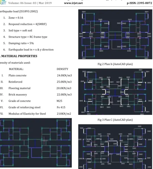
Fig 2 Plan b (AutoCAD plan)
Fig 3 Plan C (AutoCAD plan)
© 2019, IRJET | Impact Factor value: 7.211 | ISO 9001:2008 Certified Journal | Page 4855
4. RESULT
Chart -1: shear wall earthquake load +x
Chart -2: shear wall earthquake load +Z
Chart -3: shear wall wind load +Z
Chart -4: shear wall wind load +X
Chart -5: shear wall live load
© 2019, IRJET | Impact Factor value: 7.211 | ISO 9001:2008 Certified Journal | Page 4856
Chart -7: dead loadChart -8: bending moment for EQ load
Chart -9: bending moment for wind load
Chart -10: Axial force for EQ load
5. CONCLUSIONS
The building with shear wall has more earthquake resistance compared to building without shear wall.
There is no variation on wind effect for with and without shear wall building.
There is small variation on bending moment and axial force for with and without shear wall.
The node displacements are more for Zone V
compared to Zone III for earth quake load.
The Axial forces are decreased with increasing structural height for all models. From above analysis, it is observed that in G+13 Storey building, constructing building with shear wall at corner (Model C) location gives minimum drift and minimum displacement.
From all the above analysis and design, it is observed that in G+13 Story building, constructing building with shear wall at center (Model C) is economical as compared with shear wall structure (Model D).
Size of members like column can be reduced economically in case of structure with shear wall as compared to the same structure without shear wall.
Variation in column size at different floors in Model 1 affects the storey drift while in case of Model 3 it does not affect the storey drift due to the presence of shear wall.
© 2019, IRJET | Impact Factor value: 7.211 | ISO 9001:2008 Certified Journal | Page 4857
Less obstruction will be there because of reducedsize of column and provision of shear wall.
As per analysis, it is concluded that displacement at different level in multistoried building with shear wall is comparatively lesser as compared to R.C.C. building Without Shear Wall.
6.
REFERENCES
[1] Professor, Anirudhha Banhatti, “Earthquake Behavior of RCC Building for Various Shear Wall Configurations” IRJET e-ISSN: 2395-0056
[2] Ashish S. Agrawal and S.D. Charkha, “Study of Optimizing Configuration of Multi-Storey Building Subjected to Lateral Loads by Changing Shear Wall Location" proceedings of international conference on advances in architecture and civil engineering (aarcv 2012), 21st – 23rd june 2012 287 paper id sam137, vol. 1
[3] Dr. P.S. Pajgade, “Design of Multistoried R.C.C. Buildings with and without Shear Walls”,July, 2014, ISSN: 2277-9655
[4] Anshuman. S, Dipendu Bhunia, Bhavin Ramjiyani, “Solution of Shear Wall Location in Multi-Storey Building” international journal of civil and structural engineering, volume 2, 2011