DOI: 10.4236/msa.2019.106032 Jun. 5, 2019 433 Materials Sciences and Applications
Microstructural Evolution of GGG 40
Spheroidal Graphite Cast Iron Alloy
Marwan Faisal
1, Eman El-Shenawy
2, Mohamed A. Taha
11Faculty of Engineering, Ain-Shams University, Cairo, Egypt
2Central Metallurgical Research and Development Institute (CMRDI), Cairo, Egypt
Abstract
Studying the thermo-mechanical behavior of ductile iron is necessary to de-velop the rolling process for ductile iron sheet/strip production, thus, ex-tending its application by replacing steel in several fields such as machine casing, constructional applications, etc. In order to predict the safe rolling conditions for producing sheets and strips, the thermo-mechanical behavior of a ductile iron alloy, with CE of 4.48, is studied by physical simulation of hot rolling process using Gleeble-3500 simulator. The test was conducted on specimens at a range of deformation temperatures from 800˚C to 950˚C while three different strain rates; namely 0.05, 0.1 and 0.5 s−1 were used. The results obtained, show minimum values of flow stresses at 850˚C. By increasing the deformation temperature up to 900˚C, the flow stresses increased to reach maximum values, beyond which the flow stress decreased again. A remarka-ble dynamic recrystallization is observed at the deformation temperatures of 850˚C and 800˚C with applied strain rates of 0.05 and 0.1 s−1. Gleeble test re-sults are correlated with microstructure observations on samples quenched at their deformation temperatures, where the changes in structure and graphite morphology are reported. The deformation process at high temperatures namely 950˚C and 900˚C result in changing the graphite shape from a sphe-roidal-like to a saucer-like shape. However, by decreasing the deformation temperature to 850˚C as well as 800˚C, graphite with lamellar shape is ob-served. As a conclusion, ductile iron could be successfully deformed without cracking at the applied conditions.
Keywords
Ductile Iron, Thermo-Mechanical Behavior, Gleeble-3500, Physical Simulation, Graphite Morphology
How to cite this paper: Faisal, M., El- Shenawy, E. and Taha, M.A. (2019) Effect of Deformation Parameters on Microstruc-tural Evolution of GGG 40 Spheroidal Gra-phite Cast Iron Alloy. Materials Sciences and Applications, 10, 433-450.
https://doi.org/10.4236/msa.2019.106032
Received: April 19, 2019 Accepted: June 2, 2019 Published: June 5, 2019
Copyright © 2019 by author(s) and Scientific Research Publishing Inc. This work is licensed under the Creative Commons Attribution International License (CC BY 4.0).
http://creativecommons.org/licenses/by/4.0/
DOI: 10.4236/msa.2019.106032 434 Materials Sciences and Applications ductile iron [2] [3], a different response to heat treatment is detected due to the high content of carbon and silicon in ductile iron. The graphite nodules or spheroids act as a carbon sink or a carbon source in ductile iron, thus playing a significant role in the treatment process [3] [4]. Moreover, ductile iron com-pelled a wide recognition as an economical choice for replacing steel parts for its high toughness [5]. It is so far used in bearing journals and automotive compo-nents, for its relatively lower cost than steel, high cast-ability and outstanding wear resistance [6].
Ductile iron has advantages due to the additional characteristics that can be customized for applications requiring corrosion resistance, low thermal expan-sions, vibration damping and lubricating surface [7] [8]. These properties are required in strips and sheets for several applications namely; machine casing and constructional applications. Thus, replacing steel sheets by ductile iron sheets is proposed as an interesting idea. Although ductile iron exhibits high ductility for the forming process, only a few researchers [9] [10] [11] [12] investigated the formability and the rolling behavior of ductile iron.
Samuel [13] investigated the phase transformation kinetics in ductile iron by using a Gleeble machine that was to estimate the CCT curve for 65-45-12 ductile iron. Moreover, Zaho[14] [15] [16] applied a new severe plastic deformation process on ductile iron and studied the graphite morphology after applying a hot compression test on ductile iron alloy. Recently, the hot deformation behavior and the graphite morphology of ductile iron were investigated using the physical simulation technique [6] [17] [18]. Additionally, the microstructural changes in pearlitic-ferritic matrix were reported by increasing the degree of hot plastic de-formation [19] [20]. Furthermore, Soliman [21] studied the transformation ki-netics of thermo-mechanically processed ductile iron alloys.
In the current work, thermo-mechanical behavior of a ductile iron alloy with carbon Equivalence (CE) of 4.48 wt% was studied by using Gleeble-3500 physi-cal simulator. By the aid of the physiphysi-cal simulation process, thermo-mechaniphysi-cal behavior and phase transformations during this process were highlighted. The data obtained from the physical simulation technique will be used in the rolling process to produce sheets and/or strips of ductile iron.
2. Experimental Procedures
2.1. Objective and Methodology
The objective of this research is to study the hot deformation behavior of ductile iron at different temperatures and strain rates. The methodology includes;
1) Dilation test in order to determine the critical phase transformation tem-peratures,
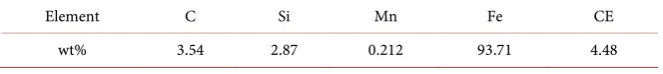
DOI: 10.4236/msa.2019.106032 435 Materials Sciences and Applications The chemical composition of the ductile iron alloy used in this work is given in
Table 1, where the carbon Equivalence (CE) of the alloy is 4.48. Specimens for
dilation test, heat treatment experiments, and thermo-mechanical processing were machined under cooling conditions.
2.3. Dilation Test
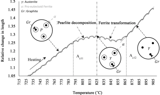
The objective of the dilation test was to determine the critical phase transforma-tion temperatures during heating (Ac11 and Ac12). The experiments are carried out on a cylindrical specimen with 4 mm in diameter and 30 mm in length by using differential dilatometer L76. Sheathed S-type thermocouple was spot welded on the specimen surface. Afterward, the specimen was placed horizon-tally between two Quartz stamps. The dilation test involved heating the speci-men to a temperature of 950˚C with a heating rate of 30˚C/min. Afterward, the specimen was soaked for 20 minutes and followed by air cooling to room tem-perature.
2.4. Heat Treatment Experiments
After determining the phase transformation temperatures (Ac11 and Ac12), four heat treatment schedules were applied on the ductile iron cubic specimens of 10 × 10 × 10 mm. The schedules involved heating the specimens (H-I, H-II, H-III and H-IV) in a muffle furnace to four different temperatures namely; 950˚C, 900˚C, 850˚C, and 800˚C respectively. Subsequently, the specimens were soaked for 20 minutes and followed by water-quenching to room temperature. These cycles were applied in order to identify the phases formed at the mentioned temperatures.
2.5. Physical Simulation Using Gleeble-3500
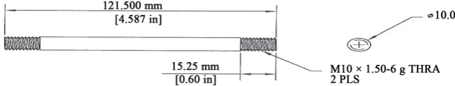
The hot deformation behavior of the ductile iron was studied using a computer servo-controlled Gleeble-3500 machine, which was adapted to apply uniaxial compression test. In accordance with that machine, the test was performed on cylindrical specimens with 10 mm in diameter and 120 mm long, as shown in
Figure 1. The axial compression was confined to the central specimen length of
30 mm, due to test specimen fixation as shown in Figure 2. K-type thermo
Table 1. Chemical composition of Ductile Iron used in this work.
Element C Si Mn Fe CE
DOI: 10.4236/msa.2019.106032 436 Materials Sciences and Applications Figure 1. Gleeble Test specimen used in the physical simulation.
Figure 2. Gleeble test specimen before and after deformation.
couple wire was spot-welded in the middle of the specimen in order to measure and control the specimen’s temperature. More details about the test are found elsewhere [22] [23].
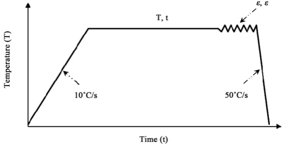
After identifying the phases evolved due to the heat treatment experiment, four thermo-mechanical schedules were designed in order to study the hot de-formation behavior of the ductile iron alloy at four different temperatures namely; 950˚C, 900˚C, 850˚C, and 800˚C with three different applied strain rates of 0.05, 0.1 and 0.5 s−1. The schedules involved heating the specimens with a heating rate of 10˚C/s to the desired deformation temperatures (T) and keeping for 20 minutes (see Table 2) to ensure structure homogenization and allow grain growth. Afterward, 39% deformation was applied on the specimens which are equivalent to a true strain of (−0.5 mm/mm) with three different applied strain rates (ε) of 0.05, 0.1 and 0.5 s−1 and followed by quenching to room tempera-ture with cooling rate of 50˚C/s, Figure 3.
2.6. Microstructure Investigation
In order to investigate the microstructural constituents, specimens were pre-pared by mechanical grinding followed by polishing up to 1 μm-grade diamond paste. The microstructures were examined by the aid of a light optical scope (LOM) after etching with Picral and/or 2% Nital. For superior micro-structural analysis and phase identification, the specimens were investigated by SEM and EDX analysis.
3. Results and Discussion
3.1. Dilation Results
[image:4.595.210.537.128.264.2]DOI: 10.4236/msa.2019.106032 437 Materials Sciences and Applications Figure 3. Schematic presentation of deformation schedules applied to ductile iron speci-mens.
Table 2. Deformation schedules of ductile iron specimens.
Schedule Deformation Temperature (T) Soaking Time (t) True Strain (ε) Strain Rate (ε)
I 950˚C 1200 s −0.5 mm/mm
0.05 s−1
0.1 s−1
0.5 s−1
II 900˚C 1200 s −0.5 mm/mm
0.05 s−1
0.1 s−1
0.5 s−1
III 850˚C 1200 s −0.5 mm/mm
0.05 s−1
0.1 s−1
0.5 s−1
IV 800˚C 1200 s −0.5 mm/mm
0.05 s−1
0.1 s−1
0.5 s−1
[image:5.595.209.540.298.506.2]DOI: 10.4236/msa.2019.106032 438 Materials Sciences and Applications Figure 4. Enlarged part from (Relative change in length-Temperature) during the heating of ductile iron specimen.
3.2. Heat Treatment Results
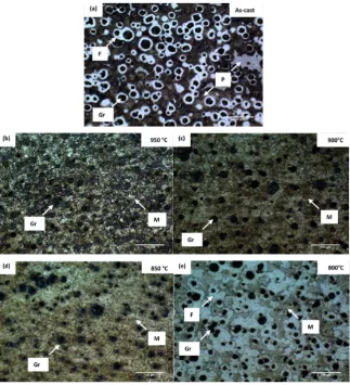
The as-cast specimen which consists of the pearlitic-ferritic matrix is given in
Figure 5(a). The observed microstructures of H-I, H-II, and H-III specimens
aregraphite nodules embedded in martensitic colonies, Figures 5(b)-(d) respec-tively. Thus, the austenite phase is formed at the mentioned temperatures be-fore quenching the specimens to room temperatures. While in H-IV specimen,
Figure 5(e), the obtained microstructure is martensite and pro-eutectoid
fer-rite surrounding the graphite nodules. That is due to the heating of H-IV spe-cimen in the inter-critical annealing region which results in the growth of the pro-eutectoid ferrite as well as the formation of the austenite. Later, the austenite is transformed to martensite after quenching H-IV specimen to room tempera-ture.
3.3. Physical Simulation Results
3.3.1. Flow Stresses during the Thermo-Mechanical Processing
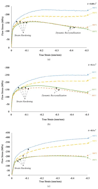
The effect of the deformation temperatures on the mechanical behavior of the ductile iron alloy with applied strain rates of 0.05, 0.1 and 0.5 s−1 is shown in
Figures 6(a)-(c) respectively. The minimum values of flow stresses are observed
during the deformation of the ductile iron at 850˚C. However, the flow stresses increased to reach the maximum values by increasing the deformation tempera-ture up to 900˚C, beyond which the flow stresses decrease again. It is clearly ob-served that the thermo-mechanical behavior of the ductile iron alloy is nearly the same as the deformation temperatures 850˚C and 800˚C. Moreover, a remarka-ble dynamic recrystallization is observed at deformation temperatures of 850˚C and 800˚C with applied strain rates of 0.05 and 0.1 s−1.
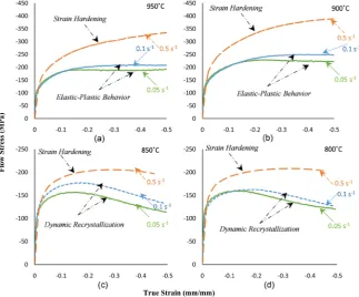
Figure 7 shows the effect of the applied strain rate on the thermo-mechanical
DOI: 10.4236/msa.2019.106032 439 Materials Sciences and Applications Figure 5. Microstructures of as-cast, H-I, H-II, H-III and H-IV specimens respectively.
proportional to the strain rate, as by increasing the strain rate, the flow stress values of the alloy increase at the same deformation temperature. Anelastic- plastic flow behavior is observed by deforming the ductile iron alloy at 950˚C and 900˚C with applied strain rates of 0.05 and 0.1 s−1. While by increasing the strain rate to 0.5 s−1, a strain hardening behavior is detected. In contrast, a dy-namic recrystallization occurred by applying strain rates of 0.05 and 0.1 s−1 at deformation temperatures of 850˚C and 800˚C.
3.3.2. Microstructure Evolution
DOI: 10.4236/msa.2019.106032 440 Materials Sciences and Applications (a)
(b)
[image:8.595.209.537.66.699.2](c)
DOI: 10.4236/msa.2019.106032 441 Materials Sciences and Applications Figure 7. The effect of the applied strain rates on the thermo-mechanical behavior of the ductile iron alloy at deformation temperatures of (a) 950˚C; (b) 900˚C; (c) 850˚C and (d) 800˚C.
formed by heating at such temperatures above Ac12 did not change upon de-formation. The carbon content in the austenitic matrix decreases by decreasing the temperature, [25]i.e. at the deformation temperature of 900˚C, the amount of dissolved carbon in the austenitic matrix is less than that at 950˚C. Thus upon quenching the specimens, the pearlite phase is formed around the graphite no-dules, due to the diffusion of carbon atoms from the austenite phase to the gra-phite nodules [26].
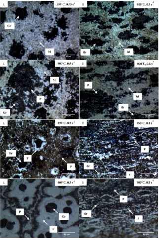
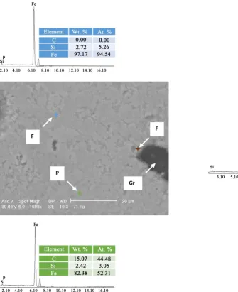
DOI: 10.4236/msa.2019.106032 442 Materials Sciences and Applications Figure 8. The revealed microstructure of the deformed specimens at different conditions
in direction perpendicular (⊥)& parallel (∥) to the applied force.
rate of 0.05 s−1, a higher Si content of 3.33 wt% was detected in the pro-eutectoid ferrite within the matrix, Figure 10.
DOI: 10.4236/msa.2019.106032 443 Materials Sciences and Applications Figure 9. SEM and EDX analysis of the deformed specimen at 850˚C with an applied strain rate of 0.05 s−1.
observed by varying deformation temperature, Figure 11. With decreasing the deformation temperature, the graphite volume fraction increases as more gra-phite has been formed.
3.3.3. Thermo-Mechanical Behavior and Microstructure
Figure 12 schematically correlates the microstructure with the thermo-mecha-
nical behavior of the ductile iron specimens at different temperatures with an applied strain rate of 0.05 s−1. By decreasing the deformation temperature from 950˚C to 900˚C, the flow stress values increase at the same applied strain rate. The microstructure of the ductile iron prior to the deformation process at the mentioned temperatures is graphite nodules embedded in an austenitic matrix. Thus, deforming the ductile iron at 950˚C and 900˚C is mainly deforming the austenite phase (single phase deformation).
DOI: 10.4236/msa.2019.106032 444 Materials Sciences and Applications Figure 10. SEM and EDX analysis of the deformed specimen at 800˚C with an applied strain rate of 0.05 s−1.
[image:12.595.215.533.442.700.2]DOI: 10.4236/msa.2019.106032 445 Materials Sciences and Applications Figure 12. Flow Stress-True strain curves obtained by deforming the ductile iron at an applied strain rate of 0.05 s−1, where the
schematic presentation of the evolved microstructures before and after deformation were superimposed.
DOI: 10.4236/msa.2019.106032 446 Materials Sciences and Applications atures. Moreover, the high amount of silicon is found at the interface of the gra-phite nodules [25]. Hence, a barrier of high silicon content in the pro-eutectoid ferrite is formed and restricted the role of the graphite nodules as a carbon sink. Therefore, the austenite phase is isolated by the stabilized pro-eutectoid ferrite. Nevertheless, the carbon atoms favor diffusing from the austenite phase as the temperature decreased upon further deformation. However, the formed barrier hindered and/or dropped the diffusion rate of the carbon atoms to the graphite nodules. In addition, the increase of the dislocation densities by further defor-mation results in a dynamic recrystallization to eliminate the defects and become thermodynamically stable [27]. Also, it is suggested that the graphite nodules at high temperatures are cheese-liked, while at low temperature the graphite no-dules become harder. The occurrence of dynamic recrystallization is due to the pileup of dislocations [16].
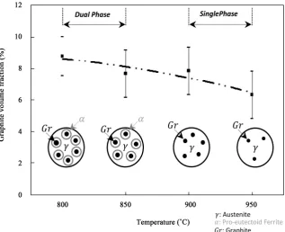
Moreover, due to the plastic deformation of the specimens, the graphite no-dules shape is changed in a direction parallel to the applied force in comparison with the as-cast structure. The deformation process at high temperatures namely 950˚C and 900˚C results in changing the graphite shape from a spheroidal-like to a saucer-like shape. However, by decreasing the deformation temperature to 850˚C as well as 800˚C, graphite with lamellar shape is observed. Therefore, the austenitic matrix containing graphite nodules are in the shape of saucers. How-ever, after the deformation process, the graphite nodules become lamellar gra-phite surrounded by the pro-eutectoid ferrite phase. Similar gragra-phite shape is also reported elsewhere [6]. Hence, the matrix surrounding the graphite nodules as well as the deformation temperature strongly affect the final shape of graphite nodules after the deformation process, as schematically presented in Figure 12. The effect of the deformation temperature on the graphite volume fraction is compared to other work [6], Figure 13. The graphite volume fraction increases by decreasing the deformation temperature of the ductile iron with CE = 4.48. However, it is detected—in ductile iron with CE = 4.8—that the general trend of the graphite volume fraction decreases within [800 - 950]˚C by decreasing the deformation temperature. The cooling rate of the specimens with CE = 4.8 was slow (air cooled to room temperature) which might have promoted time for the diffusion of carbon atoms to graphite nodules upon cooling resulting in in-creasing the graphite volume fraction.
DOI: 10.4236/msa.2019.106032 447 Materials Sciences and Applications Figure 13. The effect of the deformation temperature on the graphite volume fractionin comparison with other work.
Figure 14. The effect of deformation temperature on the Elastic modulus of the ductile iron at applied strain rates of 0.05, 0.1 and 0.5 s−1.
[image:15.595.214.533.305.498.2]DOI: 10.4236/msa.2019.106032 448 Materials Sciences and Applications Figure 15. The effect of deformation temperature on the strain hardening exponent of the ductile iron at applied strain rates of 0.05, 0.1 and 0.5 s−1.
4. Conclusions
Thermo-mechanical simulation using Gleeble System conducted on a ductile iron alloy (CE of 4.48, and Ac11 and Ac12 of 792˚C and 867˚C respectively, as detected by dilation test) applying strain rates of 0.05, 0.1, and 0.5 s−1 and varying deformation temperatures causes variation in structure and flow stress behavior as follows:
The microstructure at deformation temperatures of 950˚C, consists of a fully martensitic matrix surrounding the graphite phase. At lower temperature of 900˚C, graphite nodules embedded in a martensitic-pearlitic matrix is de-tected. At these temperatures, the graphite shape changes from spheroid-al-like to saucer-like shape.
The microstructure at the lower deformation temperatures of 850˚C and 800˚C, below Ac12, 867˚C, consists of pearlite and pro-eutectoid ferrite sur-rounding the graphite nodules were observed in the deformed specimens, in-dicating austenitic-ferritic matrix. Formation of pro-eutectoid ferrite contri-butes to increasing graphite volume fraction as the carbon atoms diffuse from the austenitic matrix to the graphite nodules during the ferrite forma-tion. Within the matrix and far from the graphite nodules, fine pro-eutectoid ferrite grains were also observed. At these temperatures, the graphite shape is lamellar.
DOI: 10.4236/msa.2019.106032 449 Materials Sciences and Applications per.
References
[1] Di Cocco, V., Iacoviello, D., Iacoviello, F. and Rossi, A. (2015) Graphite Nodules In-fluence on DCIs Mechanical Properties: Experimental and Numerical Investigation.
Procedia Engineering, 109, 135-143. https://doi.org/10.1016/j.proeng.2015.06.223
[2] Hsu, C.-H. and Chuang, T.-L. (2001) Influence of Stepped Austempering Process on the Fracture Toughness of Austempered Ductile Iron. Metallurgical and Mate-rials Transactions A, 32, 2509-2514. https://doi.org/10.1007/s11661-001-0040-y
[3] Rehder, J. (1965) Critical Temperature Heat Treatment of Cast Irons. Foundry, June.
[4] Norman, V. and Calmunger, M. (2019) On the Micro- and Macroscopic Elastoplas-tic Deformation Behavior of Cast Iron When Subjected to Cyclic Loading. Interna-tional Journal of Plasticity, 115, 200-215. https://doi.org/10.1016/j.ijplas.2018.11.019
[5] Labrecque, C. and Gagne, M. (1998) Ductile Iron: Fifty Years of Continuous De-velopment. Canadian Metallurgical Quarterly, 37, 343-378.
https://doi.org/10.1179/cmq.1998.37.5.343
[6] Qi, K., Yu, F., Bai, F., Yan, Z., Wang, Z. and Li, T. (2009) Research on the Hot De-formation Behavior and Graphite Morphology of Spheroidal Graphite Cast Iron at High Strain Rate. Materials & Design, 30, 4511-4515.
https://doi.org/10.1016/j.matdes.2009.05.019
[7] Sidjanin, L., Smallman, R.E. and Young, J.M. (1994) Electron Microstructure and Mechanical Properties of Silicon and Aluminum Ductile Irons. Acta Metallurgica et Materialia, 42, 3149-3156. https://doi.org/10.1016/0956-7151(94)90412-X
[8] Ghaderi, A.R., Nili Ahmadabadi, M. and Ghasemi, H.M. (2003) Effect of Graphite Morphologies on the Tribological Behavior of Austempered Cast Iron. Wear, 255, 410-416. https://doi.org/10.1016/S0043-1648(03)00156-X
[9] Bača, J. and Chaus, A.S. (2004) Effect of Plastic Deformation on the Structure and Properties of Cast Iron with Globular Graphite. Metal Science and Heat Treatment, 46, 188-191. https://doi.org/10.1023/B:MSAT.0000043098.43295.94
[10] Lyakishev, N.P. and Shcherbedinskii, G.V. (2001) Hot Plastic Deformation of High-Strength Cast Iron. Metal Science and Heat Treatment, 43, 421-422.
https://doi.org/10.1023/A:1014883023922
[11] El-Bitar, T. and El-Banna, E. (1997) Contribution of Forming Parameters on the Properties of Hot-Rolled Ductile Cast Iron Alloys. Materials Letters, 31, 145-150.
https://doi.org/10.1016/S0167-577X(96)00254-6
[12] Martínez, R.G., Torre, U., Ebel, A., Lacaze, J. and Sertucha, J. (2018) Effects of High Silicon Contents on Graphite Morphology and Room Temperature Mechanical Properties of As-Cast Ferritic Ductile Cast Irons. Part II. Mechanical Properties.
Materials Science & Engineering A, 712, 803-811.
DOI: 10.4236/msa.2019.106032 450 Materials Sciences and Applications
for Spheroidal Cast Iron. Materials Letters, 58, 2335-2339.
https://doi.org/10.1016/j.matlet.2004.01.034
[15] Zhao, X., Jing, T., Gao, Y., Qiao, G., Zhou, J. and Wang, W. (2004) Morphology of Graphite in Hot-Compressed Nodular Iron. Journal of Materials Science, 39, 6093- 6096. https://doi.org/10.1023/B:JMSC.0000041709.60100.56
[16] Zhao, X., Yang, X.-L. and Jing, T.-F. (2011) Processing Maps for Use in Hot Work-ing of Ductile Iron. Journal of Iron and Steel Research, International, 18, 48-51.
https://doi.org/10.1016/S1006-706X(11)60049-6
[17] Le Mercier, K., Watremez, M., Guerin, J.-D., Fouillaud, L. and Dubar, L. (2013) Thermo-Mechanical Behavior of Spheroidal Graphite Iron in the Austenitic Phase. Congrès Français de Mécanique, 21; 2013; Bordeaux.
[18] Holst, A., Buchwalder, A., Hollmann, P. and Zenker, R. (2019) Influence of Cooling Rate on the Microstructural Features of a Remelted White Solidified Cast Iron Sur-face and Its Effects on Nitriding Behavior. Journal of Materials Processing Tech-nology, 271, 377-383. https://doi.org/10.1016/j.jmatprotec.2019.04.004
[19] Chaus, A.S. (2014) Effect of Room-Temperature Compression on Microstructure of Ductile Cast Iron Subjected to Hot Plastic Deformation. The Physics of Metals and Metallography, 115, 672-681. https://doi.org/10.1134/S0031918X14040048
[20] Chaus, A.S., Sojka, J. and Pokrovskii, A.I. (2013) Effect of Hot Plastic Deformation on Microstructural Changes in Cast Iron with Globular Graphite. The Physics of Metals and Metallography, 114, 85-94. https://doi.org/10.1134/S0031918X13010031
[21] Soliman, M., Nofal, A. and Palkowski, H. (2015) Alloy and Process Design of Thermo-Mechanically Processed Multiphase Ductile Iron. Materials & Design, 87, 450-465. https://doi.org/10.1016/j.matdes.2015.07.159
[22] Faisal, M., El-Shenawy, E. and Taha, M.A. (2017) Thermomechanical Testing of GGG 40 Spheroidal Graphite Cast Iron Alloy. Materials Sciences and Applications, 8, 273-280. https://doi.org/10.4236/msa.2017.83019
[23] El-Bitar, T., El-Shenawy, E. and El-Meligy, M. (2017) Physical Simulation of Ther-mo-Mechanical Processing of Ferritic-Bainitic Dual Phase (FBDP) Steel. Materials Science Forum, 879, 495-501.
https://doi.org/10.4028/www.scientific.net/MSF.879.495
[24] Samuel, C.J.P. (2010) The Effect of Copper on the Eutectoid Transformation in Ductile Iron. The University of Alabama, Tuscaloosa.
[25] Trepczyńska-Łent, M. and Dymski, S. (2005) The Outlook upon Austenitizing the Matrix of Ductile Iron. Archives of Foundry, 5, 353-364.
[26] Cavallini, M., Di Cocco, V., Iacoviello, F. and Iacoviello, D. (2011) Ductile Irons Damaging Micromechanisms: Graphite Nodules Role Investigated by Means of Image Processing Procedures. Convegno IGF XXI Cassino 2011.
[27] Huang, K. and Logé, R.E. (2016) A Review of Dynamic Recrystallization Phenome-na in Metallic Materials. Materials & Design, 111, 548-574.
https://doi.org/10.1016/j.matdes.2016.09.012
[28] Kilicli, V. and Erdogan, M. (2008) The Strain-Hardening Behavior of Partially Aus-tenitized and the Austempered Ductile Irons with Dual Matrix Structures. Journal of Materials Engineering and Performance, 17, 240-249.