Submitted Manuscript: Confidential
New models for energy beam machining enable accurate generation of freeforms
D. Axinte1*, J. Billingham2, A. Bilbao Guillerna11Faculty of Engineering, University of Nottingham, UK. 2School of Mathematical Sciences, University of Nottingham, UK.
*Corresponding author: [email protected]
Abstract: We demonstrate that, despite differences in their nature, many energy beam controlled-depth machining processes (e.g. waterjet, pulsed laser, focused ion beam) can be modelled using the same mathematical framework – a partial differential evolution equation that requires only simple calibrations to capture the physics of each process. The inverse problem can be solved efficiently through numerical solution of the adjoint problem, and leads to beam paths that generate prescribed three-dimensional features with minimal error. The viability of this modelling approach has been demonstrated by generating accurate freeform surfaces using three processes that operate at very different length scales and with different physical principles for material removal: waterjet, pulsed laser and focused ion beam machining. Our approach can be used to accurately machine materials that are hard to process by other means for scalable applications in a wide variety of industries.
One-Sentence Summary: A generic mathematical model is used to determine the beam paths for various energy beam machining processes to generate a variety of freeform surfaces.
Energy beam (EB) processes, such as abrasive waterjet (AWJ), pulsed laser ablation (PLA) and focused ion beam (FIB), can be used for controlled-depth machining (material removal) of difficult-to-process materials. This enables the generation of complex freeform surfaces for various applications ranging from medical and Micro-Electro-Mechanical Systems (MEMS) to aerospace and defence applications. These EB machining methods provide a set of complementary capabilities:
(i) Length scale (minimum beam diameter); AWJ – macro/meso (>120μm); PLA – meso/pseudo-micro (>5μm); FIB - meso/pseudo-micro-nano (>10nm);
(ii) Productivity (material removal rate); AWJ - high (around 3000mm3/min); PLA - medium (0.08-80 x 107 μm3/s); FIB – low/very low (0.02-3 x 10⁻² μm3/s);
(iii) Versatility: AWJ - any material; PLA - dependent on the laser absorption coefficient of the material; FIB - need vacuum;
(iv) Surface quality (average absolute height deviations): AWJ - rough (Ra>3.6μm); PLA - fine (Ra>0.6μm); FIB - ultra-fine (Ra<<0.6μm).
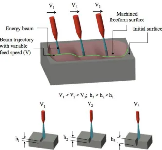
Fig. 1: Generic representation of EB controlled-depth machining, variation of the footprint with beam exposure time and its relative position to the target surface.
Different EB processes use different mechanisms to remove material: mechanical erosion (AWJ), melting and vaporisation (PLA), energy/momentum transfer (FIB). In previous studies, these processes have therefore been treated separately from both an experimental and a modelling point-of-view. In particular, some attempts have been made to model the generation of both single and superposed footprints, using physics-based models (1-3) and numerical models (4-6). These approaches usually involve strong simplifying assumptions and difficult calibration procedures, which leads to long computation times, making them impossible to use in practice for the control of machine tools that can generate complex freeforms. Moreover, since these models attempt to capture the detailed physics of each specific removal process, they are not generic, i.e. they do not lead to methods that are applicable for a wide range of EB processes in a variety of setups and applications.
In contrast, we have developed a simpler modelling approach that can predict the geometry of the machined footprint for, theoretically, any EB machining process (7, 8). To account for the specific material removal mechanisms by a particular EB process, a set of simple experimental calibrations is carried out and specific removal rate functions identified. This allows us to unify the modelling of these processes into a common mathematical framework based on a partial differential evolution equation for the workpiece surface. This equation has a straightforward structure that respects the basic physics of the process, but which is simple enough that it can be accurately calibrated using a few initial experiments. Once this has been done, single and superposed footprint profiles can be determined for any kinematic EB parameters, i.e. path, exposure time along the path and angle of incidence of the EB. This is the direct problem in EB machining. If the path of the EB is selected based either on the intuition and experience of the end-user (craftsmanship) or on trial and error, there can be a large discrepancy between the actual machined surface and the freeform surface that is the required outcome of the EB process.
depending on the desired aspect ratio of the freeform, whilst maintaining the original stand-off distance with each successive layer.
Despite the importance of the inverse problem in the generation of freeform surfaces using time-dependent material removal processes, very few investigations on this topic have been reported. Some approaches simply vary the exposure time of the beam on each pixel of the required surface (9, 10); this is simply the leading order approximation to the necessary strategy when the radius of the beam is small compared to the size of the feature that is being etched. However, this takes account of neither nonlinear effects, the detailed shape of the footprint nor the effect of overlapping beam paths. Whilst it is a plausible starting strategy, particularly for FIB, it is not sufficient for other EB processes or even, in all situations, for FIB. In addition, a Fourier convolution approach to the linearized version of this problem, which does not explicitly take the path of the beam into account, has been studied for abrasive jet micromachining, fluid jet polishing and ion beam figuring in (17-20). If the features that need to be machined are comparable to the size of the beam, a more sophisticated approach is needed.
Some reports on the inverse problem for other time-dependent processes include: electro-chemical machining
(11), where the tool/electrode works in tangential mode to envelope the required surface; electro-discharge machining (12) where the electrode copies the geometry of the final surface, so a solution of the inverse problem is not required. We recently reported on a solution of the inverse problem in AWJ, working in the linear erosion regime to minimise errors in the generation of simple 2D shapes (13).
Our research aims to present a unified method of modelling EB machining that allows us to solve the inverse problem, so that highly accurate freeforms can be generated independent of the physics that governs the material removal process. Our approach is simple, efficient and requires only modest computing power to produce the required beam paths and exposure times. We have validated this approach using three different EB machining processes: abrasive waterjet (AWJ), pulsed laser ablation (PLA) and focused ion beam (FIB).
The basis of our mathematical model of EB processes is that the boundary of the workpiece evolves as a function of exposure time under the action of the beam. In particular, only the part of the surface that is beneath the beam changes at any instant, and the only explicit spatial dependence of the rate of material removal is given by a removal rate function, 𝐸(𝑟), which depends upon the distance from the centre of the beam, 𝑟, alone. We also assume that the physics of the removal process can be decomposed into a set of multiplicative functions, which variously characterise the slope dependence, depth dependence and beam velocity (EB exposure time) dependence of the rate at which material is removed. The number and form of these functions vary between processes, but for each process there is a simple calibration procedure (9, 14).
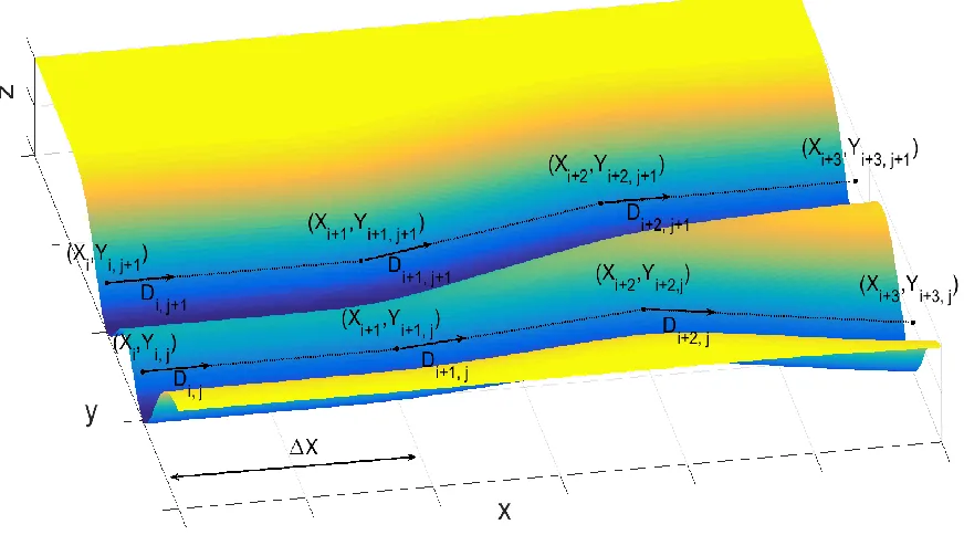
We work in a Cartesian coordinate system, (𝑥, 𝑦, 𝑧), with the axis of the beam parallel to the 𝑧-axis (Fig. 2). We will assume that the axis of the beam retains this orientation during the whole machining process. We also assume that the workpiece has an initially flat boundary, given by 𝑧 = 𝑍(𝑥, 𝑦, 𝑡), with 𝑍(𝑥, 𝑦, 0) = 0. The evolution equation is
𝜕𝑍
𝜕𝑡 = −𝐸(𝑟(𝑡; 𝒖))𝑓1(∇𝑍)𝑓2(|𝑽|)𝑓3(𝑍),
Fig. 2: Notation used in parameterising the beam paths.
We briefly summarize how the functions 𝑓1, 𝑓2and 𝑓3 are calibrated for each of the three EB processes we have studied. For more details see (7, 9).
For AWJ, 𝑓2 = 𝑓3 = 1 (only the angle of incidence on the surface is found to nonlinearly affect the process), and the calibration is in two stages. Firstly, the removal rate function, 𝐸(𝑟), is determined from measurements of a straight, shallow trench machined with constant feedspeed, for which 𝑓1 ≈ 1. Under this approximation, the model is linear, and 𝐸(𝑟) can be directly related to the profile across the trench (averaged along the trench to minimise the effect of process noise) through a simple integral. Secondly, the function 𝑓1(∇𝑍) is determined by machining a straight trench along which the beam speed increases linearly. A quadratic function of the angle of incidence is found to give excellent results. For PLA, 𝑓1 = 𝑓3 = 1 (only the feedspeed is found to nonlinearly affect the process), and the calibration is again in two stages. Firstly, the removal rate function, 𝐸(𝑟), is calibrated in the same manner as for AWJ. Secondly, the function 𝑓2(|𝑽|) is determined by machining a straight trench along which the beam speed increases linearly. For PLA, a linear function of the exposure time is the appropriate functional form.
For FIB, 𝑓2 = 1 (both angle of incidence and machined depth, but not beam speed, affect the process). The functional form of 𝑓1(∇𝑍) is well-known for FIB, (15,16), and is characterised by two parameters. The function 𝑓3(𝑍) is introduced to account for the way that FIB merely damages the surface when the beam speed is large, which appears as a skin effect in the results. The function 𝑓3(𝑍) is chosen to be an exponential that tends to one as 𝑍 → −∞ (away from the skin), which accounts for this effect and introduces a further two parameters. Because of this skin effect, the simple procedure that allows 𝐸(𝑟) to be calibrated in AWJ and PLA does not work. However, 𝐸(𝑟) is found experimentally to be close to Gaussian, and can therefore be characterised by two parameters. The model parameters can easily be calibrated by machining straight trenches at several beam speeds and measuring the averaged profile across each trench.
𝜕𝑍
𝜕𝑠 = −𝐷(𝑠; 𝒖)𝐸(𝑟(𝑠; 𝒖))𝑓1(∇𝑍)𝑓2(𝐷−1)𝑓3(𝑍),
where 𝐷 ≡ |𝑽|−1 is the exposure time.
For given beam path parameters, 𝒖, the forward problem is to integrate the evolution equation forward as the beam moves along its path until 𝑠 = 𝑆(𝒖), where 𝑆(𝒖) is the total arclength of the beam path, and determine the final etched surface, 𝑍(𝑥, 𝑦, 𝑆; 𝒖).
For given required final etched surface, 𝑍𝑇(𝑥, 𝑦), the inverse problem is to find beam path control parameters, 𝒖, such that 𝑍(𝑥, 𝑦, 𝑆(𝒖); 𝒖) = 𝑍𝑇(𝑥, 𝑦). Partial differential equation constrained inverse
problems like this, where there are finitely many parameters, 𝒖, and an infinite dimensional target, 𝑍𝑇(𝑥, 𝑦), need to be formulated as an optimization problem. We define the cost function, 𝐽(𝒖) ≡ ‖𝑍(𝑥, 𝑦, 𝑆(𝒖); 𝒖) −
𝑍𝑇(𝑥, 𝑦)‖2, and seek to minimise it over the space of possible control parameters, 𝒖.
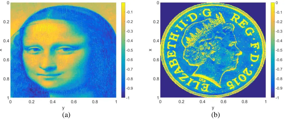
For a complex freeform surface (we will use the Mona Lisa and the British penny – Fig. 3) it is likely that the path of the beam that optimally solves the inverse problem is itself complex. However, practical constraints imposed by machine dynamics mean that beam paths with significant high frequency components cannot be used (13). One approach to this problem is to use simple raster paths, i.e. parallel beam movements with constant overlapping. For AWJ, paths more complex than this are almost impossible to control due to the complexity and inertial mass of the machine, but for PLA and FIB, the control and dynamic characteristics of the machines is such that more complex paths can be used. We have chosen to use close to raster (small deviations from parallel) paths to demonstrate our solution of the inverse problem since they are a good compromise between complexity and machinability.
On each of the Np passes there are Nu control points, through which the beam passes in a piecewise linear
manner. At each of these points, (𝑋𝑖,𝑗, 𝑌𝑖,𝑗), the exposure time is 𝐷𝑖,𝑗. This exposure time is also linearly interpolated between control points. This fully specifies the beam path. The distance between consecutive points is chosen to be constant in the 𝑥-direction, so that
𝑋𝑖,𝑗 = 𝑋𝑖−1,𝑗+ ∆𝑋 for 1 < 𝑖 ≤ 𝑁𝑢 − 1 .
The beam path parameter vector, u, is therefore composed of the exposure time at each control point and (unless straight raster paths are used) the 𝑦-coordinate of each control point, so that
𝒖 = (𝑌0,0, 𝐷0,0, 𝑌1,0, 𝐷1,0, 𝑌2,0, 𝐷2,0,… , 𝑌𝑁𝑢−1,𝑁𝑝−1, 𝐷𝑁𝑢−1,𝑁𝑝−1).
The first subscript, 1 ≤ 𝑖 ≤ 𝑁𝑢, denotes the 𝑖th control point for each raster pass, and the second subscript,
1 ≤ 𝑗 ≤ 𝑁𝑝, indicates the 𝑗th pass, so there are 2𝑁𝑝𝑁𝑢 control parameters in the most general case.
The forward problem is
𝜕𝑍
𝜕𝑠 = −𝐷(𝑠; 𝒖)𝐸(𝑟(𝑠; 𝒖))𝑓1(∇𝑍)𝑓2(𝐷)𝑓3(𝑍),
subject to 𝑍(𝑥, 𝑦, 0; 𝒖) = 0, for 0 ≤ 𝑠 ≤ 𝑆(𝒖). For given 𝒖, and hence a given beam path and exposure time as a function of arc-length, a simple, central finite difference scheme with explicit Euler arc-length stepping and a uniform Cartesian grid is sufficient to accurately compute 𝑍(𝑥, 𝑦, 𝑆(𝒖); 𝒖), the final etched surface, and hence the cost function,
𝐽(𝒖) ≡ ‖𝑍(𝑥, 𝑦, 𝑆(𝒖); 𝒖) − 𝑍𝑇(𝑥, 𝑦)‖2. The inverse problem, namely to find a set of control parameters, 𝒖∗, such that
𝐽(𝒖∗) ≤ 𝐽(𝒖) ∀𝒖 ∈ 𝑈,
simple gradient-based approach is able to locate a local minimum of 𝐽(𝒖), which is in good agreement with the target surface, although we cannot guarantee that this is a global minimum.
In order to implement gradient-based optimisation, we need an efficient way to calculate the gradient matrix,
𝜕𝐽 𝜕𝒖⁄ . Since there are typically several thousand control parameters in 𝒖, the obvious, finite difference approach is prohibitively expensive. Instead, we solve the discrete adjoint to the finite difference solver for the forward problem to efficiently evaluate the gradient. The uniform grid, explicit Euler finite difference approach is simple enough that we can calculate the adjoint finite difference scheme by hand. This consists of another evolution problem that must be integrated backward along the beam path. This calculation is of comparable computational complexity to the calculation of 𝐽(𝒖) in theforward problem, and gives us a very efficient means of calculating the gradient at each step of the optimization.
We have used this methodology to generate freeforms on various materials using AWJ, PLA and FIB as EB machining processes (see the Supplementary Material for more details). We will illustrate our results using complex freeforms, namely the Mona Lisa (a smooth surface), Fig. 3a, and the British Penny coin (a surface with various sharp edges with different orientations), Fig. 3b.
[image:6.612.80.537.278.469.2](a) (b)
Fig. 3: Normalised target smooth (a) and sharp edged (b) surfaces to be generated by EB machining
For each surface we show results with straight raster beam paths and, in order to demonstrate that we can obtain significantly better results for surfaces with sharp edges, we also used non-straight raster paths for the Penny coin. Note also that for AWJ we were able to use only straight paths due to practical constraints imposed by machine dynamics, so we only present results for the Mona Lisa.
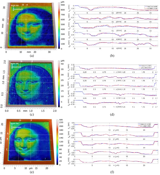
Figure 4 shows the Mona Lisa, a typical smooth surface, generated by (a) AWJ, (b) PLA, (c) FIB using straight raster paths. The noise inherent in AWJ machining, due to the complex multi-phase turbulent fluid flow in the jet, and its interactions with the target surface as well as the dynamics of the machine, leads to significantly less accurate freeform generation with less high frequency content (small scale features). In addition, deviations from the required profiles on different cross sections (A, B, C, D, E) are presented for each process in Fig. 4d, e, f.
detail to the required surface than that machined using either AWJ and FIB (see Fig. 4e and f). This is due, not to error in the machined surfaces themselves, but to the fact that our model for FIB is inherently nonlinear due to the skin effect, which means that our algorithm produces simulated surfaces that are significantly less accurate for FIB than for PLA.
(a) (b)
(c) (d)
[image:7.612.48.576.111.688.2](e) (f)
Fig. 4: Typical smooth surfaces generated by AWJ (a), PLA (c) and FIB (e) machining and comparisons between experimental and simulated profiles on various cross sections (A, B, C, D, E) for the three EB
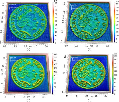
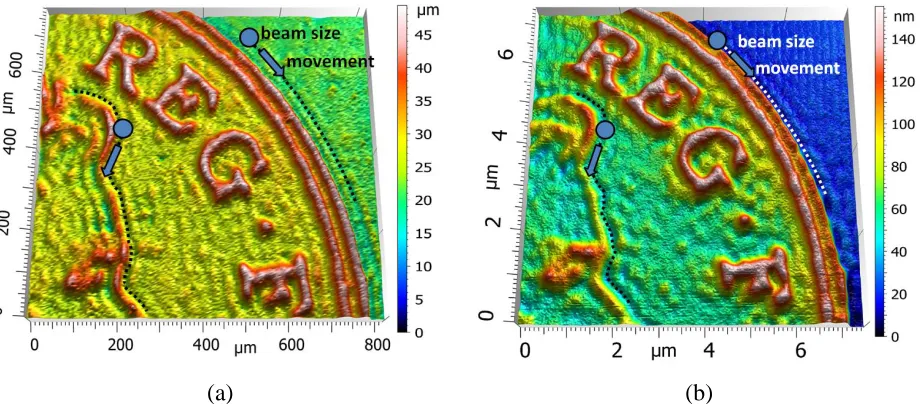
Figure 5 shows the British Penny, a typical surface with sharp edges at different orientations, generated by (a) PLA and (b) FIB using straight raster paths and in (c) and (d) using non-straight raster paths. It clear that the non-straight paths are able to capture the sharpness of the various edges more accurately, which demonstrates the utility of our approach. Details of the surfaces generated by non-straight passes are presented in Fig. 6, where it can be clearly observed that the beam follows the edges of the freeform, thus resulting in better definition of the surface.
(a) (b)
(c) (d)
(a) (b)
Fig. 6: Detail of the surfaces with sharp edges generated by PLA (a) and FIB (b) with non-straight beam passes. Note that the beam follows the sharp edges.
We have developed a simple generic modelling approach and algorithms for the inverse problem to generate freeform surfaces using different EB machining processes and various workpiece target materials. This modelling approach is able to embed the physics of the diverse range of material removal mechanisms encountered in EB processing, using simple experimental calibration. The accuracy of the approach has been demonstrated by low (AWJ – 10-20%, PLA – 6-8 %, FIB – 4-6%) average relative errors from the required surfaces.
References:
1. M. EITobgy. E-G. Ng, M. A. Elbestawi, Modelling of Abrasive Waterjet Machining: A New Approach.
CIRP Ann.-Manuf. Techn. 54/1, 285-288 (2005).
2. H. D. Vora, S. Santhanakrishnan, S. P. Harimkar, S. K. S. Boetcher, N. B. Dahotre, One-dimensional multipulse laser machining of structural alumina: evolution of surface topography. Int. J. Adv. Manuf. Tech., 68/1, 69–83 (2013).
3. T. Ishitani, T. Ohnishi, Modeling of sputtering and redeposition in focused-ion-beam trench milling. J. Vac. Sci. Technol. A, 9, 3084–3089 (1991).
4. S. Anwar, D. A. Axinte, A. A. Becker, Finite element modelling of abrasive waterjet milled footprints.
J. Mater. Process. Tech., 213/2, 180-193 (2013).
5. J. Lee, J. Yoo, K. J. Lee, Numerical simulation of the nano-second pulsed laser ablation process based on the finite element thermal analysis. J. Mech. Sci. Technol., 28, 1797-1802 (2014).
6. M. F. Russo, Jr., M. Maazouz, L. A. Giannuzzi, C. Chandler, M. Utlaut, B. J. Garrison, Gallium-induced milling of silicon: A computational investigation of focused ion beams. Microsc. Microanal., 14, 315–320 (2008).
7. J. Billingham, C.B. Miron, D. A. Axinte, M. C. Kong, Mathematical modelling of abrasive waterjet footprints for arbitrarily moving jets: Part II - Overlapped single and multiple straight paths. Int. J. Mach. Tool Manuf., 68, 30-39 (2013).
8. G. Cadot, D.A. Axinte, J. Billingham, Continuous trench, pulsed laser ablation for micro-machining applications, Int. J. Mach. Tool Manuf., 107, 8–20 (2016).
[image:9.612.78.538.49.251.2]10. D. P. Adams, M. J. Vasile, Accurate focused ion beam sculpting of silicon using variable pixel dwell time approach. J. Vac. Sci. Technol. B, 24, 836–844 (2006).
11. P. Domanowski, Inverse problem of shaping by electrochemical generating machining. J. Mater. Process. Tech., 109/3, 347-353 (2001).
12. M. Kunieda, Reverse simulation of sinking EDM applicable to large curvatures. Prec. Eng., 36/2, 238– 243 (2012).
13. A. Bilbao-Guillerna, D. A. Axinte, J. Billingham, The linear inverse problem in energy beam processing with an application to abrasive waterjet machining. Int. J. Mach. Tool Manuf., 99, 34–42 (2015).
14. M. C. Kong, S. Anwar, J. Billingham, D. Axinte, Mathematical modelling of abrasive waterjet footprints for arbitrarily moving jets: Part I - single straight paths, Int. J. Mach. Tool Manuf., 53/1, 58-68 (2012).
15. X. Xu, Focused ion beam induced deposition and ion milling as a function of angle of ion incidence. J. Vac. Sci. Technol. B, 10/6, 1992, 2675-2680.
16. Y. Yamamura, Y. Itikawa, N. Itoh, Angular dependence of sputtering yields of monatomic solids. IPPJ-AM report 26, Nagoya, Japan Institute of Plasma Physics, Nagoya University, June 1983.
17. M.R. Sookhak Lari , M. Papini, Inverse methods to gradient etch three-dimensional features with prescribed topographies using abrasive jet micro-machining: Part I – Modelling, Prec. Eng., 45, 272-284 (2016).
18. M.R. Sookhak Lari , M. Papini, Inverse methods to gradient etch three-dimensional features with prescribed topographies using abrasive jet machining: Part II – Verification with micro-machining experiments, Prec. Eng., 45, 262-271 (2016).
19. H. Fang, P. Guo, J. Yu, Dwell function algorithm in fluid jet polishing, Appl. Optics, 45,4291-4296. 20. J.F. Wu, Z.W. Lu, H.X. Zhang, T.S. Wang, Dwell function algorithm in ion beam figuring, Appl.
Optics, 48,3930-3937.
Acknowledgments: The authors would like to acknowledge the funding support of EPSRC project EP/K02826X/1. We would also like to thank Dr. Mathias Rommel of Fraunhofer Institute for Integrated Systems and Device Technology (IISB), Erlangen, Germany for using focused ion beam to generate freeforms and then measuring them.
Materials and Methods:
The proposed modelling approach and the efficient solution for determining the inverse solution have been validated on three energy beam processes/machines characterised by different material removal mechanisms, working principles and dynamics:
Waterjet machining (AWJ) as continuous macro (beam diameter 500μm) attrition-based material removal process. A Microwaterjet 3-axis F4 type - Waterjet AG, with jet positioning accuracies < 0.003mm, equipped with an orifice of diameter 0.18 mm and a focussing tube of diameter 0.5mm operating at 3500bar pump (KMT streamline SL-V100D) pump pressure was employed. With a constant nozzle to surface stand-off distance of 3mm, the jet feed speeds were varied, according with the solution of the inverse problem, between 200 and 600 mm/min. Considering the ability of the process to machine difficult-to-cut materials, Ti6Al4V, an alloy extensively used in aerospace and medical industries, has been used as the target workpiece for AWJ.
(POCO AF-5) target material. Using this setup a beam of average diameter 0.045mm (ellipticity 0.956) and measured (Thorlabs PM100D) power of 18.8W was obtained.
Focused ion beam (FIB) as a micro (nominal beam diameter of 100nm) momentum-based material removal process has been performed using a FEI Helios Nanolab 600 system with a Ga+ LMIS operated with a beam energy of 30keV and current of 6.5nA. The FIB chamber pressure was maintained in the order of 10-6 mbar during the irradiation. The single crystalline Boron p-doped Si substrate with resistivity of 11-12 Ω cm was cleaned in ultrasonic bath using acetone, isopropanol and DI water for 10 minutes and dried with Nitrogen gas. In order to minimize re-deposition in the experimental tests the maximum aspect ratio of the machined structure was kept below 1.
For the freeforms generated by AWJ and PLA, a Bruker GT-i white light interferometer (pixel size of 197 nm) has been employed while the FIB freeform was measured with an atomic force microscope using a Bruker Icon Dimension in tapping mode.
As an initial freeform surface to demonstrate our models we have chosen the Mona Lisa for its various gradients, which was scaled accordingly: WJM (30 x 30 x 0.8 mm3) – Fig. 4a; PLA (1.865 x 1.865 x 0.04 mm3) - Fig. 4c; FIB (20 x 20 x 0.175 µm3) - Fig. 4e. This scaled freeform was used to demonstrate the accuracy of the solution of the inverse problem with straight beam paths parallel to the y axis.