1
Experimental Investigation of PCM based Round Pin-Fin Heat Sinks for
Thermal Management of Electronics: Effect of Pin-Fin Diameter
Adeel Arshad1, Hafiz Muhammad Ali2,*, Shahab Khushnood2, Mark Jabbal1
1Fluids & Thermal Engineering (FLUTE) Research Group, Faculty of Engineering, University of
Nottingham, Nottingham NG7 2RD, UK
2Department of Mechanical Engineering, University of Engineering and Technology, Taxila, Pakistan
Abstract
This experimental study presents the parametric analysis for the round pin-finned heat sinks subjected to steady heat densities for effective and reliable cooling of mobile electronic devices. Phase change material (PCM) namely paraffin wax is adopted as energy storage material and aluminum made round pin-fins are selected as thermal conductivity enhancers (TCEs). A constant volume fraction of 9% of round pin-fins is selected with pin diameter of 2𝑚𝑚, 3𝑚𝑚 and 4𝑚𝑚 and input heat flux was provided from 1.6𝑘𝑊/𝑚2 to 3.2𝑘𝑊/𝑚2 with an increment of 0.4𝑘𝑊/𝑚2. Three volume fractions of 𝜓 = 0.0, 𝜓 = 0.5 and 𝜓 = 1.0 of PCM amount are poured in each configuration of pin-finned heat sinks. A heat sink with no fin is chosen as a reference heat sink to quantify the effect of PCM and TCEs. The thermal performance of PCM filled heat sinks are analyzed to explore the effect of volumetric fractions of PCM, heat densities, pin diameter on latent heat phase, enhancement in operation time, heat capacity and thermal conductance. Three reference set point temperatures (SPTs) are chosen and results have evidenced that a 3𝑚𝑚 pin diameter heat sink has best thermal performance.
Key words:
2
Nomenclature
TM Thermal Management
TCE Thermal Conductivity Enhancer SPT Set Point Temperature
T Thermocouples inside the PCM W Thermocouples inside the side walls H Thermocouples inside the base HSU Heat Storage Unit
PCM Phase Change Material 𝑉𝑆 Total Volume of Heat Sink 𝑉𝑓 Total Volume of fins
𝑡𝑐𝑟 Time to reach for a critical temperature
𝐺 Thermal conductance
Q Heat Transferred
Δ𝑇 Temperature difference
𝑇𝑚𝑎𝑥 Maximum temperature after charging phase. 𝑇𝑎𝑚𝑏 Temperature at ambient condition.
𝑞 Heat Flux 𝑐𝑃𝐶𝑀 Specific heat
3
Greek Symbols
𝛾 Volume fraction of the TCE 𝜓 Volumetric fraction of PCM 𝜐𝑃𝐶𝑀 Specific volume of PCM
𝜉 Enhancement ratio at TCE
𝜀 Enhancement ratio at PCM
𝑐 Heat Capcity
𝜅𝑃𝐶𝑀 Thermal Conductivity of PCM 𝜆𝑃𝐶𝑀 Latent Heat
4
1-Introduction
Due to advancement of modern electronic packages, heat transfer augmentation technologies are needed to be improved for reliability of these modern packages. Consequently, various advance heat transfer techniques have been introduced for the cooling of electronic devices which may contain active and passive cooling. Heat, which is the main byproduct of any electronic device, generates inside the miniature and complex circuits of these devices. The key objective of a heat transfer augmentation technique is to enhance the thermal performance of system by enhancing the coefficient of heat transfer. Although, there are some typical cooling techniques like piezoelectric pump, air cooling, liquid cooling and heat pipes which remove heat efficiently [1, 2]. However, latent heat thermal energy storage system (LHTESS) is now highly under research for passive cooling of electronic devices. A LHTESS has a capability to absorb large amount of heat inside it and to reject this heat in surrounding [3, 4]. Phase change materials (PCMs), have the characteristics to absorb high amount of thermal energy during changing the solid-liquid interface [5]. PCMs have a large amount of latent heat of fusion, high specific heat, chemical stability under repeated melting and cooling modes, high volumetric density, little sub-cooling, small volume change, low vapor pressure and are non-toxic, non-explosive and non-flammable [6].
5
silicon base tapes to cool the central processing unit. The results revealed that the use of thermal interface material lowered the overall base temperature.
Hajmohammadi et, al. [11] carried out the numerical study of V-shaped fins/inserts embedded in a square heat generating cavity. The authors performed the geometric optimization of fins and concluded that V-shaped inserts had the remarkable heat transfer performance and reduced the base temperature of heat generating cavity. Further, to improve the cooling performance, Hajmohammadi et, al. [12, 13] presented the numerical study of forced convection cooling and proposed the correlation between the thick plate and heat source. Authors concluded that at low Reynolds number and low Prandtl number, temperature was reduced with the interface of plate. Hajmohammadi and his co-authors [14, 15] presented the numerical investigations of laminar forced convection cooling of plate and round pipe under the array of heat sources of varying size of spacing. Najafi et, al. [16] carried out the optimization study of plate and fin heat exchanger using genetic algorithm using air as a working fluid at both end of heat exchanger.
For PCM-based finned heat sinks for thermal management of electronic devices with a constant volume fraction of 9% of fins, an experimental study was carried out by Baby and Balaji [17]. An enhancement ratio of 18 was obtained for pin-fin heat sink and it was concluded that pin-fin heat sink had better efficiency than plate-fin heat sink filled with PCM. In extension of phase change cooling of electronic devices, Baby and Balaji [18] performed an optimization study by choosing three different volume fractions (4%, 9% and 15%) of pin-fins. The authors concluded that a pin-fin heat sink of volume fraction of 9% had the best thermal performance for cooling of portable electronic devices.
6
based heat sink reduced the base temperature in comfort and reliable temperature conditions in intermittent operation mode.
Sun et, al. [22] proposed a natural cold source with PCMs for cooling of telecommunications base stations of China. Mathematical model and then prototype of a latent heat storage unit was developed. Authors reported that a significant amount of energy was saved by latent heat storage unit to cool the telecommunications base stations. Alshaer and his co-authors [23, 24] carried out the numerical studies for phase change cooling of electronics using carbon form/PCM/carbon nano tubes composite. Authors tested three different modules of pure carbon foam (CF)-20, CF20+RT65 and CF-20+RT65/Nano carbon tubes. It was revealed that RT65 and multiwall carbon nanotubes lead to 11.5% reduction in surface temperature of carbon foam of porosity less than 75%. Thermal performance of composite PCMs were also under observation employing carbon nanofillers in PCM in transient mode by Fan et, al. [25]. Carbon nanotubes and graphene nanoplatelets were used to make composite PCM. The results showed that carbon nanofillers had undesirable results but carbontubes and graphene nanoplatelets had much better thermal performance in transient conditions.
Kalbasi and Salimpour [26] developed and optimized the PCM based rectangular enclosures by changing the geometric parameters. Results revealed that for a rectangular enclosure with vertical fins, it was better to use wider enclosure than a square and thin one. Furthermore, authors concluded that the ratio of vertical fin thickness to horizontal fin had no significant effect. Nada and Alshaer [27] presented a detail parametric numerical study using different carbon foam structures of different porosities and different PCMs. The results showed that with decreasing carbon foam and PCMs thermal conductivities, increasing porosity and module height increased the module temperature. Additionally, it was revealed that transient temperature of module was decreased and time to approach any steady state temperature was delayed of a higher heat of fusion of PCM.
7
configuration of heat sink. In extension of phase change of cooling, Ahmed et, al. [29] experimentally carried out the TM of tablet computers using two PCM (n-eicosane and PT-37) of same melting temperature but different latent heat of fusions. Authors selected two encapsulations of different sizes and same thickness, further examined the effect of angular positions and power densities. A reduction in temperature of 20℃ of heat sink was achieved and it was concluded that angular position had no significant effect of PCM melting. Fan et, al. [30] contributed a very promising experimental study based on the PCM based thermal energy storage heat sinks. Two PCMs, liquid metal (Pb-Sn-In-Bi alloy) and an organic PCM (1-octadecanol) having same melting temperature of 60℃ were investigated under various power densities. It was revealed that the liquid metal PCM significantly outperformed over the organic PCM not only in extension in heating time also in shorten the cooling period due to higher thermal conductivity of liquid metal. A numerical study by Sahoo et, al. [31] was proposed for the orthotropic structure composite fins with PCMs and comparison was carried out with isotropic fins. The result found that orthotropic had better thermal performance against isotropic fins, kept the base temperature lower also had the less volume than isotropic fins. Swaminathan Gopalan and Eswaran [32] carried out transient three dimensional numerical study of lattice frame materials and honey comb structures PCMs based heat sinks. Authors explored the parameters of configuration and porosity of porous structure, heat transfer distribution in sensible and latent heating, usage mode of heat sinks under different conditions.
In continue of this, numerical investigation for current models of different brands of nearly similar dimensions was proposed by Thomas et, al. [33]. Authors selected the n-eicosane as a PCM, different power levels were provided at heat sink base, effect of power densities and melt fractions were discussed in natural convection conditions. Similarly, Tomizawa et, al. [34] proposed a numerical and experimental study to investigate the various parameters (effect of mass, latent heat, thermal conductivity, configuration of PCM sheet and thermal conductivity of material). Using finite element analysis, optimum dimensions and shape of PCM were defined. The authors concluded with statements that PCM sheet with copper sheet as a thermal conductivity enhancer had better TM for mobile devices.
8
Wang et, al. [35]. A composite of MF-PCM (paraffin/PMFSF) was prepared and three different heat sinks of empty, with paraffin wax and MF-PCM were carried out under observation. Authors concluded that PMFSF showed more enhancement in heat transfer than PCM, further it was evidenced PMFSF had more potential then metal foam. Alimohammadi et, al. [36] performed an experimental study for cooling electronic chips using nano-PCMs under free and forced convection modes. Heat sinks of six different scenarios of simple heat sink, heat sink with PCM and heat sink with nano particles were under tested under steady and transient operations. Authors predicted that temperatures decreased about 14℃ and 10.5℃ using PCM and nano-PCM both for free and forced convection.
Currently, Gharbi et, al. [37] presented a study of rectangular enclosure heat sinks filled with PCM (plastic paraffin) for continuous and intermittent regimes for discrete heat sources. Authors concluded that thermal performance of heat sink strongly depended on the repetition of heat density, further under intermittent regime, a maximum of lower temperature was achieved for fractionating cycle into 4 to 8 cycles. An multi objective optimization of PCM based heat sink of 72 pins at 4 discrete heating was experimentally carried out by Srikanth and Balaji [38]. Authors adopted the non-dominated sorting genetic algorithm to determine the optimization of parameters of discrete power levels, stretching the charging mode and shortening the discharging mode of heat sink. The results concluded that more multi objective optimization was required for higher discrete power source and type of TCEs. The most recent parametric experimental study based the square fin profile reported by Arshad and his co-authors [39, 40] selected the 9% volume fraction of TCEs and concluded that a 2𝑚𝑚 fin thickness had the maximum thermal performance comparing with
𝑛𝑜 𝑓𝑖𝑛, 1𝑚𝑚 and 3𝑚𝑚 fin thickness PCM filled heat sinks.
9
2-Experimental Setup and Procedure
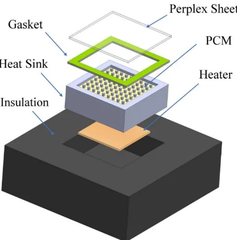
Typical experimental setup used in this research study is shown in Figure 1. Flow diagram in Figure 1, completes the measurement procedure by employing four basics components (DC power supply, PCM filled heat sink assembly, data logger and laptop). A DC power supply (Kaysieght Technologies 6675A, 120V/18A) is used to input the constant heat densities ranging from 1.6𝑘𝑊/𝑚2 to 3.2𝑘𝑊/𝑚2 with a step of 0.4𝑘𝑊/𝑚2. Current and voltage are adjusted using Ohm’s law. DC power supply has accuracy of voltage 0.04% + 120𝑚𝑉 and current 0.1% + 12𝑚𝐴 at reference temperature of 25℃. Four different configurations of finned heat sink are used as a heat storage unit (HSU), which are no fin heat sink chosen as a reference heat sink for baseline comparisons, three round pin-fin heat sinks of 2𝑚𝑚, 3𝑚𝑚 and 4𝑚𝑚 pin diameter having constant volume fractions of 𝛾 = 9% as a thermal conductivity enhancers (TECs). The volume fraction of TCEs denoted by 𝛾 is calculated using Eq.1, which is actually the ratio of volume occupied by the fins to the total empty volume of heat sink.
𝛾 =𝑉𝑇𝐶𝐸
𝑉𝑆 Eq. 1
10
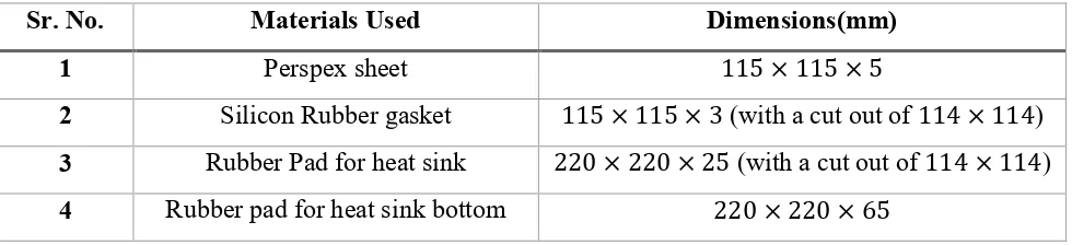
Table 1-Dimensions of material used for HSU.
Sr. No. Materials Used Dimensions(mm)
1 Perspex sheet 115 × 115 × 5
2 Silicon Rubber gasket 115 × 115 × 3 (with a cut out of 114 × 114)
3 Rubber Pad for heat sink 220 × 220 × 25 (with a cut out of 114 × 114)
4 Rubber pad for heat sink bottom 220 × 220 × 65
Each heat sink (acting a HSU) is filled with phase change material (PCM) namely paraffin wax [43]. Experimentation is carried out at three different volumetric fractions of paraffin wax (𝜓 = 0.0, 𝜓 = 0.5 and 𝜓 = 1.0) to investigate the effect of PCM amount for thermal performance of round pin-fin heat sinks. Table 2 provides the material properties used in this research activity. The volumetric fraction of PCM denoted by 𝜓, is calculated using Eq. 2, which is the ratio of PCM volume to the total volumetric capacity of heat sink.
𝜓 = 𝜐𝑃𝐶𝑀
𝑉𝑆−𝑉𝑓 Eq. 2
11
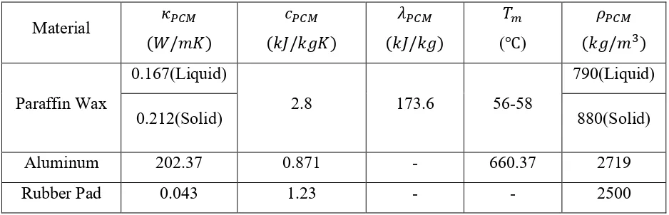
Table 2-Thermo-physical properties of materials.
Material 𝜅𝑃𝐶𝑀 (𝑊/𝑚𝐾) 𝑐𝑃𝐶𝑀 (𝑘𝐽/𝑘𝑔𝐾) 𝜆𝑃𝐶𝑀 (𝑘𝐽/𝑘𝑔) 𝑇𝑚 (℃) 𝜌𝑃𝐶𝑀
(𝑘𝑔/𝑚3)
Paraffin Wax
0.167(Liquid)
2.8 173.6 56-58
790(Liquid)
0.212(Solid) 880(Solid)
Aluminum 202.37 0.871 - 660.37 2719
Rubber Pad 0.043 1.23 - - 2500
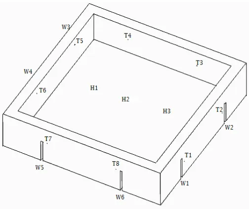
A detail positioning of all thermocouples is shown in Figure 4. The thermocouples denoted by T1-T8 are protruded inside the PCM about 20𝑚𝑚 and fixed at different heights from the heat sink base. Thermocouples T1&T6, T2, T5&T8 and T3, T4&T7 are fixed at 10𝑚𝑚, 15𝑚𝑚 and 20𝑚𝑚 respectively. Whereas W1&W3, W4&W5, and W2&W6 are fixed inside wall of heat sink at 10𝑚𝑚, 15𝑚𝑚 and 20𝑚𝑚, respectively. Thermocouples H1, H2 and H3 are inserted in a 1.5𝑚𝑚 deep groove at equally distanced to measure the heat sink base temperature. All thermocouples are fixed using Araldite ™. A detail of thermocouples inserted inside the paraffin wax and side wall of heat sink is given in Table 3 and 4, respectively.
12
Figure 1-Flow diagram for present experimental HSU.
[image:12.612.176.419.414.660.2]13
Figure 2- Two dimensional projections of 3mm pin diameter heat sink.
[image:13.612.156.408.408.620.2]14
Table 3-Thermocouple positions placed inside the paraffin wax from side walls.
Sr.
No. Type of Heat Sink
Position of thermocouples placed inside the PCM (mm)
T1 T2 T3 T4 T5 T6 T7 T8
1 No Fin 32 32 32 32 32 32 32 32
2 𝜑 = 2𝑚𝑚 41 30 41 30 41 30 41 30
3 𝜑 = 3𝑚𝑚 41 28 41 28 41 28 41 28
4 𝜑 = 4𝑚𝑚 40 30 40 30 40 30 40 30
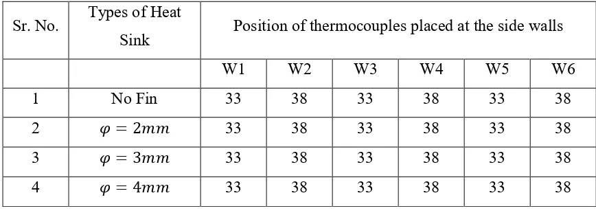
Table 4-Positions of thermocouples located at side walls from side walls.
Sr. No. Types of Heat
Sink Position of thermocouples placed at the side walls
W1 W2 W3 W4 W5 W6
1 No Fin 33 38 33 38 33 38
2 𝜑 = 2𝑚𝑚 33 38 33 38 33 38
3 𝜑 = 3𝑚𝑚 33 38 33 38 33 38
4 𝜑 = 4𝑚𝑚 33 38 33 38 33 38
3-Result and Discussion
3.1-Effect of PCM Volumetric Fractions
[image:14.612.88.522.387.542.2]15
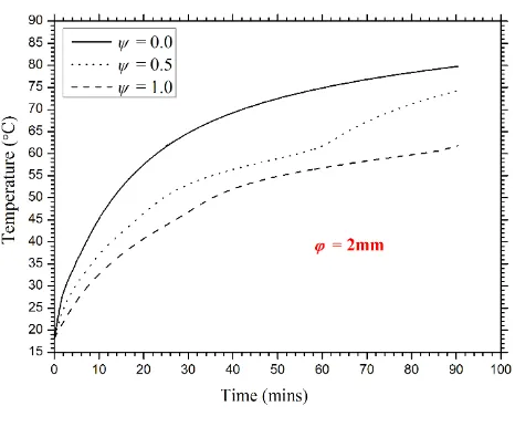
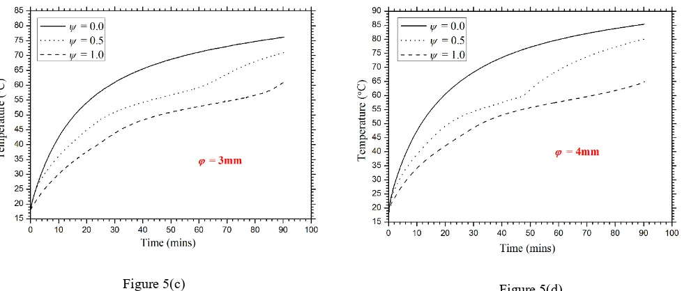
variation for each configuration of heat sinks. It is seen from Figure 5, that a rapid increase in temperature is obtained at 𝜓 = 0.0, which is expected. But at PCM level of 𝜓 = 0.5, the base temperature rises lower than 𝜓 = 0.0, and further a more lower case is seen for an amount of PCM at 𝜓 = 1.0. This ensures that a heat sink either with fins or without fins, a PCM filled at 𝜓 = 1.0 has maximum tendency to keep the heat sink base temperature under reliable and comfort temperature limits.
[image:15.612.332.565.242.435.2]16
Figure 5- Comparison of heat sinks base temperature at different volumetric fractions of PCM (a) No fin
(b) 𝜑 = 2𝑚𝑚 (c) 𝜑 = 3𝑚𝑚(𝑑)𝜑 = 4𝑚𝑚
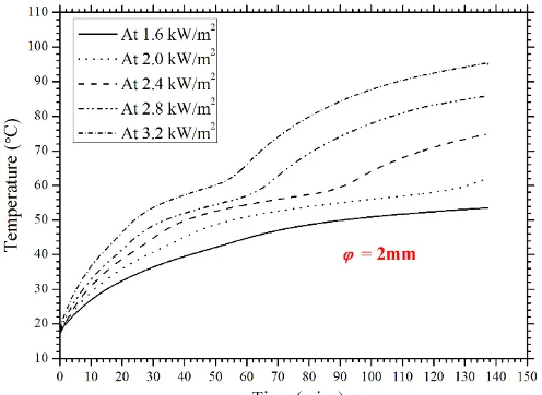
3.2-Effect of Input Heat Flux on Temperature Profile
The effect of different input heat densities is shown in Figure 6 for 2𝑚𝑚 pin diameter heat sink. A range of heat flux from 1.6𝑘𝑊/𝑚2 to 3.2𝑘𝑊/𝑚2 is provided at heat sink base through plate heater. Time-temperature profiles are recorded using base thermocouples H1, H2 and H3 at PCM level of 𝜓 = 1.0. The Figure 6 shows that the latent heating phase gets shorter as the input heat flux increases, as expected. It is seen that no solid-liquid phase change occurs at 1.6𝑘𝑊/𝑚2 even after 140𝑚𝑖𝑛𝑠 but a rapid phase change can be seen for 3.2𝑘𝑊/𝑚2 input heat density, the phase change occurs just after 28𝑚𝑖𝑛𝑠. Further, there is a most significant trend can be seen for latent heating phase completion time.
[image:16.612.74.563.78.287.2]17
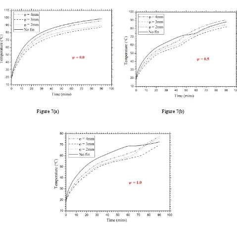
3.3-Effect of Fin diameter of different Heat Sink Configurations
[image:17.612.173.421.81.262.2]Figures 7a-7c reflect the effect of pin diameter of a round pin-fin heat sink in comparison with no fin heat sink. A heat flux of 2.8𝑘𝑊/𝑚2 is provided at the HSU and thermocouples H1, H2 and H3 are used to plot the time-temperature history. Heat sinks of no fin, 2𝑚𝑚, 3𝑚𝑚 and 4𝑚𝑚 pin diameter configurations are filled with three different volumetric fraction (𝜓 = 0.0, 𝜓 = 0.5 and 𝜓 = 1.0) of paraffin wax. It is seen that in all cases of 𝜓, pin diameter of 3mm shows the minimum rise in heat sink base temperature in comparison of no fin, 2𝑚𝑚 and 4𝑚𝑚 pin diameter heat sinks. Latent heating phase duration extends as the amount of PCM doubled as shown in Figures 7b and 7c in cases of finned heat sinks, however an increase in lower base temperature can be evidenced in case of 𝜑 = 3𝑚𝑚 also a slight increase in latent heating phase duration can be seen in case of 𝜑 = 3𝑚𝑚 at 𝜓 = 1.0. A heat sink with lower base temperature and more latent heating phase ensures the best thermal performance to transfer heat in surrounding generated inside compact chips of electronic devices. Furthermore, the variations in temperature profiles of 2𝑚𝑚 and 4𝑚𝑚 pin diameter is either due to the more number of fins or more pitch distance between the fins. Critically, the reason of the best heat transfer characteristics for the case of 3𝑚𝑚 fin diameter heat sink is the optimum number of fins, pitch of fins (the fin spacing in stream-wise, span-wise and diagonal directions). Additionally, the enhanced latent heating phase duration is because of
18
optimum fins distribution which transfer the internal generated heat more uniformly through fins without causing local overheating the heat sink base.
Figure 7(a) Figure 7(b)
Figure 7(c)
[image:18.612.70.549.143.603.2]19
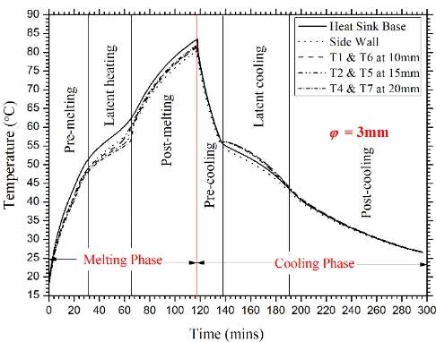
3.4- Temperature variation within PCM for melting and solidification phases.
A complete charging and discharging is shown in Figure 8, for pin diameter of 𝜑 = 3𝑚𝑚 paraffin wax filled heat sink. As it is evidenced from Figure 7c, that a 𝜑 = 3𝑚𝑚 pin-fin heat sink shows the better thermal performance than all compared finned heat sinks. The complete charging and discharging cycle is subdivided into two regions first one is melting phase and second is cooling phase. Both phases are further labeled into three sub-regions shown in Figure 8. Thermocouples fixed at heat sink base, side wall and inside the paraffin wax are chosen to map the transient variations of phase change temperatures for a complete cycle at input power density of 2.8𝑘𝑊/𝑚2.
3.5- Temperature uniformity in spatial directions.
[image:19.612.181.424.286.477.2]The spatial effects of temperature variations inside the paraffin wax at different locations are shown in Figures 9a-9c. Input heat density of 2.8𝑘𝑊/𝑚2 is provided at the base of heat sinks and temperature are recorded at 1500𝑠, 3000𝑠, 4500𝑠 and 6000𝑠 for better graphically represent the melt fraction inside the paraffin wax. Thermocouples at four equally distances are fixed on each heat sink (2𝑚𝑚, 3𝑚𝑚 and 4𝑚𝑚 pin diameter) for better understanding. An average values of thermocouples H1, H2 and H3 inserted at base, T1&T6 located at height 5𝑚𝑚, T2&T5 located at a height of 10𝑚𝑚 and T4&T7 located at a height of 15𝑚𝑚, are taken to map the temperature
20
distribution in vertical direction of a heat sink. As expected, the thermocouples inserted at heat sink base record higher temperature as they are directly in contact with plate heater. However, temperature variations inside the paraffin wax are so significantly abrupt and a uniformity which is due to the natural convection heat transfer can be seen for each configuration of pin-fin heat sink at specific time.
21
3.6-Operation time enhancement of different configurations of heat sinks for critical SPTs
To ensure the thermal performance of different configurations of pin-fin heat sinks tested in this study, enhancement in operation time is presented for three different critical SPTs (i.e. 60℃, 65℃ and 70℃). Bar charts shown in Figure 10a-10b, represent the time taken by the finned heat sinks of various pin diameters to reach the critical SPTs of 60℃ and 70℃. A complete summary of time to reach critical SPTs is given in Table 5 for heat flux range of 2.0𝑘𝑊/𝑚2 to 3.2𝑘𝑊/𝑚2 at 𝜓 = 1.0 volumetic fraction of paraffin wax. Average reading values of thermocouples of H1, H2 and H3 are taken. The critical SPTs chosen are actually the maximum design temperature limit for any portable electronic gadgets at which it can’t lose it functionalities and reliability. It is evident from Figure 10a-10b that a PCM filled pin-fin heat sink of 𝜑 = 3𝑚𝑚 takes maximum time to reach SPTs of either 60℃ or 70℃ in comparison of other PCM filled heat sinks. The time to reach SPT of 60℃ is recorded around 172𝑚𝑖𝑛𝑠 at 2.0𝑘𝑊/𝑚2 and around 61𝑚𝑖𝑛𝑠 at 3.2𝑘𝑊/𝑚2 input heat fluxes for 3𝑚𝑚 pin diameter PCM filled heat sink. Similarly, for SPT of 70℃, for the case of 𝜑 = 3𝑚𝑚, it is noted around 80𝑚𝑖𝑛𝑠 and 130𝑚𝑖𝑛𝑠 at input heat flux of 3.2𝑘𝑊/𝑚2 and of 2.4𝑘𝑊/𝑚2 respectively. This reveals that a 𝜑 = 3𝑚𝑚 round pin-fin PCM filled heat sink has best thermal performance for passive cooling of hand-held electronic devices under reliable and comfort temperature limits. Additionally, a closer look in case of no fin, 𝜑 = 2𝑚𝑚 and 𝜑 = 4𝑚𝑚 depicts
Figure-9(c)
[image:21.612.180.413.85.281.2]22
another picture of coin, the variation in time to reach either 60℃ or 70℃ is due to the local overheating occurring between the layers of paraffin wax which don’t transfer heat to adjacent layer. This results the rapid rise in base temperature instead of keeping lower.
[image:22.612.55.561.288.478.2]As it is evident that 𝜑 = 3𝑚𝑚pin-fin heat sink filled with PCM has the best thermal performance, the Figures 11a-11b show the comparison of enhancement in time for different volume fractions of PCM to reach SPTs of 60℃ and 70℃ respectively. It is seen that, maximum time is achieved in case of 𝜓 = 1.0, as expected either for SPT of 60℃ or 70℃.
Table 5-Time (sec) summary sheet to reach for SPTs at 𝜓 = 1.0.
Type of
Heat Sinks Time for SPT (
𝟔𝟎℃) Time for SPT (𝟔𝟓℃) Time for SPT (𝟕𝟎℃)
𝑞
(𝑘𝑊/𝑚2) 2.0 2.4 2.8 3.2 2.0 2.4 2.8 3.2 2.4 2.8 3.2
No Fin 4345 3355 2155 1710 6285 4630 2910 2305 6845 4575 2930
𝜑 = 2𝑚𝑚 8045 5220 3920 3135 9270 5895 4345 3690 6585 5000 4070
𝜑 = 3𝑚𝑚 10290 5410 4445 3425 13035 6025 4980 4135 7665 5610 4625
23
[image:23.612.55.552.78.268.2]Figure 10(a) Figure 10(b)
Figure 10- Comparison of enhancement time between various configurations of round pin-fin heat sinks (a) SPT=60℃(𝑏)𝑆𝑃𝑇 = 70℃
Figure 11(a) Figure 11(b)
[image:23.612.316.553.79.252.2] [image:23.612.53.557.86.575.2] [image:23.612.85.556.349.563.2]24
3.7-Enhancement ratio with influence of PCM and TCEs
The thermal performance various PCM filled finned heat sinks is carried out by calculating the enhancement ratio for pin-fin heat sink against each input heat density. An enhancement ratio with respect to configuration of TCEs, denoted by 𝜉, is defined as the ratio of at specific volumetric fraction of PCM enhanced finned heat sink to unfinned heat sink. The Eq. 3 is used to calculate the enhancement ratio at PCM of 𝜓 = 1.0 for two selective critical SPTs (60℃ and 70℃).
𝜉 = 𝑡𝑐𝑟𝑤𝑖𝑡ℎ𝑇𝐶𝐸
𝑡𝑐𝑟𝑤𝑖𝑡ℎ𝑜𝑢𝑡𝑇𝐶𝐸 Eq. 3
The Figures 12a-12b show that the pin diameter of 3𝑚𝑚pin-fin heat sink filled with paraffin wax has the higher enhancement ratio at any specific input heat density. A maximum enhancement ratios of 2.4 and 1.6 are obtained is obtain an input density of 2.0𝑘𝑊/𝑚2 and 3.2𝑘𝑊/𝑚2for SPT of 60℃ and for SPT of 70℃ it is 1.6 for an input density of 3.2𝑘𝑊/𝑚2. An enhancement ratio, denote by 𝜀, with the influence of with PCM and without PCM, calculating by using Eq. 4, is shown in Figure 13.
𝜀 = 𝑡𝑐𝑟𝑤𝑖𝑡ℎ𝑃𝐶𝑀
𝑡𝑐𝑟𝑤𝑖𝑡ℎ𝑜𝑢𝑡𝑃𝐶𝑀 Eq. 4
25
3.8-Effect of heat capacity and thermal conductance
To illustrate the thermal performance of round pin-fin heat sinks based on PCM (paraffin wax), specific heat and thermal conductance of each configuration of heat sink is calculated using Eq. 5 and Eq. 6 respectively, given as follows,
Figure 12- Comparison of enhancement ratios between configurations of round pin-fin heat sinks (a) No fin (b) 𝜑 = 2𝑚𝑚
[image:25.612.62.558.107.315.2](c) 𝜑 = 3𝑚𝑚(𝑑)𝜑 = 4𝑚𝑚
Figure 13- Comparison of enhancement ratios between different SPTs for 3mm pin diameter pin-fin heat sink.
[image:25.612.190.419.385.570.2]26 𝑐 = Η
∆𝑇 Eq. 5
𝐺 = Ρ
𝑇𝑚𝑎𝑥−𝑇𝑎𝑚𝑏 Eq. 6
From Figure 14 and 15, it is seen that maximum specific and thermal conductance is achieved in case of 𝜑 = 3𝑚𝑚 pin-fin PCM based heat sink. A heat capacity of is 3.1𝑘𝐽/𝐾 is obtained this shows a higher thermal energy is needed to raise the heat sink temperature. Thermal conductance actually the rate of heat transfer from the surface of PCM influenced heat sink to surrounding and thermal conductance of 5.7 × 10⁻¹𝑊/𝐾 is obtained for 3𝑚𝑚 pin diameter pin-fin PCM based heat sink. An achievement of higher heat capacity and thermal conductance for 𝜑 = 3𝑚𝑚pin-fin
27
Figure 14-Comparsion of heat capacity for different configurations of round pin-fin heat sinks.
[image:27.612.191.425.340.523.2]28
Conclusions
The present experimental study with basic objective is the parametric analysis of HSU containing round pin-fin heat sinks as a TCE filled with PCM (paraffin wax) for efficient TM of portable electronic devices. A constant volume fraction of TCE 𝛾 = 9% was chosen and three different volumetric fractions of paraffin wax were taken for input power densities of 1.6𝑘𝑊/𝑚2 to 3.2𝑘𝑊/𝑚2 with a step of 0.4𝑘𝑊/𝑚2. The results reveal a clear picture that a round pin-fin heat sinks have a tremendous capability for passive TM of electronic equipments. Some contributions from this analysis are as following;
1. It is concluded that a heat sink with volumetric fraction of 𝜓 = 1.0 means fully filled with PCM has more tendency to keep the base temperature in lower comfortable temperature limits than that of 𝜓 = 0.0 or 𝜓 = 0.5.
2. At low input heat densities the PCM filled HSU are so efficient for passive cooling of electronic devices, because it takes more time to phase change occurs.
3. It is concluded that HSU with pin diameter of 3mm pin-fin heat sink filled at 𝜓 = 1.0 is more efficient and has significant thermal performance in comparison of 2𝑚𝑚 and 4𝑚𝑚 pin-fin diameter heat sinks.
4. A uniform temperature distribution is found between TCEs through PCM (paraffin wax) which ensures equally melt fraction of PCM in spatial direction.
5. A maximum enhancement in operation time is evidenced for case of 𝜑 = 3𝑚𝑚 pin-fin
PCM based heat sink either to reach SPTs of 60℃ or 70℃ for each input heat density. 6. It is concluded that more enhancement ratio is obtained for both critical SPTs of 60℃ and
70℃ in case of 3𝑚𝑚 pin diameter pin-fin heat sink in comparison of 2𝑚𝑚 and 4𝑚𝑚 round pin-fin heat sinks.
7. A maximum enhancement ratio of 2.4 is obtained an input heat density of 2.0𝑘𝑊/𝑚2 for SPT of 60℃ on the bases of TCEs and enhancement ratios of 3.2, 3.9 and 4.2 are calculated at input heat densities of 2.4𝑘𝑊/𝑚2, 2.8𝑘𝑊/𝑚2and 3.2𝑘𝑊/𝑚2 respectively for a SPT of 60℃ on the bases of influence of PCM.
8. Finally, analysis of heat capacity and thermal conductance evidence that a round pin-fin
29
30
References
1. Kadam, S.T. and R. Kumar, Twenty first century cooling solution: Microchannel heat sinks. International Journal of Thermal Sciences, 2014. 85: p. 73-92.
2. Kheirabadi, A.C. and D. Groulx, Cooling of server electronics: A design review of existing technology. Applied Thermal Engineering, 2016. 105: p. 622-638.
3. Castell, A. and C. Solé, 11 - Design of latent heat storage systems using phase change materials (PCMs) A2 - Cabeza, Luisa F, in Advances in Thermal Energy Storage Systems. 2015, Woodhead Publishing. p. 285-305.
4. Sahoo, S.K., M.K. Das, and P. Rath, Application of TCE-PCM based heat sinks for cooling of electronic components: A review. Renewable and Sustainable Energy Reviews, 2016.
59: p. 550-582.
5. Nkwetta, D.N. and F. Haghighat, Thermal energy storage with phase change material—A state-of-the art review. Sustainable Cities and Society, 2014. 10: p. 87-100.
6. Casini, M., 5 - Phase-change materials, in Smart Buildings. 2016, Woodhead Publishing. p. 179-218.
7. Wang, X.-Q., C. Yap, and A.S. Mujumdar, A parametric study of phase change material (PCM)-based heat sinks. International Journal of Thermal Sciences, 2008. 47(8): p. 1055-1068.
8. Qu, Z.G., et al., Passive thermal management using metal foam saturated with phase change material in a heat sink. International Communications in Heat and Mass Transfer, 2012. 39(10): p. 1546-1549.
9. Mahrous, A., THERMAL PERFORMANCE OF PCM-BASED HEAT SINKS. International Journal of Mechanical Engineering. 2(4).
10. Grujicic, M., C.L. Zhao, and E.C. Dusel, The effect of thermal contact resistance on heat management in the electronic packaging. Applied Surface Science, 2005. 246(1–3): p. 290-302.
31
12. Reza Hajmohammadi, M., et al., Improvement of Forced Convection Cooling Due to the Attachment of Heat Sources to a Conducting Thick Plate. Journal of Heat Transfer, 2013.
135(12): p. 124504-124504-4.
13. Hajmohammadi, M.R., Reply to: Comments on “Detailed analysis for the cooling performance enhancement of a heat source under a thick plate” by Hajmohammadi et al.
Energy Conversion and Management, 2016. 129(Supplement C): p. 52-53.
14. Hajmohammadi, M., et al., Constructal placement of unequal heat sources on a plate cooled by laminar forced convection. International Journal of Thermal Sciences, 2012. 60: p. 13-22.
15. Hajmohammadi, M., et al., Heat transfer improvement due to the imposition of non-uniform wall heating for in-tube laminar forced convection. Applied Thermal Engineering, 2013. 61(2): p. 268-277.
16. Najafi, H., B. Najafi, and P. Hoseinpoori, Energy and cost optimization of a plate and fin heat exchanger using genetic algorithm. Applied Thermal Engineering, 2011. 31(10): p. 1839-1847.
17. Baby, R. and C. Balaji, Experimental investigations on phase change material based finned heat sinks for electronic equipment cooling. International Journal of Heat and Mass Transfer, 2012. 55(5-6): p. 1642-1649.
18. Baby, R. and C. Balaji, Thermal optimization of PCM based pin fin heat sinks: An experimental study. Applied Thermal Engineering, 2013. 54(1): p. 65-77.
19. Jaworski, M., Thermal performance of heat spreader for electronics cooling with incorporated phase change material. Applied Thermal Engineering, 2012. 35: p. 212-219. 20. Tigner, J., et al., Analysis of a platform for thermal management studies of microelectronics
cooling methods. Applied Thermal Engineering, 2013. 60(1–2): p. 88-95.
21. Baby, R. and C. Balaji, Thermal performance of a PCM heat sink under different heat loads: An experimental study. International Journal of Thermal Sciences, 2014. 79: p. 240-249.
32
23. Alshaer, W.G., et al., Numerical investigations of using carbon foam/PCM/Nano carbon tubes composites in thermal management of electronic equipment. Energy Conversion and Management, 2015. 89: p. 873-884.
24. Alshaer, W.G., et al., Thermal management of electronic devices using carbon foam and PCM/nano-composite. International Journal of Thermal Sciences, 2015. 89: p. 79-86. 25. Fan, L.-W., et al., Transient performance of a PCM-based heat sink with high aspect-ratio
carbon nanofillers. Applied Thermal Engineering, 2015. 75: p. 532-540.
26. Kalbasi, R. and M.R. Salimpour, Constructal design of phase change material enclosures used for cooling electronic devices. Applied Thermal Engineering, 2015. 84: p. 339-349. 27. Nada, S.A. and W.G. Alshaer, Comprehensive parametric study of using carbon foam
structures saturated with PCMs in thermal management of electronic systems. Energy Conversion and Management, 2015. 105: p. 93-102.
28. Srikanth, R., P. Nemani, and C. Balaji, Multi-objective geometric optimization of a PCM based matrix type composite heat sink. Applied Energy, 2015. 156: p. 703-714.
29. Ahmed, T., et al. Experimental Investigation of Thermal Management of Tablet Computers using Phase Change Materials (PCMs). in Proc. of the ASME 2016 Summer Heat Transfer Conference. 2016.
30. Fan, L.-W., et al., Transient performance of a thermal energy storage-based heat sink using a liquid metal as the phase change material. Applied Thermal Engineering, 2016. 109, Part A: p. 746-750.
31. Sahoo, S.K., P. Rath, and M.K. Das, Numerical study of phase change material based orthotropic heat sink for thermal management of electronics components. International Journal of Heat and Mass Transfer, 2016. 103: p. 855-867.
32. Swaminathan Gopalan, K. and V. Eswaran, Numerical investigation of thermal performance of PCM based heat sink using structured porous media as thermal conductivity enhancers. International Journal of Thermal Sciences, 2016. 104: p. 266-280. 33. Thomas, J., et al., Thermal Performance Evaluation of a Phase Change Material Based
Heat Sink: A Numerical Study. Procedia Technology, 2016. 25: p. 1182-1190.
33
35. Wang, H., et al., Experimental investigation on the thermal performance of a heat sink filled with porous metal fiber sintered felt/paraffin composite phase change material.
Applied Energy, 2016. 176: p. 221-232.
36. Alimohammadi, M., et al., Experimental investigation of the effects of using nano/phase change materials (NPCM) as coolant of electronic chipsets, under free and forced convection. Applied Thermal Engineering, 2017. 111: p. 271-279.
37. Gharbi, S., S. Harmand, and S.B. Jabrallah, Experimental study of the cooling performance of phase change material with discrete heat sources – Continuous and intermittent regimes.
Applied Thermal Engineering, 2017. 111: p. 103-111.
38. Srikanth, R. and C. Balaji, Experimental investigation on the heat transfer performance of a PCM based pin fin heat sink with discrete heating. International Journal of Thermal Sciences, 2017. 111: p. 188-203.
39. Arshad, A., et al., Thermal performance of phase change material (PCM) based pin-finned heat sinks for electronics devices: Effect of pin thickness and PCM volume fraction.
Applied Thermal Engineering, 2017. 112: p. 143-155.
40. Ali, H.M. and A. Arshad, Experimental investigation of n-eicosane based circular pin-fin heat sinks for passive cooling of electronic devices. International Journal of Heat and Mass Transfer, 2017. 112: p. 649-661.
41. Ashraf, M.J., et al., Experimental passive electronics cooling: Parametric investigation of pin-fin geometries and efficient phase change materials. International Journal of Heat and Mass Transfer, 2017. 115, Part B: p. 251-263.
42. Put, S., et al., Die sink electrodischarge machining of zirconia based composites. British ceramic transactions, 2001. 100(5): p. 207-213.
43. EMD Millipore is a part of Merck KGaA, D., Germany. 2016; Available from: http://www.emdmillipore.com/US/en/product/Histosec-pastilles,MDA_CHEM-111609. 44. Taylor, B.N. and C.E. Kuyatt, Guidelines for evaluating and expressing the uncertainty of