The Series Bridge Converter (SBC): Design of a
Compact Modular Multilevel Converter for Grid
Applications
Emmanuel Amankwah
†, Alessandro Costabeber
†, Alan Watson
†, David Trainer
*, Omar
Jasim
*, Javier Chivite-Zabalza
*and Jon Clare
††The University of Nottingham,
Power Electronics, Machines and Control Group, University Park, Nottingham
NG7 2RD, UK
*GE Energy Connections
St Leonard’s Avenue, Stafford, ST17 4LX, UK
Abstract—This paper presents a novel hybrid modular multilevel voltage source converter suitable for grid applications. The proposed converter retains the advantages of other modular multilevel topologies and can be made more compact making it attractive for offshore stations and other footprint critical applications like city infeeds. In this paper, the basic operating principle and design criteria for the converter implementation are presented. The submodule capacitor requirements which have significant influence on the size of a converter station are also evaluated and compared to the MMC.
The performance of the converter is supported by simulation results from a representative medium voltage scaled demonstrator.
Index Terms—MMC, Converter design, capacitor sizing, Offshore, Compact HVDC VSC systems
I. INTRODUCTION
here is currently significant interest in harnessing the vast amount of renewable wind energy available offshore[1]. However, one of the main impediments to offshore wind exploitation is the energy transmission to the load centres which are often located hundreds of kilometres away from the wind farms. In these cases, HVDC is the preferred medium of power transmission from the offshore and remote locations due to its advantages for long distance and underwater transmission [2]. Until quite recently when VSC HVDC systems have become popular due to the introduction of multilevel VSCs, LCC HVDC systems were the standard solution for HVDC projects due to their high efficiency. The voltage and current waveform quality from modular multilevel VSC HVDC systems are better than LCC, and the stress across the devices is reduced. Also the HVDC station footprint is reduced due to reduced AC filtering, but efficiency is normally lower due to the higher semiconductor loss. When considering footprint critical applications like offshore platforms and city centre infeeds, size and loss of the VSC play a significant role in the station cost and hence return on investment time.
Modular Multilevel Voltage Source Converters (MMC) are being developed for VSC HVDC applications [3-6]. The modular approach makes the converters scalable and adaptable to a wide range of high voltage and high power
applications. A number of MM-VSCs are currently in operation and many more are planned [7-9]. Among them, the Modular Multilevel Converter (MMC) [6] has been the focus of many research and industrial projects [10] for its well-known advantages in terms of high power quality, low losses, and ability to inject power into weak network.
In the last decade a number of MM-VSC topologies suitable for HVDC [3, 5, 6, 11] have been proposed in the literature and extensively investigated. Among them the Alternate Arm Converter (AAC) [4] which involves the combination of the MMC concept [6] with the 2-level converter concept [12]. If the MMC and the AAC are based on a parallel connection of phases on the DC side, another family of converters can be developed based on a series connection configuration on the DC side [3, 13].
The SBC topology [14] is based on the concept originally presented in [3]. The converter arrangement uses the series connection on the DC side of three single phase converters, each of them made up of a combination of shunt connected half bridge submodules and series connected full bridge submodules. Each phase synthesises a full wave rectified sinusoid which is ‘unfolded’ by a line frequency soft-switched H-bridge converter to generate the AC voltage. With the proposed circuit, the number of submodules required is typically 30 - 35% of that required by an equivalent MMC. This paper presents an overview of the converter topology and its operating principles, together with design criteria for implementation in an HVDC system. The submodule capacitor sizing requirements are investigated. It is shown that the converter can be made very compact making it attractive for VSC HVDC applications. The concepts discussed in the paper are validated using a simulation model from a representative medium voltage model.
II. CONVERTERTOPOLOGY
Figure 1 shows the basic structure of the SBC. Each phase is composed of two converter arms and an H-bridge. The shunt connected arm with half-bridge submodules is named Chain-Link (CL), while the series connected arm with Series Full Bridges is called SFB arm. The CL and SFB arms are responsible for synthesising a variable amplitude full wave rectified sinusoidal voltage at the DC input of the main
bridge. The main H-bridges “unfold” the waveform at the zero crossings to generate the AC voltages across the primary side of three open winding transformers as shown in Figure 1. The three series connected CL units support the DC bus voltage while the three SFB units operate to decouple the AC network from the DC network and achieve full control of the AC side voltage and current. The resulting converter can be made more compact by optimising the submodules in the shunt connected rail (consisting of half bridge submodules) across the DC bus and that in the series branch which appears in the main power path. Also, the unfolding process operated by the main H-bridge guarantees that the AC voltages and currents seen by the submodules are of high frequency and therefore the voltage ripple across the submodule capacitors are of high frequency. Another advantage is that only a fraction of the composite DC current flows through the CL arms, leading to less conduction loss. Though the H-bridge based SFB arms are placed in the full current path, the number of submodules in the two arms is optimally selected to achieve the required PQ operation. This reduces significantly the semiconductor loss and the size of the converter.
III. OPERATINGPRINCIPLE
To introduce the basic operating principle of the SBC, consider a balanced and stiff three phase AC network, with the impedances dominated by the leakage inductances of the transformers, and consider first converter operation at unity power factor.
In this case, ideally, the SFB arms can be considered to be under minimum utilisation. To understand the role of SFBs, assume first that they are all bypassed and the operation of the converter is as discussed in [3]. In this condition, the three CLs generate three full wave rectified sinusoids displaced 120 electrical degrees resulting in VCLx = VINx. These will be “unfolded” at the zero-crossings by the main H-bridges, and active power can be exchanged by controlling the phase
shift with respect to the grid voltage. Consider a generic phase shift δ between the grid voltage and the converter voltage, and a corresponding phase shift φ of the grid current. In Figure 1, considering for instance phase ‘a’ the voltages and currents can be described as (1):
INa CLa
SFBa
Ca INa a
C Ca
G Ga
V t V t
V
t V V t
I t I
t V
t V t
V t V
) ( , 0 ) (
, ) ( )
sin( )
(
), sin( )
( ),
sin( )
(
(1)
As discussed in [3], in a three phase system, the average voltage demand on the DC sideVDCC corresponds to the sum
of the three average values of the CL voltages VCLx. In the
presentation in [3] the effects of the SFB arms are not considered, which makes the amplitude of the converter voltages directly related to the DC voltage and influences the selection of the turns ratio of the transformer.
To decouple the peak converter voltage, VC from the composite DC voltage (VDCC) in the CLs, the SFB arms would be required to synthesise the residual voltage between the voltage at the converter terminal, VCx(t) and that synthesised by the corresponding CL arm (VCLx). As we shall see later, with the formulation in [3], Fourier spectrum of the individual CL voltages contains even harmonics 2n, which cancel out in the sum across the three phases except for the 6n. For this reason, in the new formulation as considered in this paper, the SFBs are used not only to facilitate reactive power control but also to improve power quality on the DC side by extracting the 6n characteristic harmonic voltages from the DC circuit.
[image:2.595.82.506.519.738.2]Consider now a more general case where the SFBs are inserted into the circuit. With a fixed DC bus voltage, VDCC, the amplitude of the rectified sinusoids forming the CL voltages can be derived for a given DC network voltage. For optimal use of the converter arms the voltage formulation from the CLs are synchronised to the grid voltages (2).
Figure 1: The Series Bridge Converter (SBC) Topology S3
S2 S1
S4
VCLa
Converter phase B
Converter phase C 1:r
VINa
R L
IDC
VCa VCc
VCb
VDCC VGa
VGb
VGc
Ix
VDC LDC
VSFBa ISFBa
2 /3
sin )
(
6
y t V t V V
VCL DCC CLx CL (2)
The Fourier series of VCLxin (2) is derived as (3).
0,1,2
3 / 2 cos 1 1 2 1 2 ) ( 6 , 4 , 2 2
y yn t n n V t V n CLCLx (3)
Summation of the three CL voltages in (3) results in (4)
6,12,18.. 2
) cos( 1 1 2 1 6 ) ( n CL
DCC n t
n V
t
V
(4)
It is clear from (4) that the total voltage across the CLs is composed of a DC and 6n harmonic voltages and therefore the characteristic 6n harmonics can be extracted to improve the power quality on the DC network without affecting the converter operation.
Considering (1) and (2), and ignoring the DC power quality improvements for now, the SFBs are required to generate the difference between VCLxand VINxto facilitate voltage wave shaping (5).
sin 2 /3
) ( 3 / 2 sin
y t V V t V y t V V CL C SFBx C INx (5)The 6n characteristic harmonics in each CL can be obtained from (3) as (6).
) cos( 1 1 4 ) ( .. 18 , 12 , 6 2 t n n V t V n CL
R
(6)
Subtraction of the characteristic harmonics in (6) from the CL voltage formulation in (2) and adding it to the SFB arm voltage formulation clearly removes all the harmonics from the DC circuit while maintaining the AC voltage quality. In summary, the CL voltage, the SFB voltage and the input voltage for the main H-bridge that guarantees full power control and active DC filtering are presented in (7).
t unfolding V t V
t V t V t V t V t n n V t V V t V t V V t V t n n V t V t V t V t V C Ca C SFBa CLa INa n CL CL C R CL C SFBa n CL CL R CL CLa sin ) ( sin ) ( ) ( ) ( cos 1 1 4 sin ) ( sin ) ( cos 1 1 4 sin ) ( sin ) ( 18 , 12 , 6 2 18 , 12 , 6 2
(7)So far the concept of voltage wave shaping in the SBC has been illustrated, considering the converter arms as ideal voltage sources. However, for sustainable operation the net energy into the converter and any sub-units has to be zero during normal operation. It can be shown that using the above method of voltage formulation, the net power into the converter arms can be described by (8).
ACa SFBaC CL DC C U DC DCC
CLa P P
V V P I V K I V
P
3 cos
2
3 (8)
Clearly, the net power into the CLs and the SFBs are equal and opposite but not zero whenever the SFBs are involved in
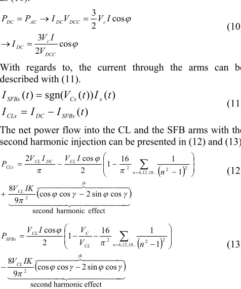
voltage synthesis (i.e VCL≠ Vc). It is proposed to control the power flow into the converter arms by adding a second harmonic voltage in CLs and SFBs in each phase. The addition of the second harmonic voltages with the same amplitude but in phase opposition in SFBs and CLs enables the control of the individual powers to zero. The second harmonic voltage for inter-arm energy management does not appear in the AC or DC network and therefore does not affect the voltage or power quality in the HVDC system. The second harmonic injection concept explored in this paper is in all aspects different from that which has been explored for local capacitor voltage ripple minimisation in other MMC applications [15]. Now consider a system where the converter CL and SFB voltages are redefined with a proportion of second harmonic voltage as (9).
3 / 4 2 cos 3 4 ) ( ) ( 3 / 2 sin ) ( ) ( 3 / 2 sin ) ( y t KV t V t V t V y t V V t V t V t V y t V t V CL EMx EMx R CL C SFBx EMx R CL CLx (9)Considering that AC-DC power balance is required for sustainable operation of the converter and imposing the said constraint, the current flow in the DC circuit can be obtained as (10). cos 2 3 cos 2 3 DCC c DC c DCC DC AC DC V I V I I V V I P P (10)
With regards to, the current through the arms can be described with (11).
) ( ) ( )) ( sgn( ) ( t I I I t I t V t I SFBx DC CLx x Cx SFBx (11)
The net power flow into the CL and the SFB arms with the second harmonic injection can be presented in (12) and (13).
effect harmonic second cos sin 2 cos cos 9 8 1 1 16 1 2 cos 2 2 .. 18 , 12 ,6 2 2
2 k CL n CL DC CL CLx IK V n I V I V P
(12)
effect harmonic second cos sin 2 cos cos 9 8 1 1 16 1 2 cos 2 .. 18 , 12 ,6 2 2
2 k CL n CL C CL SFBx IK V n V V I V P
(13)If the factor k of the second harmonic effect is set to be constant and in this case unity as will be discussed later, then K (14) can be selected to ensure zero net power into the converter CL and SFB arms throughout the operating points.
CL C n V V n K ,.. 18 , 12 ,6 2 2
[image:3.595.307.545.337.622.2]2 2 1 1 16 1 cos 16 9 (14)
Table 1: Parameters of the Demonstrator
System Parameter Values
AC System Voltage , VLL 11kV DC System Voltage , VDC 20kV
Rated Active Power, P 20MW
Figure 2: K: - proportion of second harmonic voltage injected for inter-arm energy management
Figure 3: Maximum CL voltage for varying operating points
Figure 4: Maximum and minimum SFB voltages for varying operating points
Clearly, with the substitution of K and considering IDCfrom the power balance equation (10), the net power into the converter CL and SFB can be made zero. Figure 2 shows the variation of the proportion of second harmonic voltage in a
CL that is required for energy management between the two arms in a phase for the system described in Table 1.
[image:4.595.57.293.232.359.2]With the voltage formulation where ripple cancellation of the characteristic 6n harmonics and inter-arm energy management is achieved, the maximum voltage in the CL for the target application envelope is shown in Figure 3 and the Maximum and minimum voltages in the SFB are shown in Figure 4.
IV. NUMBER OFDEVICES
As presented in Figure 3, the maximum voltage to be synthesised by a converter CL arm is about 11.5kV and about 3.05kV (Figure 4) for SFB arms for the medium voltage demonstrator considered in this paper. Assuming that the intra arm cell voltage management algorithm evenly distributes the voltage pulsation equally among the submodules as implemented in this project, the ripple due to the submodule capacitor voltage will be minimal. Therefore, considering a 1.5kV rated submodules, 8 submodules per CL and 3submodules per SFB arm are selected for the demonstrator implementation.
V. SUBMODULECAPACITORSIZING
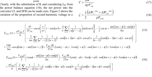
Given that the converter arms generate a full wave rectified sinusoids as described in Section III, the instantaneous energy in the CL and SFB arms can be described with (15) and (16) respectively, ignoring the effect of the DC reactor, LDC. Evaluation of the given expressions in (15) and (16) for a representative 20kV, 20MW system with 12% leakage inductance shows that the peak–peak energy pulsation in the CL arms is 13.41kJ and that in the SFB arms is 4.383kJ. From these results, the required capacitance can be derived for a given % peak-peak ripple ( ) of the capacitor voltage using (17). Where C is the capacitance of the submodule, n is the number of submodules in the arm, Vcap is the nominal submodules voltage and Wmaxis the max peak-peak energy of an arm.
2 max
cap
V n
W C
(17)
rated sfb cl
P W W
max max
2
3
(18)
t t
IK V t
VIK
t n n
t n n
n
t t
t n n
n t
V V I V t E
DC DC
DC CLx
cos 3 3
cos cos
3 ) cos( 27
2 sin sin cos 6
cos 1
cos 1 1 cos
1 cos 1 1 1 1 2
4 sin 2
sin cos 2 sin
1 1 4
cos 1 1 cos 2
3
6 ) (
12 , 6 2
12 ,
6 2 (15)
12 , 6 2cos 1
cos 1 1 cos 1
cos 1 1 1 1 2 6
cos 3 3
cos cos
3 ) cos( 27 2
sin 2
sin cos 2 ) (
t n n
t n n
n I
V
t t
IK V t
t I V t E
DC
DC SFB
[image:4.595.48.550.515.771.2]From the maximum peak-peak energy results obtained from the evaluation of (15) and (16), and the number of submodules required for each arm to fulfil the voltage synthesise, the capacitance requirement for the converter submodules (17) can be presented as Figure 7 for varying ripple factors. Clearly, the time constant (ζ) of the SBC configuration under study can be presented as (18) similar to that of the MMC discussed in [4, 16]. In such analysis, the time constant of the SBC is 13.34kJ/MW with a 10% ripple factor which is 33.4- 44% of that required for a standard MMC. For uniformity in the submodule design, 4mF capacitors are selected for use in the CL and SFB arms which corresponds to 18.6% and 16.2% ripple factors at the extreme operating points of rated Q (capacitive for the CLs and inductive for the SFBs).
VI. SIMULATIONRESULTS
Considering the voltage range requirement of the CL and the SFB arms as discussed in Sections IV and V, 8 half bridge submodules and 3 full bridge modules rated at a nominal voltage of 1.5kV with a local capacitor of 4mF each are used to populate the converter arms. With regards to the smaller number of submodules used in the demonstrator compared to that which would be required in a practical system, PWM methods are used to modulate the submodules to increase the voltage fidelity and waveform quality. The converter is operated to exchange active and reactive power with the grid as would be expected of a VSC- HVDC converter. In line with the results presented in Figure 5 and 6, further results from an actual switching model are presented to support the operation of the converter for unity PF operation. However, sustainable operation of the converter has been successfully validated throughout the designed PQ envelope.
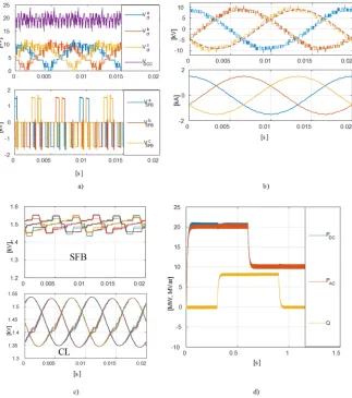
The voltages synthesised by the CL arms, the total across the three CL arms and that synthesised by the SFB arms are
[image:5.595.322.538.246.375.2]presented in Figure 8a. It can be observed that the total CL voltage, VDCC, is clean of the low order harmonics other than high frequency switching effects. As mention earlier, the voltage demand on the SFB arm is very small compared to that required by the CL arms. It can be observed from Figure 8b, that the voltage synthesised by the converter and the current exchanged between the converter and the grid are of high quality. Internal energy management control is confirmed with the successful control of the CL and SFB submodule capacitor voltages around the nominal value of 1.5kV in Figure 8c. In Figure 8d, transient performance of the converter is demonstrated with power traversal from rated power (Unity PF) to rated power and full reactive power capacitive, and finally to half rated power. In all this power traversal, internal energy management of the converter is maintained.
Figure 7: Variation of submodule capacitance with ripple factor
VII. CONCLUSIONS
[image:5.595.77.516.497.645.2]In this paper, the operation and design of a compact modular multilevel converter which is suitable for offshore VSC-HVDC application and city infeeds has been presented. Simulation results from the designed medium voltage demonstrator have been presented to support operation of the considered converter circuit.
Figure 5: Waveforms at P=20MW, Q=0MVAr with DC ripple cancellation and energy management - (a) Grid voltages VGx(thin lines) and converter
voltages VCx(thick lines) (b) Grid currents (c) Main H-bridge voltages VInx(d) Folded currents ISFBx(e) CL voltages (f) SFB voltages
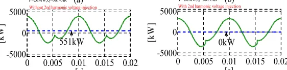
Figure 6: CL instantaneous (dashed) and average powers (a) P=20MW,Q=0MVAr without 2ndharmonic injection, (b) with 2ndharmonic injection
0 0.005 0.01 0.015 0.02 -10
0
10 (a)
[k
V
]
0 0.005 0.01 0.015 0.02 -2
0
2 (b)
[s]
[k
A
]
a b c
a b c
0 0.005 0.01 0.015 0.02 0
5
10 (c)
[k
V
] a
b c
0 0.005 0.01 0.015 0.02 -0.5
0 0.5 1
1.5 (d)
[s]
[k
A
] ab
c
0 0.005 0.01 0.015 0.02 0
10 20
(e)
[k
V
] ab
c DC
0 0.005 0.01 0.015 0.02 -2
0
2 (f)
[k
V
]
[s]
a b c
0 0.005 0.01 0.015 0.02
-5000 0 5000
(a)
[k
W
]
551kW Without 2nd harmonic voltage injection
P=20MW,Q=0MVAR
0 0.005 0.01 0.015 0.02 -5000
0 5000
(b)
[k
W
]
[s] 0kW
With 2nd harmonic voltage injection
P=20MW,Q=0MVAR
0 0.005 0.01 0.015 0.02
[image:5.595.156.437.679.748.2]Figure 8: Waveforms demonstrating the operation of the converter at rated power (P=20MW) and Unity PF a) Chain-Link (upper) and SFB (lower) voltages, b) Converter and Grid phase voltages and line currents c) SFB and Chain-Link capacitor voltages and PQ transient response d)
VIII. REFERENCES
[1] N. M. MacLeod, C. D. Barker, and N. M. Kirby, "Connection of renewable energy sources through grid constraint points using HVDC power transmission systems," inIEEE PES T&D 2010, 2010, pp. 1-7.
[2] J. A. Y. H. L. N. R. Watson;,Flexible Power Transmission: The HVDC Options: John Wiley & Sons, Ltd 2007
[3] R. Feldman, M. Tomasini, E. Amankwah, J. C. Clare, P. W. Wheeler, D. R. Trainer, et al., "A Hybrid Modular Multilevel Voltage Source Converter for HVDC Power Transmission,"
Industry Applications, IEEE Transactions on,vol. 49, pp. 1577-1588, 2013.
[4] M. M. C. Merlin and T. C. Green, "Cell capacitor sizing in multilevel converters: cases of the modular multilevel converter and alternate arm converter,"Power Electronics, IET,vol. 8, pp. 350-360, 2015.
[5] G. P. Adam, Finney, S. J., Williams, B. W.,Trainer, D. R.,Oates, C. D. M.,Critchley, D. R., "Network fault tolerant voltage-source-converters for high-voltage applications," inAC and DC Power Transmission, 2010. ACDC. 9th IET International Conference on, 2010, pp. 1-5.
[6] A. Lesnicar and R. Marquardt, "An innovative modular multilevel converter topology suitable for a wide power range," inPower Tech Conference Proceedings, 2003 IEEE Bologna, 2003, p. 6 pp. Vol.3.
[7] H. J. Knaak, "Modular multilevel converters and HVDC/FACTS: A success story," in Power Electronics and Applications (EPE 2011), Proceedings of the 2011-14th European Conference on, 2011, pp. 1-6.
[8] L. B. Feng Wang, Tuan Le, "An Overview of VSC-HVDC : State - of - art and potential applications in Electric Power Systems,"
Cigre,2011.
[9] J D Ainsworth, M Davies, P J Fitz, K E Owen, and D. R. Trainer, "A static var compensator (STATCOM) based on single phase chain circuit convertors," IEE Proceedings, Generation, Transmission and Distribution,vol. 145, July 1998.
[10] K. Friedrich, "Modern HVDC PLUS application of VSC in Modular Multilevel Converter topology," in 2010 IEEE International Symposium on Industrial Electronics, 2010, pp. 3807-3810.
[11] D. R. Trainer, Davidson, C. C., Oates, C. D. M., Macleod, N. M., & Critchley, D. R. , "A New Hybrid Voltage-Sourced Converter for HVDC Power Transmission," inCigre2010.
[12] G. Asplund, "Application of HVDC Light to power system enhancement," inPower Engineering Society Winter Meeting, 2000. IEEE, 2000, pp. 2498-2503 vol.4.
[13] E. K. Amankwah, J. C. Clare, P. W. Wheeler, and A. J. Watson, "Cell capacitor voltage control in a parallel hybrid modular multilevel voltage source converter for HVDC applications," in
Power Electronics, Machines and Drives (PEMD 2012), 6th IET International Conference on, 2012, pp. 1-6.
[14] O. F. Jasim and D. R. Trainer, "Voltage Source Converter," EP2858231A1, 2015.
[15] R. Picas, J. Pou, S. Ceballos, J. Zaragoza, G. Konstantinou, and V. G. Agelidis, "Optimal injection of harmonics in circulating currents of modular multilevel converters for capacitor voltage ripple minimization," inECCE Asia Downunder (ECCE Asia), 2013 IEEE, 2013, pp. 318-324.