Contents lists available atScienceDirect
Composites Part B
journal homepage:www.elsevier.com/locate/compositesb
Shear strengthening of concrete members with TRM jackets: E
ff
ect of shear
span-to-depth ratio, material and amount of external reinforcement
Zoi C. Tetta
a,∗, Lampros N. Koutas
b, Dionysios A. Bournas
caDeprt. of Civil Engineering, University of Nottingham, NG7 2RD, Nottingham, UK bDept. of Civil Engineering, University of Thessaly Volos, GR-38221 Greece
cEuropean Commission, Joint Research Centre (JRC), Directorate for Space, Security & Migration, Safety and Security of Buildings Unit, Via E. Fermi 2749, I-21027, Ispra, Italy
A R T I C L E I N F O
Keywords:
Carbonfibre Glassfibres Debonding Fracture Basaltfibres
A B S T R A C T
An experimental work on reinforced concrete (RC) rectangular beams strengthened in shear with textile re-inforced mortar (TRM) jackets is presented in this paper, with focus on the following investigated parameters: (a) the amount of external TRM reinforcement ratio,ρf, by means of using different number of textile layers and different types of textilefibre materials (carbon, glass, basalt); (b) the textile geometry, and (c) the shear span-to-depth ratio,a/d. In total, 22 tests were conducted on simply supported rectangular RC beams under (three-point bending) monotonic loading. The experimental results revealed that: (1) TRM is very effective when the failure is attributed to debonding of the TRM jacket from the concrete substrate; (2) the trend of effective strains for carbon, glass and basalt TRM jackets is descending for increasing values of the TRM reinforcement ratio,ρf, when failure is associated to debonding of the jacket; (3) the effect of textile geometry is significant only for low values ofρf, resulting in variances in the capacity enhancement and the failure modes, and (4) the shear span-to-depth ratio has practically no effect to the failure mode nor to the TRM jacket contribution to the total shear resistance of the RC beams.
1. Introduction and background
Over the last decades, there is an increasing need to upgrade many of the existing RC structures both in seismic and non-seismic areas mainly due to their ageing, lack of maintenance, deterioration, and environmental induced degradation.
A composite material called textile-reinforced mortar (TRM) has been introduced since last decade, for structural strengthening of ex-isting structures[1,2]. TRM consists of textilefibre reinforcement (with open-mesh configuration) combined with inorganic matrices (i.e. ce-mentitious mortars). The acronym‘FRCM’is also used in the literature for the same material [3]. TRM is a low-cost, resistant at high tem-perature [4–6], compatible to masonry or concrete substrates and friendly for manual workers material, which can be applied at low temperatures or on wet surfaces. Therefore, the use of TRM is becoming more attractive for the retrofitting of existing concrete or masonry structures than fiber-reinforced polymers (FRP) which have been widely used but haves some drawbacks (i.e. high prices, inapplicability at low temperatures or wet surfaces, combustibility that could boostfire spreading and generally very poor performance at high temperature) due to the epoxy resins used in these composites. Bond between TRM or
FRCM and concrete substrates has been widely studied in the last decade [i.e.5, 7–8]. TRM has also been studied forflexural strength-ening [i.e.9–14], torsional strengthening [15], confinement, seismic retrofitting of RC elements [16–19], repairing of corroded T-beams [20], strengthening of masonry elements[21–26]has been found to be a very promising solution. Examples of real applications of TRM system are presented in Ref.[27]. A variety of studies on TRM have been published the last year (2017), indicating that TRM is on the spotlight of recent research[28–41].
The assessment of existing RC structures with the existing standards (i.e. Eurocodes) often results in shear deficient beams or bridge girders due to corrosion of the shear links, low concrete strength or/and in-creased applied loads. A number of studies have investigated the use of TRM jacketing for shear strengthening of RC beams[1,42–53]. In these studies the main investigated parameters were the performance of TRM versus FRP jackets [1,46,48,52,53], the number of layers [1,42,44,46,48,51,52], the strengthening configuration [45,48], the anchorage of TRM U-shaped jackets in T-beams[22,44,52] and the amount of internal shear reinforcement[53].
In particular, Tzoura and Triantafillou [46] reported that FRP jackets (that failed due to debonding of the jacket) were much more
∗Corresponding author.
E-mail addresses:[email protected](Z.C. Tetta),[email protected](L.N. Koutas),[email protected](D.A. Bournas).
effective than their counterparts TRM jackets which failed due to slip-page offibres through the mortar. In contrast, Tetta et al.[48], Tetta et al.[52]and Awani et al.[53]concluded that TRM U-shaped jackets are practically as effective as equivalent FRP U-shaped jackets due to the common failure mode which was debonding of the jacket from the concrete substrate. Shear capacity is considerably increased by in-creasing the number of layers [46,48,52,53]. Azam and Soudki[45] reported that the strengthening configuration, namely side-bonded or U-shaped jackets did not affect the performance of TRM jacketing, whereas Tetta et al.[48]concluded that side-bonded jackets are much less effective than U-shaped jackets in increasing the shear resistance of concrete beams. Bruckner et al.[44]and Tzoura and Triantafillou[46] investigated the use of mechanical end-anchorage system in shear strengthening of T-beams with carbon or glass U-shaped TRM jackets, concluding that the early debonding of the TRM jacketing can be de-layed using metallic anchors and therefore the effectiveness of the TRM jackets can be considerably improved. However, metallic anchors are susceptible to corrosion and their use is often related with tearing of the composite materials due to concentration of stresses. Therefore, Tetta et al.[52]very recently applied a novel end-anchorage system in U-shaped jackets using textile-based anchors and increased substantially the effectiveness of TRM jackets. Also very recently, Awani et al.[53] reported that the gain in shear capacity decreased with the increase in the amount of stirrups. In one of the latest studies, Tetta and Bournas [4]compared TRM with FRP jackets for strengthening in shear concrete beams subjected to high temperature. They concluded that both two-sided and U-shaped TRM jackets are considerably more effective than their counterparts FRP jackets when specimens are exposed to high temperature (100 °C and 150 °C).
The past studies on shear strengthening of concrete beams with TRM led to interesting conclusions about the effectiveness of the technique, however from the literature review presented above, it is clear that the use of TRM for shear strengthening of concrete beams has not been sufficiently investigated yet. This study presents for thefirst time in a systematic way the effect of the external reinforcement ratio (ρf) in three different textile materials, namely carbon, glass and basalt
investigating at least three different values of external reinforcement ratio (ρf) for each textile material. Moreover, this study investigates for
the veryfirst time the effect of the shear span-to-depth ratio,a/d(a/ d= 1.6, 2.6 and 3.6) on concrete beams strengthened in shear with U-shaped TRM jackets. The following sections provide all the details.
2. Experimental program
2.1. Specimens and experimental parameters
A total of 22 RC beams (102 × 203 mm) were constructed and tested as simply supported under three-point bending monotonic load. Specimens had total length and effective flexural span equal to 1677 mm and 1077 mm, respectively (Fig. 1a). Three different shear span-to-depth ratios, namelya/d= 1.6, 2.6 and 3.6 were studied. The beams were intentionally designed as shear deficient in one of the two shear spans. Therefore, one shear span did not include any stirrups, whereas the other shear span included stirrups of 8 mm diameter at a spacing of 100 mm, 75 mm and 50 mm at the beams of shear span ratio,
a/dequal to 1.6, 2.6 and 3.6, respectively (Fig. 1a).
TRM jacketing was applied at the shear span without stirrups, in order to increase its shear capacity. The beams were designed such the shear force corresponding to theflexural resistance of the beams were 3 times the shear capacity of the unretrofitted beam. Two deformed bars of 16 and 10 mm diameter, respectively, were used as tensile and compressive longitudinal reinforcement of the beams, as shown in Fig. 1b. The tensile reinforcement ratio was 2.2% and the effective
depth of the beams was equal to 177 mm. The main experimental parameters in this paper are:
(a) the effect of the amount of external TRM reinforcement ratio, ρf, using different textile materials (carbon, glass and basalt) (b) the textile geometry
(c) the shear span-to-depth ratio,a/d.
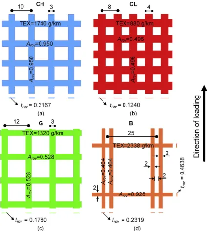
Three beams with shear span-to-depth ratios equal to 1.6 (CON_1.6), 2.6 (CON) and 3.6 (CON_3.6) were used as control specimens and tested, whereas the rest of the specimens were strengthened by U-shaped TRM jackets. Four different textile grids were used, two carbon (a light and a heavy-weight carbon textile), a glass and a basaltfibre textile.
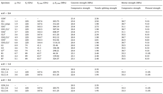
The details of the specimens are presented inTable 1.Fig. 2depicts all the strengthening schemes adopted in retrofitted specimens. The notation of strengthened specimens is Y1L1_Y2L2, where Y1 and Y2 denote thefirst and second (if any) textile reinforcement, respectively, and L1, L2 denote the number of TRM layers of thefirst and second (if any) textile reinforcement (CL for light-weight carbon, CH for heavy-weight carbon, G for glass and B for basalt), respectively. The suffix ‘strips’ was used for specimen strengthened with strips that were combined with continuous TRM layer. For beams witha/d different than 2.6, a suffix with the shear span-to-depth ratio (1.6 or 3.6) was used. The description of the retrofitted beams follows:
•
CL1 and CL3: beams witha/d= 2.6, strengthened with 1 and 3 light carbon TRM layers, respectively.•
CH1_CL1, CH2_CL1 and CH3_CL1: beams with a/d = 2.6, that strengthened with 1 light carbon TRM layer combined with 1, 2 and 3 heavy-weight carbon TRM layers, respectively.•
CL1_strips: beam witha/d = 2.6, that strengthened with 1 light carbon TRM layer combined with light carbon strips of 125 mm width, as shown inFig. 2.•
G1, G3 and G7: beams witha/d= 2.6, strengthened with 1, 3 and 7 glass TRM layers, respectively.•
B1, B3 and B7: beams witha/d= 2.6, strengthened with 1, 3 and 7 basalt TRM layers, respectively.•
CL1_1.6 and CL3_1.6: beams witha/d= 1.6, strengthened with 1 and 3 light carbon TRM layers, respectively.•
CL1_3.6 and CL3_3.6: beams witha/d= 3.6, strengthened with 1 and 3 light carbon TRM layers, respectively.2.2. Materials and strengthening procedure
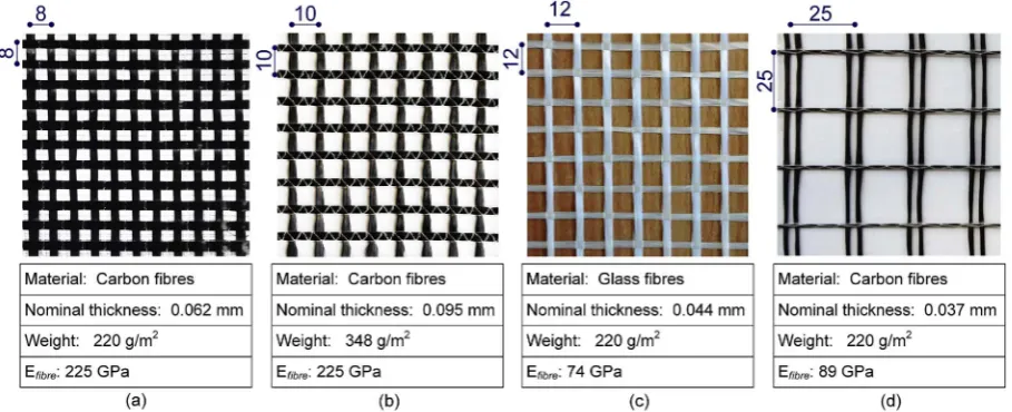
Casting of specimens was made by using the same concrete. The concrete compressive strength and the concrete tensile splitting strength were obtained by testing concrete cylinders (300 × 150 mm) on the day of testing the beams.Table 1summarizes the (average of 3 specimens) concrete strength values. The yield stress (average of 3 specimens) of longitudinal bars with 16 and 10 mm diameter was equal to 547 MPa and 552 MPa, respectively, whereas the yield stress of the steel bars with 8 mm diameter used for stirrups, was equal to 568 MPa. The four textile grid materials used in this study have equal amount offibres in two orthogonal directions. The weight of the light carbon, heavy carbon and glass textiles was equal to 220 g/m2, 348 g/m2and 220 g/m2, respectively, whereas the weight of basalt textile including 10% coating was 220 g/m2. The nominal thickness,t
f(based on the
Fig. 1.(a) Schematic test set-up; (b) cross-section (dimensions in mm).
Table 1
Strengthening configuration and material properties of all specimens.
Specimen ρf(‰) Ef(GPa) Ef_TRM(GPa) ρfEf_TRM(MPa) Concrete strength (MPa) Mortar strength (MPa)
Compressive strength Tensile splitting strength Compressive strength Flexural strength
a/d=2.6
CONa – – – 21.6 2.36 – –
CL1 1.2 225 167.6 203.75 23.0 2.50 38.7 9.10
CL1_strips 1.9 225 167.6 312.20 20.0 1.98 38.7 9.10
CH1a 1.9 225 163.3 304.19 23.8 2.73 31.1 10.3
CH1_CL1c 3.1 225 165.5 507.94 20.0 1.98 38.7 9.10
CH2a 3.7 225 163.3 608.37 23.8 2.73 31.1 10.3
CL3b 3.6 225 167.6 611.25 20.8 2.39 35.5 8.10
CH2_CL1c 4.9 225 164.7 812.12 20.0 1.98 38.7 9.10
CH3a 5.6 225 163.3 912.56 22.6 2.81 26.9 8.64
CH3_CL1c 6.8 225 164.4 1116.31 20.0 1.98 38.7 9.10
G1 0.9 74 41.1 35.46 20.0 1.98 35.5 8.10
G3 2.6 74 41.1 106.38 20.0 1.98 35.5 8.10
G7b 6.0 74 41.1 248.21 20.0 1.98 38.7 9.10
B1 0.7 89 63.7 46.34 23.1 2.48 33.3 11.05
B3 2.2 89 63.7 139.02 23.1 2.48 35.5 8.10
B7 5.1 89 63.7 324.37 23.1 2.48 35.5 8.10
a/d=1.6
CON_1.6 – – – 20.5 2.35 – –
CL1_1.6 1.2 225 167.6 203.75 22.6 1.95 33.3 11.05
CL3_1.6 3.6 225 167.6 611.25 22.6 1.95 33.3 11.05
a/d=3.6
CON_3.6 – – – 20.5 2.35 – –
CL1_3.6 1.2 225 167.6 203.75 22.6 1.95 33.3 11.05
CL3_3.6 3.6 225 167.6 611.25 22.6 1.95 33.3 11.05
aSpecimens included in Tetta et al. 2015[28]. bSpecimens included in Tetta and Bournas 2016[4]. cρ
[image:3.595.40.560.375.676.2]A polymer-modified cementitious mortar was used as matrix of the TRM composite material which was the same for all four textile mate-rials. The cement-to-polymers ratio was equal to 8:1, whereas the water-to-cement ratio was equal to 0.23. The strength properties (average values of 3 specimens) of the mortar experimentally obtained
through prisms on the day of testing according to the EN 1015-11[54] are summarized inTable 1.
[image:4.595.72.526.56.412.2]As shown inFig. 4a, before the application of TRM jacketing, the concrete surface was properly prepared by grinding the concrete sur-face and creating a grid grooves. To avoid stress concentration, the two
Fig. 2.Schematic representation of different strengthening configurations.
[image:4.595.72.527.507.692.2]bottom edges of each specimens were rounded (radius equal to 15 mm). The first 2 mm-thick mortar layer was applied on the (dampened) concrete surface by using a smooth metal trowel. The first layer of textile was applied after the application of thefirst mortar layer and then pressed slightly into the mortar by hand pressure to fully immerse thefibre roving (Fig. 4b). A layer of mortar was then applied to com-pletely cover the textile. The rest textile layers were applied by fol-lowing the aforementioned procedure (Fig. 4c). It is very important in this method to apply each layer of mortar while the previous layer is still fresh.
2.3. Tensile tests in TRM coupons
Three (dumbbell) tensile coupons for each textile mesh material with the geometry shown in Fig. 5a were prepared and tested at a monotonic displacement rate of 0.02 mm/s to characterise the tensile behaviour of the composite material. A universal testing machine of 200 kN load-capacity was used for conducting the uniaxial tensile testing. Two LVDTs were attached on the coupon (one on each side) to measure its axial deformation (Fig. 5b). The response of all TRM cou-pons comprised three distinct stages:
(1) the specimen remains uncracked
(2) development of multiple cracks after thefirst cracking occurs (3) the cracking pattern has fully developed and the increase in
re-sistance is due to the textile itself until rupture offibres is observed. Table 2includes the mean values of ultimate tensile stress (ffu),
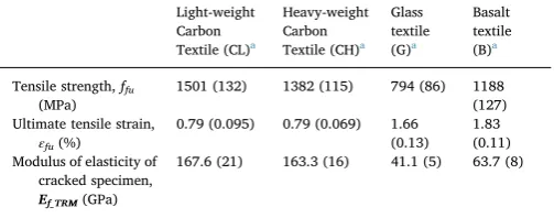
ultimate tensile strain (εfu) and the modulus of elasticity at the cracked
stage,Ef_TRMthat is the secant modulus of elasticity of the 3rd branch of
the stress-strain curve. The modulus of elasticity of the TRM jacket,
Ef_TRM, for each beam is also included inTable 1.
2.4. Experimental setup and procedure
As shown inFig. 6, the beams were tested under three-point bending monotonic loading at a displacement rate of 0.02 mm/s using a stiff steel reaction frame. The load was applied using a 500 kN-capacity servo-hydraulic actuator that was vertically positioned. An external LVDT was used to measure the vertical displacement at the load ap-plication position as illustrated in Fig. 6; the displacement measure-ments from this LVDT was used in load versus displacement curves, presented in Section3. Moreover, the Digital Image Correlation (DIC) method was also used to monitor the field of displacements within strengthening zone, using two high-resolution cameras.
3. Experimental results
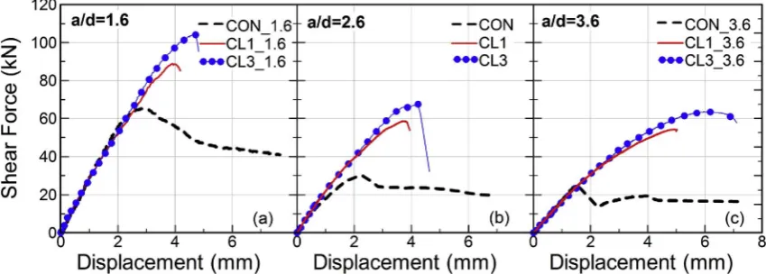
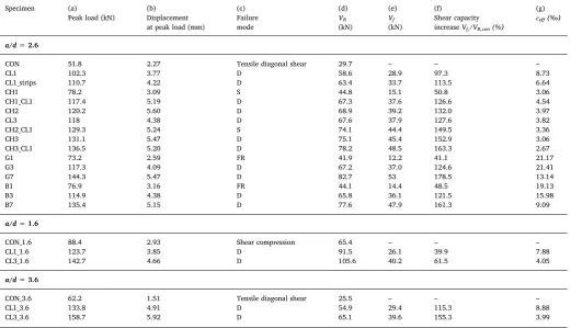
The load versus displacement curves of all beams witha/d= 2.6 strengthened with carbon, glass and basalt TRM jackets are presented in Fig. 7a–c, respectively, whereas the shear force versus displacements curves of the beams with differenta/dratios are included inFig. 8a–c. Table 3includes:
(a) The ultimate load
(b) the displacement corresponding at the ultimate load (c) the observed failure mode
(d)VR, which is the shear resistance of the critical shear span
(e) the contribution of the TRM jacket to the shear resistance of the beam,Vf
(f) The increase in the shear capacity owing to TRM jacketing, Vf/ VR,con(%)
(g) the effective strain of the TRM jacket, εeff,(‰) which is defined using the following equation:
=
εeff Vf/(ρ Ef f TRMbw0.9 )d (1)
It is worth mentioning that the calculation ofVfvalues and therefore εeffvalues has been based on the simplified hypothesis that the two
mechanisms of carrying forces (concrete contribution and jacket con-tribution) are superimposed without considering any interaction be-tween them. The interaction bebe-tween mechanisms of carrying forces is more pronounced when stirrups are used[55,56].
The control beam witha/d= 2.6 (CON) failed in shear at a peak load of 51.8 kN, when a large shear crack opened in the critical shear span. (Fig. 7a).
Specimens CH1 and CH2 reached an ultimate load of 78.2 and 120.2 kN, respectively, resulting in 50.8% and 132% shear capacity increase. Failure of specimen CH1 was due to slippage of the fibre rovings through the mortar and rupture of thefibres at the outer layer of the roving along the shear crack (Fig. 9a). In specimen CH2 the TRM jacket was debonded with part of concrete at a large area of the critical shear span (Fig. 9b).
Specimens CL1, CL1_strips, CH1_CL1, CL3, CH2_CL1, CH3 and
Fig. 4.(a) Prepared concrete surface before strengthening; (b) impregnation of the textile
CH3_CL1 failed in shear at a peak load 102.3, 110.7, 117.4, 118, 129.3, 131.1 and 136.5 kN, respectively, which yields 97.3%, 113.5%, 132%, 127.6%, 149.5%, 152.9% and 163.3% shear capacity increase, respec-tively. In all these beams TRM jacket was debonded from the concrete substrate at the full-length of the shear span with part of the concrete cover (Fig. 9c–i).
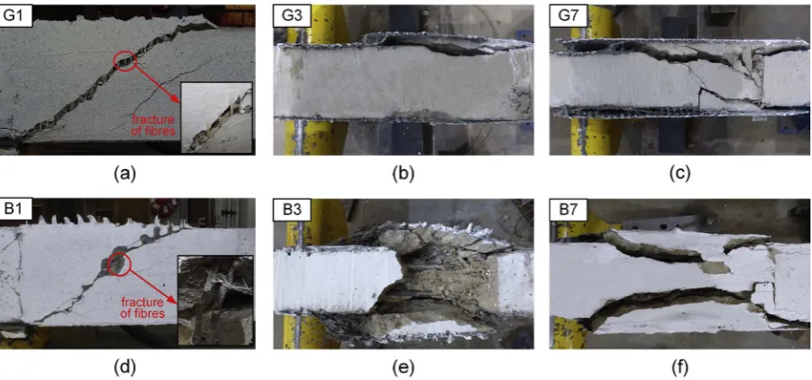
The peak load attained by specimens G1, G3, G7, B1, B3 and B7 was 73.2, 117.3, 144.3, 76.9, 114.9 and 135.4 kN, respectively, which yields 41.1%, 124.6%, 178.5%, 48.5%, 121.5% and 161.3% increase in the shear capacity, respectively. Failure of specimens G1 and B1 was due to fracture of the textilefibres crossing the shear crack (Fig. 10a and d), whereas in specimens G3, G7, B3 and B7 TRM jacket was de-bonded with part of the concrete cover (Fig. 10b–c, e–f).
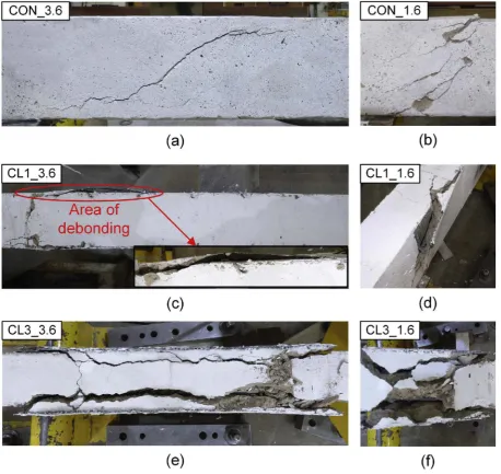
The control beams witha/d= 1.6 and with a/d= 3.6 failed in shear at an ultimate load of 88.4 and 62.2 kN, respectively. In specimen CON_3.6 a large shear crack was formed at the critical shear span
(Fig. 11a) similar to the control specimen witha/d = 2.6. On the contrary, specimen CON_1.6, with the smallest shear-span-to depth ratio, failed in shear compression (Fig. 11b). Finally, specimens CL1_1.6, CL3_1.6, CL1_3.6 and CL3_3.6 reached an ultimate load of 123.7, 142.7, 133.8 and 158.7 kN, respectively, resulting in 39.9%, 61.5%, 115.3% and 155.3% shear capacity increase, respectively. These specimens failed in the same way with their counterpart specimens with
a/d = 2.6, namely full detachment of the jacket from the substrate including part of the concrete cover. In specimen CL1_3.6, the de-bonding was initiated at the load application position and progressed towards the area below the shear crack (Fig. 11c), whereas in speci-mens CL1_1.6, CL3_3.6 and CL3_1.6, the TRM jackets debonded at the full-length of the shear span as shown inFig. 11d–f, respectively.
4. Discussion
All beams failed in shear as designed and therefore the capacity of all retrofitting configurations in increasing the shear resistance of the beams was successfully evaluated. The results of this experimental programme were examined in terms of shear capacity increase and failure modes observed, revealing the following information for the various parameters investigated in this study.
4.1. Effect of external reinforcement ratio and axial rigidity
Fig. 12a–b plots the experimentally obtained effective strains,εeff,
against the ρf andρf Ef_TRM values, respectively {ρfEf_TRM values
[image:6.595.36.350.58.348.2]re-present the axial rigidity of the strengthening layers (that constitutes an important parameter[57,58]), because the width of all beams is the same} for the beams retrofitted with carbon-fibre TRM jackets. Results from three FRP-retrofitted beams presented in Refs. [4,42] (having identical geometry with the beams tested here), are also included in the
[image:6.595.38.290.385.484.2]Fig. 5.Three-point bending test set-up of beams.
Table 2
Summary of TRM coupons results.
Light-weight Carbon Textile (CL)a
Heavy-weight Carbon Textile (CH)a
Glass textile (G)a
Basalt textile (B)a
Tensile strength,ffu
(MPa)
1501 (132) 1382 (115) 794 (86) 1188
(127) Ultimate tensile strain,
εfu(%)
0.79 (0.095) 0.79 (0.069) 1.66
(0.13) 1.83 (0.11) Modulus of elasticity of
cracked specimen,
Ef_TRM(GPa)
167.6 (21) 163.3 (16) 41.1 (5) 63.7 (8)
Fig. 6.(a) Geometry of TRM coupons; (b) test set-up for tensile testing of TRM coset-upons; (c) stress versus strain curves.
[image:7.595.85.510.530.682.2]Fig. 7.Load versus vertical displacement curves for all tested specimens of 2.6 shear span-to-depth ratio.
plot ofFig. 12a–b for comparisons. AlsoTable 4includes all the im-portant results of the three FRP-strengthened beams, presented in Refs. [4,48]. From the comparison inFig. 12a–b, it becomes evident that TRM is as effective as FRP jacketing in increasing the shear capacity of concrete beams, when failure is associated to debonding of the jacket. In specific, for this type of failure the trend of the experimentalεeff
values for TRM jackets is descending for increasing ρfEf_TRMvalues,
which is in agreement with the typical behaviour of FRP jackets. As also shown inFig. 12b, TRM consisting of heavy-carbonfibre textile is less effective than equivalent FRP system (in terms ofρfEf_TRM) or TRM
consisting of light-carbonfiber textile, when premature failure due to slippage offibres occurs.
Fig. 12c–d plots the experimental effective strains versus, εeff,
against theρfandρfEf_TRMvalues, respectively for beams strengthened
with glass and basalt TRM U-shaped jackets. In case of low ρfEf_TRM
values (ρfEf_TRM< 100 MPa), failure of specimens is associated with the
rupture of thefibres (basalt or glass) in the TRM jackets, resulting in full exploitation of the tensile capacity of the textiles. Increasing the ρf Ef_TRMvalues, debonding failure was experienced (TRM jacket was
de-bonded with part of concrete cover). As in the case of carbon textiles, the trend of the experimentalεeffvalues for glass and basalt TRM jackets
is also descending for increasing ρf values, when debonding of the
jacket was experienced.
4.2. Effect of textile geometry
In this section the effect of the geometry of the textilefibre material
on the failure mode and performance of TRM jackets is studied. The effect of the textile geometry on the behaviour of specimens strength-ened with equivalent (in terms ofρf) carbon TRM jackets isfirst
dis-cussed, whereas the effect on the failure mode of beams strengthened with one TRM layer of different textile material (carbon, glass and basalt) follows next.
Specimens CL1_strips and CH1 had the same reinforcement ratio (equal to 1.9‰), comprising TRM jackets with carbon textiles of dif-ferent geometry (seeFig. 2). Following the same concept, specimens CL3 and CH2 strengthened with correspondingly 3 and 2 layers of light and heavy carbon textile, having the same reinforcement ratio (ρf≈3.6‰).Fig. 13a and b depicts the mesh pattern of both heavy and
light carbonfibre textiles, respectively. It can be observed that the combination of wider rovings (4 mm) with smaller mesh size (8 mm) in the light carbon textile (Fig. 13b), allows for a denser mesh-pattern when compared to the heavy carbon textile with 3 mm-wide rovings and 10 mm-mesh.
By comparing the results of specimens CH1 and CL1_strips, it is shown that the geometry of the textilefibre material has a strong effect on the failure mode and as a result on the shear capacity of beams in case of low external reinforcement ratio (ρf≈1.9‰). As mentioned in
[image:8.595.39.561.81.380.2]Section3, specimen CH1 failed due to slippage offibres through the mortar and rupture offibres at the outer layer of roving along the shear crack contrary to the failure of specimen CL1_strips that was attributed to debonding of the TRM jacket with part of concrete cover. The in-crease in shear capacity of specimens CH1 and CL1_strips, was 50.8% and 113.5%, respectively, whereas the effective strains for specimens
Table 3
Summary of test results.
Specimen (a)
Peak load (kN)
(b) Displacement at peak load (mm)
(c) Failure mode (d) VR (kN) (e) Vf (kN) (f) Shear capacity increaseVf,/VR,con(%)
(g)
εeff(‰)
a/d=2.6
CON 51.8 2.27 Tensile diagonal shear 29.7 – – –
CL1 102.3 3.77 D 58.6 28.9 97.3 8.73
CL1_strips 110.7 4.22 D 63.4 33.7 113.5 6.64
CH1 78.2 3.09 S 44.8 15.1 50.8 3.06
CH1_CL1 117.4 5.19 D 67.3 37.6 126.6 4.54
CH2 120.2 5.60 D 68.9 39.2 132.0 3.97
CL3 118 4.38 D 67.6 37.9 127.6 3.82
CH2_CL1 129.3 5.24 S 74.1 44.4 149.5 3.36
CH3 131.1 5.47 D 75.1 45.4 152.9 3.06
CH3_CL1 136.5 5.20 D 78.2 48.5 163.3 2.67
G1 73.2 2.59 FR 41.9 12.2 41.1 21.17
G3 117.3 4.09 D 67.2 37.0 124.6 21.41
G7 144.3 5.47 D 82.7 53 178.5 13.14
B1 76.9 3.16 FR 44.1 14.4 48.5 19.13
B3 114.9 4.38 D 65.8 36.1 121.5 15.98
B7 135.4 5.15 D 77.6 47.9 161.3 9.09
a/d=1.6
CON_1.6 88.4 2.93 Shear compression 65.4 – – –
CL1_1.6 123.7 3.85 D 91.5 26.1 39.9 7.88
CL3_1.6 142.7 4.66 D 105.6 40.2 61.5 4.05
a/d=3.6
CON_3.6 62.2 1.51 Tensile diagonal shear 25.5 – – –
CL1_3.6 133.8 4.91 D 54.9 29.4 115.3 8.88
CL3_3.6 158.7 5.92 D 65.1 39.6 155.3 3.99
Fig. 9.Failure modes of carbon TRM-retrofitted specimens of 2.6 shear span-to-depth ratio: (a) specimen CH1–local damage of the jacket; (b) specimen CH2–debonding of the jacket over a large area of the shear span: peeling offof the concrete cover; (c)–(j) specimens CL1, CL1_strips, CH1_CL1, CL3, CH2_CL1, CH3_CL1 - abrupt debonding of the TRM jacket over the whole area of the shear span: peeling offof the concrete cover.
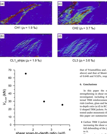
[image:9.595.74.525.438.649.2]CH1 and CL1_strips were 3.06‰and 6.64‰, respectively.Fig. 14a–d depictfield of the vertical deformations of the TRM jackets at the in-stant of ultimate load, obtained using DIC system. FromFig. 14a, it is evident that in specimen CH1, the TRM jacket deformed only along the main and secondary shear cracks, whereas the rest part of the jacket was not activated. On the contrary, in specimen CL1_strips (Fig. 14b), the distribution of deformations was better, indicating that the jacket was activated over a broader area due to favourable redistribution of stresses. The superior performance of the light carbon textile is possibly associated with the better fibres distribution along the shear span (denser mesh-pattern of the textile), which in turn improves the me-chanical interlock between the textile reinforcement and the matrix.
Specimens CH2 and CL3 both failed due to debonding of the TRM jacket, with similar shear capacity increase (132% and 127.6%, re-spectively). As shown inFig. 14candd, in both specimens the vertical
deformations were distributed over a broad region of the shear span. Thus, the increase of external reinforcement ratio,ρf(through the
in-crease of the number of layers), eliminated the effect of the textile geometry.
[image:10.595.70.529.58.491.2]cement paste is higher, resulting in improved bond characteristics. On the other hand, textiles with bigger roving size are more prone to slippage of thefibre rovings through the matrix, unless they are coated, as in the case of the basalt textile used in this study.
4.3. Effect of shear span-to-depth ratio (a/d)
Fig. 15illustrates the effect of the shear span-to-depth ratio (a/d) on the shear resistance of the unretrofitted specimens,VR,con. It is
well-known that increasing thea/dratio the shear resistance decreases; this was also verified in this study, as shown inFig. 15. This behaviour is explained through the different load-carrying mechanisms in each case. In specific, the arch action is the dominant mechanism of shear re-sistance in unretrofitted beams with lowa/dratio (i.e.a/d= 1.6, deep beams), whereas beam action (truss analogy mechanism) is developed in beams of high shear span-to-depth ratios (a/d= 2.6 and 3.6).
A comparison between specimens CL1_1.6, CL3_1.6, CL1, CL3, CL1_3.6 and CL3_3.6 shows that the a/d ratio had no effect on the failure mode of specimens strengthened with the same TRM jackets. All specimens failed due to debonding of the TRM jacket with peeling offof the concrete cover. In specific, when 3 TRM layers were applied in specimens of anya/dratio, the part of concrete that peeled offfrom the substrate was thicker with respect to the specimens strengthened with 1
TRM layer (Fig. 11c–f).Fig. 16presents images of the in-plane vertical deformations of the TRM jackets in beams of different shear spans, obtained through DIC measurements at the instant of peak load. In general, vertical deformations of TRM jackets with both 1 and 3 light-carbon TRM layers were distributed over a broad area of the shear span for all beams of different sheara/dratios as a result of the good me-chanical interlocking characteristics and the small roving size of the light carbon textile.
Fig. 17a illustrates the effect of thea/dratio on the contribution of the jacket to the total shear capacity,Vf, for two different external
re-inforcement ratios (ρf= 1.2‰and ρf = 3.6‰). The a/d ratio has
practically no effect on theVfvalues for TRM jackets regardless the
external reinforcement ratio.Fig. 17b illustrates the effect of thea/d
ratio on the shear capacity enhancement (Vf/VR,con × 100%) for two
different external reinforcement ratios (ρf= 1.2‰andρf= 3.6‰). The
shear capacity enhancement considerably increases witha/d. This is attributed to the reduced shear resistance of the unretrofitted specimens when increasing thea/dratio (Fig. 15).
5. Comparison between experimental results and analytical models
[image:11.595.56.538.56.275.2]Based on the results of this paper and previous studies of the
Fig. 12.Experimentally obtained effective strains versusρfvalues andρfEf_TRMvalues for specimens strengthened with carbon TRM and FRP U-jackets (a–b) and specimens strengthened
[image:11.595.37.559.625.684.2]with glass and basalt TRM U-jackets (c–d).
Table 4
Summary of FRP-strengthened specimens results.
Specimen ρf(‰) Ef(GPa) Ef_ FRP
(GPa)
Ultimate tensile strain,εfu(%) Ultimate tensile strength,ffu(MPa) Peak Load (kN) Vf(kN) εeff(‰)
CH1_Ra 1.9 225 200.7 1.261 2788.4 113.4 35.3 5.81
CH2_Ra 3.7 225 200.7 1.261 2788.4 126.2 42.6 3.51
CH3_Rb 5.6 225 200.7 1.261 2788.4 139.0 49.9 2.74
authors, TRM jackets are as effective as FRP jackets when local damage of the TRM jackets (slippage of verticalfibres through the mortar and rupture of the outerfibres of the roving along the shear crack) is pre-vented and failure is attributed to debonding of the TRM jacket. Therefore, the formulas that have been developed so far for predicting the shear contribution of FRP U-jackets,Vf, to the total shear resistance
of beams, could be also used for TRM jackets when failure is due to debonding. Three different models, namely those of Triantafillou and Antonopoulos (2000), [59](provisions offib2001[60]are based on this model), Chen and Teng (2003), [61](the Australian guidelines provisions, CIDAR (CT) Design Proposal (2006)[62]are based on this
model) and Monti and Liotta (2007),[63](the Italian guidelines pro-visions, CNR Design Proposal (2004)[64] are based on this model) were used for the prediction ofVfvalues for both TRM and FRP jackets.
The results are presented inTable 5, and are supported byFig. 18. The methodology to estimate the FRP or TRM contribution in shear, Vf,
according to each of the aforementioned models is briefly presented in theAppendix. The modulus of elasticity offibres,Ef, (Table 1), was used
in these calculations.
The comparison between the experimental and predictedVfvalues
[image:12.595.85.510.54.529.2]is presented inTable 5(usingθ= 45° andβ= 90°) for specimens failed due to debonding of the TRM or FRP jacket. The model of Triantafillou
and Antonopoulos (2000) is not applicable for specimens reinforced by either glass or basalt TRM jackets. In general, all three models under-estimate theVfvalues, and therefore they give conservative predictions.
The models of Chen and Teng (2003) and Monti and Liotta (2007), that are applicable for glass and basalt TRM jackets, considerably under-estimate the contribution of glass and basalt TRM jackets.
In particular, the model of Chen and Teng (2003) is the best in terms of average ratio of predicted to experimental peak load (Vf,pre/ Vf,exp= 0.741); it has however a coefficient of variation (CoV) value
equal to 16.9%. The model of Triantafillou and Antonopoulos (2000) is the 2nd best among the three, withVf,pre/Vf,expequal to 0.715 but is has
the lowest CoV = 12%, whereas model of Monti and Liotta (2007) has
Vf,pre/Vf,exp= 0.598 and CoV = 18.6%. When only the carbonfibre
textiles are considered, the Chen and Teng (2003) is the best both terms of average ratio ofVf,pre/Vf,exp= 0.801 and CoV = 8.98%, followed by
that of Triantafillou and Antonopoulos (2000, corresponding values as above) and that of Monti and Liotta (2007) with corresponding values of 0.648 and 9.52%, respectively.
6. Conclusions
In this paper the effectiveness of U-shaped TRM jackets for strengthening in shear rectangular concrete beams was experimentally investigated, including the following parameters: the amount of ex-ternal TRM reinforcement ratio (ρf) using three different textile
mate-rials (carbon, glass and basalt), the textile geometry and the shear span-to-depth ratio (a/d) in RC rectangular beams strengthened in shear with U-shaped TRM jackets. For this purpose, 22 shear-deficient beams were tested under monotonic three-point loading. The primary conclusions of this paper are summarized as follows:
•
Carbon TRM U-jackets are as effective as carbon FRP U-jackets in increasing the shear capacity of beams, when failure is attributed to full debonding of the jacket with part of the concrete cover attached to it.•
The experimental effective strain values,εeff, for carbon, glass orbasalt TRM jackets are generally decreasing for increasing axial ri-gidity (ρfEf_TRM), when failure is associated with debonding of the
TRM jacket, which is in agreement with the typical behaviour of FRP jackets.
•
In case of lowρfEf_TRMvalue, different carbonfibre textile geome-tries having the sameρfEf_TRMvalue result in different load increase and failure mode. The effect of the geometry of the textile fibre material is drastically mitigated by increasing theρfEf_TRMvalue.•
The textile roving geometry affects the performance of TRM jackets in case of low axial rigidity. In particular, textiles with smaller roving area arranged in a denser pattern result in better bond characteristics between the textile and the mortar, and hence im-proved efficiency.•
The shear span-to-depth ratio has no effect on both the failure mode and the contribution of the jacket to the total shear resistance of the beams. [image:13.595.41.397.53.500.2]Future research could be directed towards developing a reliable design approach for the contribution of TRM jackets to the shear ca-pacity of concrete beams.
Fig. 14.Field of vertical axis deformations in the critical shear span of TRM-retrofitted specimens: (a) CH1; (b) CL1_strips; (c) CH2; (d) CL3 at the instant of peak load.
Fig. 16.Field of vertical axis deformations in the critical shear span of TRM-retrofitted specimens: (a) CL1_1.6; (b) CL3_3.6; (c) CL1; (d) CL3; (e) CL1_1.6; (f) CL3_3.6 at the instant of peak load.
Fig. 17.Effect of shear span-to-depth ratio on: (a) the contribution of the jacket to the total shear resistance,Vf; (b) the shear capacity enhancement,Vf/VR,con(%).
Table 5
Comparison between experimental and predictedVfvalues.
Analytical Results
Triantafillou and Antonopoulos (2000)
Chen and Teng (2003) Monti and Liotta (2007)
Vf,exp(kN) Vf,pre
(kN)
Vf,pre/ Vf,exp
Vf,pre
(kN)
Vf,pre/ Vf,exp
Vf,pre
(kN)
Vf,pre/ Vf,exp
CL1 28.9 16.5 0.570 21.8 0.755 18.1 0.625
CL1_strips 33.7 22.1 0.655 25.2 0.748 19.5 0.578
CL1_CH1 37.6 27.5 0.731 30.5 0.811 23.6 0.628
CH2 39.2 31.9 0.814 34.5 0.881 29.9 0.762
CL3 37.9 30.1 0.793 32.8 0.866 27.3 0.720
CL1_CH2 44.4 33.9 0.763 36.0 0.811 28.0 0.630
CH3 45.4 37.4 0.824 39.0 0.860 34.7 0.763
CL1_CH3 48.5 39.0 0.804 39.7 0.819 30.9 0.637
[image:14.595.43.557.567.736.2]Acknowledgements
This work was supported by the Engineering and Physical Sciences Research Council [grant number EP/L50502X/1]. The authors wish
thank the technical staffat the University of Nottingham Tom Buss, Mike Langford, Nigel Rook, Balbir Loyla, Gary Davies, Sam Cook and Luke Bedford, the student Yuchao Shang and Dr. Saad Raoof for their assistance to the experimental work.
Appendix
Vfcalculation methodology
1. Triantafillou and Antonopoulos (2000)
= +
Vf 0.9dρ E ε bf f eff w(sinβ cos )β
For U-shaped jackets
= ⎧
⎨ ⎪
⎩ ⎪
⎛ ⎝
⎞ ⎠
⎛ ⎝
⎞ ⎠
−
ε
ε
min 0.17
0.65 10
eff
f
ρE fu
f
ρE
0.3
0.56 3 c
f
c f 2/3
2/3
[image:15.595.44.557.74.472.2]2. Chen and Teng (2003)
Fig. 18.Experimental versus analyticalVfvalues. Table 5(continued)
Analytical Results
Triantafillou and Antonopoulos (2000)
Chen and Teng (2003) Monti and Liotta (2007)
Vf,exp(kN) Vf,pre
(kN)
Vf,pre/ Vf,exp
Vf,pre
(kN)
Vf,pre/ Vf,exp
Vf,pre
(kN)
Vf,pre/ Vf,exp
B7 47.9 NA NA 27.0 0.563 22.4 0.467
CL1_1.6 26.1 16.1 0.615 21.0 0.805 16.2 0.619
CL3_1.6 40.2 29.7 0.740 32.5 0.809 25.1 0.623
CL1_3.6 29.4 16.1 0.546 21.0 0.715 16.2 0.550
CL3_3.6 39.6 29.7 0.751 32.5 0.822 25.1 0.633
CH1_R 35.3 22.5 0.636 26.4 0.747 22.5 0.638
CH2_R 42.6 31.9 0.749 34.5 0.811 29.9 0.701
CH3_R 49.9 36.3 0.727 37.9 0.760 30.5 0.611
Mean 0.715 0.741 0.598
CoV (%) 12.0 16.9 18.6
Average absolute error % 28.5 25.9 40.2
Mean for carbonfibre textiles 0.715 0.801 0.648
CoV (%) for carbonfibre textiles 12.0 5.98 9.52
[image:15.595.38.558.302.470.2]=
ffed D ff fed,max
= ⎧ ⎨ ⎪ ⎩ ⎪ ⎛ ⎝ ⎜ ⎞ ⎠ ⎟ ≤ − > = − −
( )
( )
D λ λλ L L
, 1
1 , 1
where /
f πλ
π πλ
e
2 1 cos
sin 2 max πλ πλ 2 2
For U-shaped jacketsLmax=0.9d
= L t f E e f c = ⎧ ⎨ ⎩
f β β
ϕ f
min 0.427
fed w l
f
t
R fu
,max
Ef c
=⎧
⎨ ⎩
≥
< = =
( )
β λ
λ β ϕ
1, 1
sin , 1, 0.707 for continuous sheets and 0.8
l πλ w R
2
3. Monti et Liotta (2007)
= +
Vf 2ffed ft 0.9 (cotd θ cot )β
=
L E t f 2 e f ct = = =
f E Γ
t Γ k f f k
0.8 2 , where 0.03 , 1 for continuous sheets
fdd
f fk
f
fk b c ct b
For U-shaped jacketsLb=0.9d IfLb<L fe⋅fdd L =ffdd
(
2−)
L L
L L
(b) b e b e ⎜ ⎟ = ⎛ ⎝ − ⎞ ⎠
f f L L β
d h
( ) 1 sin
3 min(0.9 , )
fed fdd b e
w
Notation
Arov roving area
Df Stress distribution factor Ef Modulus of elasticity of thefibers
Ef_FRP Modulus of elasticity of the FRP specimen
Ef_TRM Modulus of elasticity of the cracked TRM specimen
Lb Available bond length Le Effective bond length Lmax Available bond length
Vf Contribution of strengthening to the shear capacity of the beam VR Shear force in the critical span at peak load
VR,con Shear resistance of the control specimen
VR,str Shear resistance of the strengthened specimen
bw Width of the beam
d Effective depth of the section
dfb Bottom end of the effective (TRM or FRP jacket)
dft Coordinate of the top end of the effective (TRM or FRP jacket) fc Compressive strength of concrete
fct Tensile splitting strength of concrete
ffdd Design value for the FRP or TRM debonding stress ffdd(Lb) Reduced design value for the FRP or TRM debonding stress ffed Design value for the FRP or TRM effective stress
ffed,max Maximum design stress in FRP or TRM
ffu Ultimate strength of TRM or FRP jacket hfe Effective height of the bonded reinforcement hw Height of T-beam's web
β Fibre angle direction with respect to the longitudinal axis of the beam βl Bond length coefficient
βw Strip width coefficient εeff Effective strain εfu Ultimate tensile strain
θ Angle between the shear crack and the axis of the beam λ Normalized maximum bond length
ρf Geometrical reinforcement ratio of the composite material which is expressed as 2tf/bw
φR Reduction factor due to local stress in corners
References
[1] Triantafillou TC, Papanicolaou CG. Shear strengthening of reinforced concrete members with textile reinforced mortar (TRM) jackets. Mater Struct 2006;39(1):93–103.
[2] Bournas DA, Lontou PV, Papanicolaou CG, Triantafillou TC. Textile-reinforced mortar versusfiber-reinforced polymer confinement in reinforced concrete col-umns. ACI Struct J 2007;104(6).
[3] Carloni C, Bournas DA, Carozzi FG, D'Antino T, Fava G, Focacci F, et al. Fiber re-inforced composites with cementitious (inorganic) matrix [Chapter 9]. In: Pellegrino C, Sena-Cruz J, editors. Design procedures for the use of composites in strengthening of reinforced concrete structures–state of the art report of the RILEM TC 234-DUCSpringer, RILEM STAR Book Series; 2015. p. 349–91.
[4] Tetta ZC, Bournas DA. TRM versus FRP jacketing in shear strengthening of concrete members subjected to high temperature. Compos Part B 2016;106:190–205.http:// dx.doi.org/10.1016/j.compositesb.2016.09.026.
[5] Raoof S, Koutas L, Bournas D. Bond between TRM versus FRP composites and concrete at high temperatures. Compos Part B Eng 2017;127:150–65.
[6] Raoof S, Bournas DA. TRM versus FRP inflexural strengthening of RC beams: be-haviour at high temperatures. Elsevier Construction and Building Materials 2017;154:424–37.
[7] D'Ambrisi A, Feo L, Focacci F. Experimental analysis on bond between PBO-FRCM strengthening materials and concrete. Compos Part B Eng 2013;44(1):524–32. [8] Raoof S, Koutas L, Bournas D. Bond between textile-reinforced mortar (TRM) and
concrete substrates: experimental investigation. Compos Part B 2016;98:350–61.
http://dx.doi.org/10.1016/j.compositesb.2016.05.041.
[9] Jesse F, Weiland S, Curbach M. Flexural strengthening of RC structures with textile-reinforced concrete. American Concrete Institute; 2008. p. 49–58. Special Publication 250.
[10] Sneed LH, Verre S, Carloni C, Ombres L. Flexural behaviour of RC beams strengthened with steel-FRCM composite. Eng Struct 2017;127:686–99. [11] Raoof S, Koutas L, Bournas D. Textile-reinforced mortar (TRM) versusfi
bre-re-inforced polymers (FRP) inflexural strengthening of RC beams. Constr Build Mater 2017;151:279–91.
[12] D’Ambrisi A, Focacci F. Flexural strengthening of RC beams with cement based
composites. J Comp Constr 2011.
http://dx.doi.org/10.1061/(ASCE)CC.1943-5614.0000218, 707-720.
[13] Elsanadedy HM, Almusallam TH, Alsayed SH, Al-Salloum YA. Flexural strength-ening of RC beams using textile reinforced mortar–Experimental and numerical study. J Comp Struct 2013;97:40–5.
[14] Koutas LN, Bournas DA. Flexural strengthening of two-way RC slabs with textile-reinforced mortar: experimental investigation and design equations. J Compos
Constr 2016.http://dx.doi.org/10.1061/(ASCE)CC.1943-5614.0000713.
[15] Alabdulhady MY, Sneed LH, Carloni C. Torsional behaviour of RC beams strengthened with PBO-FRCM composite–An experimental study. Eng Struct 2017;136:393–405.
[16] Bournas DA, Triantafillou TC, Zygouris K, Stavropoulos F. Textile-reinforced mortar versus FRP Jacketing in seismic retrofitting of RC columns with continuous or Lap-spliced deformed bars. J Comp Constr 2009;13(5):360–71.
[17] Bournas DA, Triantafillou TC. Bond strength of lap-spliced bars in concrete confined with composite jackets. J Comp Constr 2011;15(2):156–67.
[18] Bournas DA, Triantafillou TC. Bar buckling in RC columns confined with composite materials. J Comp Constr 2011;15(3):393–403.
[19] Bournas DA, Triantafillou TC. Biaxial bending of reinforced concrete columns strengthened with externally applied reinforcement in combination with confi ne-ment. ACI Struct J 2013;110(2):193.
[20] El-Maaddawy T, El Refai A. Innovative repair of severely corroded T-beams using fabric-reinforced cementitious matrix. J Compos Constr 2015;20(3). 04015073. [21] Papanicolaou CG, Triantafillou TC, Lekka M. Externally bonded grids as
strength-ening and seismic retrofitting materials of masonry panels. Constr Build Mater 2011;25(2):504–14.
[22] Harajli M, El Khatib H, San-Jose J. Static and cyclic out-of-plane response of ma-sonry walls strengthened using textile-mortar system. J Mater. Civ Eng 2010;22(11):1171–80.
[23] Koutas L. and Bournas D.A. Out-of-Plane Strengthening of Masonry-Infilled RC Frames with Textile-Reinforced Mortar Jackets. Elsevier Construction and Building Materials, 2018; submitted.
[25] Koutas LN, Bousias SN, Triantafillou TC. Seismic strengthening of masonry-infilled RC frames with TRM: experimental study. J Comp Constr 2015;19(2).http://dx.doi. org/10.1061/(ASCE)CC.1943-5614.0000507. 04014048.
[26] Triantafillou TC, Karlos K, Kefalou K, Argyropoulou E. An innovative structural and energy retrofitting system for URM walls using textile reinforced mortars combined with thermal insulation: mechanical andfire behaviour. Constr Build Mater 2017;133:1–13.
[27] Bournas DA. Strengthening of existing structures: selected case studies. In: Triantafillou TC, editor. Textilefibre composites in civil engineering Elsevier, Woodhead Publishing Limited; 2016. p. 389–411.http://dx.doi.org/10.1016/ B978-1-78242-446-8.00018-5. Ch. 17.
[28] Carabba L, Santandrea M, Carloni C, Manzi S, Bignozzi MC. Steelfiber reinforced geopolymer matrix (S-FRGM) composites applied to reinforced concrete structures for strengthening applications: a preliminary study. Compos Part B
2017;128:83–90.
[29] Valvona F, Toti J, Gattulli V, Potenza F. Effective seismic strengthening and mon-itoring of a masonry vault by using glassfiber reinforced cementitious matrix with embeddedfiber bragg grating sensors. Compos Part B 2017;113:355–70. [30] Donnini J, Basalo FDC, Corinaldesi V, Lancioni G, Nanni A. Fabric-reinforced
ce-mentitious matrix behavior at high-temperature: experimental and numerical re-sults. Compos Part B 2017;108:108–21.
[31] Bilotta A, Ceroni F, Lignola GP, Prota A. Use of DIC technique for investigating the behaviour of FRCM materials for strengthening masonry elements. Compos Part B 2017;129:251–70.
[32] Caggegi C, Carozzi FG, De Santis S, Fabbrocino F, Focacci F, Lanoye E, et al. Experimental analysis on tensile and bond properties of PBO and aramid fabric reinforced cementitious matrix for strengthening masonry structures. Compos Part B 2017;127:175–95.
[33] Caggegi C, Lanoye E, Djama K, Bassil A, Gabor A. Tensile behaviour of a basalt TRM strengthening system: influence of mortar and reinforcing textile ratios. Compos Part B 2017;130:90–102.
[34] Carozzi FG, Bellini A, D'Antino T, de Felice G, Focacci F, HojdysŁ, et al. Experimental investigation of tensile and bond properties of Carbon-FRCM com-posites for strengthening masonry elements. Compos Part B 2017;128:100–19. [35] De Santis S, Carozzi FG, de Felice G, Poggi C. Test methods for textile reinforced
mortar systems. Compos Part B 2017;127:121–32.
[36] Leone M, Aiello MA, Balsamo A, Carozzi FG, Ceroni F, Corradi M, et al. Glass fabric reinforced cementitious matrix: tensile properties and bond performance on ma-sonry substrate. Compos Part B 2017:196–214.
[37] Trapko T, MusiałM. PBO mesh mobilization via different ways of anchoring PBO-FRCM reinforcements. Compos Part B 2017;118:67–74.
[38] Lignola GP, Caggegi C, Ceroni F, De Santis S, Krajewski P, Lourenço PB, et al. Performance assessment of basalt FRCM for retrofit applications on masonry. Compos Part B 2017;128:1–18.
[39] Marcari G, Basili M, Vestroni F. Experimental investigation of tuffmasonry panels reinforced with surface bonded basalt textile-reinforced mortar. Compos Part B 2017;108:131–42.
[40] D'Antino T, Papanicolaou C. Mechanical characterization of textile reinforced in-organic-matrix composites. Compos Part B 2017;127:78–91.
[41] Nobili A, Signorini C. On the effect of curing time and environmental exposure on impregnated Carbon Fabric Reinforced Cementitious Matrix (CFRCM) composite with design considerations. Compos Part B 2017;112:300–13.
[42] Al-Salloum YA, Elsanadedy HM, Alsayed SH, Iqbal RA. Experimental and numerical study for the shear strengthening of reinforced concrete beams using textile-re-inforced mortar. J Compos Constr 2012;16(1):74–90.
[43] Contamine R, Si Larbi A, Hamelin P. Identifying the contributing mechanisms of textile reinforced concrete (TRC) in the case of shear repairing damaged and re-inforced concrete beams. Eng Struct 2013;46:447–58.
[44] Brückner A, Ortlepp R, Curbach M. Anchoring of shear strengthening for T-beams made of textile reinforced concrete (TRC). Mater Struct 2008;41(2):407–18. [45] Azam R, Soudki K. FRCM strengthening of shear-critical RC beams. J Comp Constr
2014;18(5).http://dx.doi.org/10.1061/(ASCE)CC.1943-5614.0000464. 04014012.
[46] Tzoura E, Triantafillou TC. Shear strengthening of reinforced concrete T-beams under cyclic loading with TRM or FRP jackets. Mater Struct 2016;49(1):17–28.
http://dx.doi.org/10.1617/s11527-014-0470-9.
[47] Baggio D, Soudki K, Noël M. Strengthening of shear critical RC beams with various FRP systems. Constr Build Mater 2014;66:634–44.
ber-fabric-reinforced-cementitious-matrix (FRCM) composite. Int J Adv Struct Eng (IJASE) 2015:1–12.
[50] Ombres L. Structural performances of reinforced concrete beams strengthened in shear with a cement basedfiber composite material. Comp Struct 2015;122:316–29. [51] Trapko T, Urbańska D, Kamiński M. Shear strengthening of reinforced concrete
beams with PBO-FRCM composites. Compos Part B 2015;80:63–72.
[52] Tetta ZC, Koutas LN, Bournas DA. Shear strengthening of full-scale RC T-beams using textile-reinforced mortar and textile-based anchors. Compos Part B 2016;95:225–39.http://dx.doi.org/10.1016/j.compositesb.2016.03.076. [53] Awani O, El-Maaddawy T, El Refai A. Numerical simulation and experimental
testing of concrete beams strengthened in shear with fabric-reinforced cementitious
matrix. J Comp Constr 2016.http://dx.doi.org/10.1061/;(ASCE)CC.1943-5614.
0000711.
[54] 1015-11 EN. Methods of test for mortar for masonry–Part 11: determination of flexural and compressive strength of hardened mortar. Brussels: Comité Européen de Normalisation; 1993.
[55] Pellegrino C, Vasic M. Assessment of design procedures for the use of externally bonded FRP composites in shear strengthening of reinforced concrete beams. Compos Part B 2013;45(1):727–41.
[56] Rousakis T, Saridaki M, Mavrothalassitou S, Hui D. Utilization of hybrid approach towards advanced database of concrete beams strengthened in shear with FRPs.
Compos Part B 2016;85:315–35.
[57] Rousakis T. Hybrid confinement of concrete by FRP sheets andfiber ropes under cyclic axial compressive loading. ASCE J Compos Constr 2013;17(5):732–43. [58] Rousakis T. Reusable and recyclable nonbonded composite tapes and ropes for
concrete columns confinement. Compos Part B Eng 2016;103:15–22. 15 October 2016.
[59] Triantafillou TC, Antonopoulos CP. Design of concreteflexural members strength-ened in shear with FRP. J Comp Constr 2000;4(4):198–205.
[60] Fédération Internationale du Béton (fib). Bulletin 14–externally bonded FRP re-inforcement for RC structures 2001. TaskGroup 9.3 Technical Report.
[61] Chen JF, Teng JG. Shear capacity of FRP-strengthened RC beams: FRP debonding. Constr Build Mat 2003;17(1):27–41.
[62] CIDAR. Design guideline for RC structures retrofitted with FRP and metal plates: beams and slabs Draft 3–Submitted to Standards Australia University of Adelaide; 2006.
[63] Monti G, Liotta MA. Tests and design equations for FRP-strengthening in shear. Constr Build Mater 2007;21(4):799–809.