Evaluating GNSS Integrity Augmentation
Techniques for UAS Sense-and-Avoid
Roberto Sabatini
1, Terry Moore
2, Chris Hill
2and Subramanian Ramasamy
1 1School of Aerospace, Mechanical and Manufacturing EngineeringRMIT University, Melbourne, VIC 3000, Australia
2Nottingham Geospatial Institute, University of Nottingham, NG7 2TU, UK [email protected]
Abstract—Global Navigation Satellite Systems (GNSS) far exceed the navigation accuracies provided by other state-of-the-art sensors for aerospace applications. This can support the development of low-cost and high performance navigation and guidance architectures for Unmanned Aircraft Systems (UAS) and, in conjunction with suitable data link technologies, the provision of Automated Dependent Surveillance (ADS) functionalities for cooperative Sense-and-Avoid (SAA). In non-cooperative SAA, the adoption of GNSS can also provide the key positioning and, in some cases, attitude data (using multiple antennas) required for automated collision avoidance. A key limitation of GNSS for both cooperative (ADS) and non-cooperative applications is represented by the achievable levels of integrity. Therefore, an Avionics Based Integrity Augmentation (ABIA) solution is proposed to support the development of an integrity-augmented SAA architecture suitable for both cooperative and non-cooperative scenarios. The performance of this Integrity-Augmented SAA (IAS) architecture was evaluated in representative simulation case studies. Additionally, the ABIA performances in terms of False Alarm Rate (FAR) and Detection Probability (DP) were assessed and compared with Space-Based and Ground-Based Augmentation Systems (SBAS/GBAS). Simulation results show that the proposed IAS architecture is capable of performing high-integrity conflict detection and resolution when GNSS is used as the primary source of navigation data and there is a synergy with SBAS/GBAS in providing suitable (predictive and reactive) integrity flags in all flight phases. Therefore, the integration of ABIA with SBAS/GBAS is a clear opportunity for future research towards the development of a Space-Ground-Avionics Augmentation Network (SGAAN) for UAS SAA and other safety-critical aviation applications.
Keywords—Avionics Based Integrity Augmentation; Unmanned Aerial Vehicle; Unmanned Aircraft System; Sense-and-Avoid; Obstacle Detection; Obstacle Avoidance; Global Navigation Satellite System.
I. INTRODUCTION
One of the key challenges encountered by the aviation community for integration of Unmanned Aerial Systems (UAS) into non-segregated airspace is the provision of a certifiable Sense-And-Avoid (SAA) capability [1]. In addition to Space Based Augmentation Systems (SBAS) and Ground Based Augmentation Systems (GBAS), Global Navigation Satellite System (GNSS) augmentation can take the form of additional information being provided and processed by other on-board avionic sensors and systems. In most cases, the additional avionics sensors/systems operate via separate principles than the GNSS and this property can be exploited by
suitable data fusion algorithms to generate suitable warnings in case of GNSS data degradation or losses, thereby allowing a timely reaction/correction by the human pilot or by Unmanned Aircraft (UA) automatic flight control systems. A system such as this is called Avionics-Based or Aircraft-Based Augmentation System (ABAS). ABAS, GBAS and SBAS address (using different but synergic approaches) all four cornerstones of GNSS performance augmentation, namely: accuracy, integrity, availability and continuity [2-4]. The ABAS approach is particularly well suited to increase the levels of integrity and accuracy (as well as continuity in multi-sensor data fusion architectures) of GNSS in a variety of mission- and safety-critical applications. In UAS applications, airworthiness requirements for both cooperative and non-cooperative SAA impose stringent GNSS data integrity requirements, which cannot be fulfilled by current SBAS and GBAS technologies in some of the most demanding operational tasks. Therefore, a properly designed Avionics Based Integrity Augmentation (ABIA) system would allow an extended spectrum of autonomous and safety-critical operations including UAS SAA [4]. The ABIA system performs a continuous monitoring of GNSS integrity levels in flight by analysing the relationships between aircraft manoeuvres and GNSS accuracy degradations or signal losses (Doppler shift, multipath, antenna obscuration, signal-to-noise ratio, jamming, etc.). In case of any detected or predicted integrity threshold violation, the ABIA system provides suitable warning or caution signals to the UA Automatic Flight Control System (AFCS) and to the remote Ground Control Station (GCS), thereby allowing timely correction manoeuvres to be performed. This increased level of integrity could provide a pathway to support unrestricted access of UAS to all classes of airspace. Furthermore, using suitable data link and data processing technologies on the ground, a certified ABAS capability could be a core element of a future GNSS Space-Ground-Avionics Augmentation Network (SGAAN) for UAS SAA and other safety-critical aircraft/UA applications.
II. ABIA SYSTEM
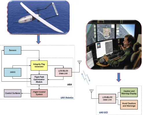
integrity flags (cautions and warnings) in case of predicted/ascertained GNSS data losses or unacceptable signal degradations exceeding the Required Navigation Performance (RNP) specified for each phase of flight, and providing guidance information to the UAS pilot/autopilot to prevent or avoid further data losses/degradations. In this system, the on-board sensors provide information on the aircraft relevant flight parameters (navigation data, engine settings, etc.) to an Integrity Flag Generator (IFG), which is also connected to the GNSS receiver. Using the available data on GNSS and the relevant aircraft flight parameters, integrity signals are generated, which are downlinked to the UAS GCS and used by a Flight Path Optimisation Module (FPOM). Based on the visual and/or aural cautions and warnings generated in the GCS, the UAS pilot can uplinks steering commands through suitable Line-Of-Sight (LOS) or Beyond LOS (BLOS) data links to the on-board avionic system. Alternatively, when the ABIA autonomous mode is activated, optimal manoeuvres are automatically executed by the UA AFCS to avoid GNSS data degradations or losses.
Fig. 1. ABIA system architecture for UAS applications.
The IFG produces caution and warning integrity flags in line with specified times-to-alert [6, 7]. Caution Integrity Flags (CIFs) are predictive annunciations that the GNSS data delivered to the avionics system are going to exceed the RNP thresholds specified for the current and planned flight operational tasks (GNSS alert status). Warning Integrity Flags (WIFs) are reactive annunciations that the GNSS data delivered to the avionics system have exceeded the RNP thresholds specified for the current flight operational task (GNSS fault status). In line with these definitions, the ABIA Time-to-Alert is differentiated in two categories: Time-to-Caution (TTC) and Time-to-Warning (TTW). TTC is the minimum time allowed for the caution flag to be provided to the user before the onset of a GNSS fault resulting in an unsafe condition; TTW is the maximum time allowed from the moment a GNSS fault resulting in an unsafe condition is detected to the moment that the ABIA system provides a warning flag to the user.
III. ABIA INTEGRITYFLAGGENERATION
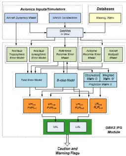
The main causes of GNSS data degradation or signal losses in aviation applications were analysed. Analysing these phenomena and developing suitable mathematical models was essential in order to design the ABIA IFG module [6]. Fig. 2 shows the architecture of the IFG module and input/output data. The ABIA IFG module is designed to provide CIF and WIF alerts in real-time (i.e., in accordance with the specified TTC and TTW requirements in all relevant flight phases). The IFG module inputs are from the GNSS receiver and other UA sensors. The Integrity Flags Layer (IFL) uses a set of predefined CIF/WIF threshold parameters to trigger the generation of both caution and warning flags associated with antenna obscuration, Doppler shift, multipath, carrier-to-noise, interference and satellite geometry degradations [6, 7]. The masking integrity flag criteria are:
When the current A/C manoeuvre will lead to less the 4 satellite in view, the CIF shall be generated.
When only 4 satellites are in view and one (or more) satellite(s) elevation angle is less than 10 degrees, the CIF shall be generated.
When less than 4 satellites are in view, the WIF shall be generated.
[image:2.595.313.551.389.582.2] When only 4 satellites are in view and one (or more) satellite(s) elevation angle is less than 5 degrees, the WIF shall be generated.
Fig. 2. ABIA IFG module architecture.
circle in the horizontal plane, with its centre being at the true position, which describes the region required to contain the indicated horizontal position with a specified probability for a particular navigation mode. Similarly, the Vertical Alert Limit (VAL) is defined as half the length of a segment on the vertical axis, with its centre being at the true position, which describes the region required to contain the indicated vertical position with a specified probability for a particular navigation mode. Hence, the DOP integrity flags criteria are the following:
When the EHE exceeds the HA 95% or the VA 95% alert requirements, the CIF shall be generated.
When the EHE exceeds the HAL or the EVE exceeds the VAL, the WIF shall be generated.
Multipath integrity flags were defined using the Early-Late Phase (ELP) observable and the range error [8]. As described in [7], the multipath integrity flags criteria are the following:
When the Early-Late-Phase (ELP) exceeds 0.1 radians, the caution integrity flag shall be generated.
When the multipath range error exceeds 1 meter, the warning integrity flag shall be generated.
When the multipath ranging error exceeds 2 metres and the aircraft flies in proximity of the ground (below 500 ft AGL), the warning integrity flag shall be generated.
In order to define the integrity thresholds associated with Doppler and fading effects, a dedicated analysis of the GNSS receiver tracking performance was performed. When the GNSS measurement errors exceed certain thresholds, the receiver loses lock to the satellites. Since both the code and carrier tracking loops are nonlinear, especially near the threshold regions, only Monte Carlo simulations of the GNSS receiver in different dynamics and SNR conditions can determine the receiver tracking performance [8, 9]. Numerous sources of measurement errors affect the Phase Lock Loop (PLL), Frequency Lock Loop (FLL) and Delay Lock Loop (DLL). PLL, FLL and DLL are adopted in Scalar Tracking Loops (STL) as well as Vector Tracking Loops (VTL) are considered as part of this research. Error models described in [10] allow determining the effective Carrier-to-Noise (C/N) ratio corresponding to the receiver tracking thresholds. The integrity flag criterion applicable to the ABIA system is:
൬NC
൰୦୰ୣୱ୦୭୪ୢ=
maxቈቀେ ቁ
,ቀ େ
ቁ,ቀ େ
ቁୈ,ቀ େ
ቁ/,ቀ େ
ቁ(1)
where (C/N) is the minimum C/N for PLL tracking, (C/N)is the minimum C/N for FLL tracking,
(C/N)ୈis the minimum C/N for DLL tracking,
(C/N)ାis the minimum C/N for combined PLL and
FLL tracking and (C/N)is the minimumC/N for VTL based tracking. Numerical solution of the above equation shows that the weak link in unaided avionics GNSS receivers is
the carrier tracking loop threshold (greater sensitivity to dynamics stress). Therefore, the (C/N)threshold can be adopted in these cases. Using these theoretical and experimental threshold values, we can also calculate the receiver Jamming-to-Signal (J/S) performance for the various cases of practical interest, as described in [7, 10]. When available, flight test data collected in representative portions of the aircraft operational flight envelope (or the results of Monte Carlo simulation) can be used. Taking an additional 5% margin on the 3-sigma tracking thresholds for the CIF, the following additional criteria are introduced for the ABIA integrity thresholds:
When either 42.25° ≤ 3σ≤ 45°or0.2375T ≤
3σ≤ 0.25Tor0.05d ≤ 3σୈ≤ d,the CIF shall be
generated.
When either 3σ> 45°or 3σ> 1/4ܶor 3σୈ>
݀the WIF shall be generated.
In avionics receivers, lock detectors are used to assess if the satellite signals are being tracked or not tracked. Code lock detection is very similar to estimating the received C/N, inferring that the receiver is operating on or near the correlation peak. The spread spectrum processing gain (G୮) is defined as the ratio of the spread bandwidth to the unspread (baseband) bandwidth and is expressed in dB. The post-correlation Signal-to-Noise(S/N)ratio is calculated from [10]:
(S/N)୮୭ୱ୲ିୡ୭୰୰.= (S/N)୮୰ୣିୡ୭୰୰.+ G୮ (2)
The relationship betweenC/N and jammer signal power (J) is given by [11]:
େ
= [C/N]/ቈ1 + ቀొ బిቁቀెቁ
ୖୡ (3)
whereNis the thermal noise power spectral density,Rcis the P-code chipping rate (chips/s), S is the signal power received at the GNSS antenna input, C is the carrier power and J/S is the jamming-to-signal ratio. The J/S performance of a GNSS receiver at its tracking threshold can be evaluated by the following equation [11]:
ୗ= 10 log QRେቈ1/10 .ଵቀొ బిቁ
ొ − 1/10.ଵቀ ి
ొ బቁ (4)
whereܳ is the processing gain adjustment factor and is equal to 1 for Narrowband Jammers (NBJ), 1.5 for Spread Spectrum Jammers (SSJ) and 2 for Wideband Gaussian Jammers (WGJ), and (C/N) ୍ is the receiver tracking threshold (dB-Hz). When the receiver code is aligned with the transmitted code, the signal power at the band pass output is crushed into approximately 100 Hz of bandwidth. The processing gain of the GNSS receiver is given as:
G= 10 logቀଶେీቁ[dB] (5)
where CRis the chipping rate and Tୈ is the data period. For
that if the value is less than this the satellite signal level is too low to be used in the positioning computations. Therefore, an additional threshold criterion to be accounted for in the ABIA system is given as:
S/N୮୭ୱ୲ିୡ୭୰୰.= S/N୮୰ୣିୡ୭୰୰.+ G୮³10 dB (6)
In line with our discussion, the following additional thresholds are set in the ABIA IFG:
WhenG୮is more than 11 dB (margin of 1 dB), the CIF shall be generated.
When G୮ is less than 9 dB (margin of 1 dB), the WIF shall be generated.
During experimental flight test activities performed with unaided L1 C/A code avionics receivers, it was also found that, in a variety of dynamics conditions, aC/Nof 25 dB-Hz was sufficient to keep tracking of the satellites [7]. Consequently, taking a 2 dB margin for the CIF, the following additional criteria are adopted for S/N integrity flags:
When the signal tracking errors are within 5% of the maximum error budget tolerated by the receiver [12-14], the CIF shall be generated.
When the signal tracking loss conditions occur [13, 14], the WIF shall be generated.
When the C/N is less than 27dB-Hz or the difference between the S/N and the processing gain is less than 12 dB, the CIF shall be generated.
When the C/N is less than 25dB-Hz or the difference between the S/N and the processing gain is less than 10 dB, the WIF shall be generated.
IV. SBAS/GBAS INTEGRITYFLAGGENERATION
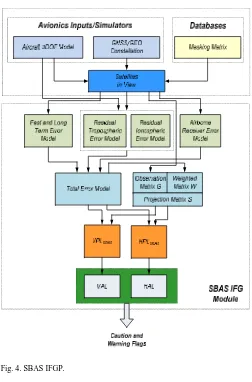
During the landing phase, a GNSS Landing System (GLS) has to be augmented by GBAS in order to achieve the RNP, as well as HPL and VPL requirements. In the case of Local Area Augmentation System (LAAS), the system allows the adoption of multiple Differential Global Positioning System (DGPS) reference receivers. In order to perform a comparative evaluation of the ABIA IFG module with GBAS and SBAS, the GBAS/SBAS Integrity Flag Generation Processes (IFGPs) are considered as illustrated in Fig. 3 and 4 respectively.
VPL and LPL for SBAS and GBAS are calculated in line with the Minimum Operational Performance Standards
(MOPS) for WAAS and LAAS [15, 16]. Additionally, [16] provides the so-called Continuity of Protection Levels in terms of Predicted Lateral and Vertical Protection Levels (PLPL and PVPL). According to the LAAS MOPS, avionics-based functionalities such as ABAS/ABIA would support PLPL/PVPL calculations to generate appropriate caution flags. In our research, we propose that a similar functionality be implemented in SBAS and supported by the ABIA system measurements.
Under these assumptions, the criteria for producing SBAS/GBAS CIFs and WIFs are:
When PVPLGBAS exceeds VAL or PLPLGBAS exceeds
LAL, the CIF shall be generated.
When VPLGBASexceeds VAL or HPLGBASexceeds HAL,
the WIF shall be generated.
When PVPLSBAS exceeds VAL or PLPLSBAS exceeds
LAL, the CIF shall be generated.
When VPLSBASexceeds VAL or HPLSBASexceeds HAL,
[image:4.595.303.558.206.522.2]the WIF shall be generated.
Fig. 3. GBAS IFGP.
As both GBAS and SBAS use redundant GNSS satellite observations to generate integrity flags (i.e., 5 satellites for LAAS and 6 satellites for WAAS), the number of satellites in view can be used to set additional thresholds:
When number of satellites in view is less than 5, the GBAS CIF shall be generated.
When number of satellites in view is less than 4, the GBAS WIF shall be generated.
When number of satellites in view is less than 7, the SBAS CIF shall be generated.
Fig. 4. SBAS IFGP.
V. SENSE-AND-AVOID
Cooperative and non-cooperative SAA are implemented to address UAS safe integration into the non-segregated airspace [17]. The SAA capability can be defined as the automatic detection of possible conflicts (i.e., collision threats) by the UA platform and the implementation of avoidance manoeuvres to prevent the identified collision threats. As part of our research, the possible synergies attainable with the adoption of different detection, tracking and trajectory generation algorithms were studied. The avoidance trajectory is generated considered the use of on-board trajectory re-planning module with dynamically updated constraints based on the intruder and the host dynamics. Additionally, a unified approach to cooperative and non-cooperative SAA is developed by determining the overall uncertainty volume in the airspace surrounding the intruder tracks. The analytical models adopted to compute the overall uncertainty volume in the airspace surrounding an intruder are described in [17]. Based on these mathematical models, the SAA Unified Method (SUM) for cooperative and non-cooperative SAA is developed [17]. In this unified approach, navigation and tracking errors affecting the measurements are considered and translated to unified range and bearing uncertainty descriptors, which apply both to cooperative and non-cooperative scenarios.
VI. ABIA/SAA SYTEMSINTEGRATION
The Position, Velocity and Attitude (PVA) measurements are typically obtained by adopting multi-sensor data fusion techniques [18]. An initial flight path is generated using the aircraft dynamics model. The IFG module run is performed on that trajectory. Based on a Boolean decision logic that sorts sensors data based on estimated performance parameters, the C-SAA or non-cooperative SAA sensors are used for safe separation [17]. If both the safe separation thresholds are violated and a mid-air collision threat is detected the WIF is generated. To prevent any WIF, the flight path optimization process starts when the first CIF is generated. Pseudo-Spectral Optimisation (PSO) and Differential Geometry Optimization (DGO) techniques are used to generate a new optimised trajectory free of any integrity degradations. Depending on the relationship between the available time-to-collision and the computation time PSO and DGO trajectory solutions, the optimised trajectory data are sent to the AFCS (and/or to the ground pilot) for execution of the avoidance manoeuvres. In the trajectory optimisation process time is used as the cost functional and the aircraft dynamics model/satellite elevations are used as path constraints. The implemented decision logic is based on minimisation of the following cost function [19]:
J = w୲∙ tୗ+ wන[SFC ∙ T(t)]dt − wୢ∙ D୫ ୧୬+
−w୧ୢ∙ ∫D(t)dt (7)
where D(t) is the estimated distance of the generated avoidance trajectory points from the avoidance volume associated with the obstacle.D୫ ୧୬ is the min[D(t)] and represents the estimated minimum distance of the avoidance trajectory from the avoidance volume. tୗ= t|ୈ
ౣ is the time at which the safe avoidance condition is successfully attained. SFC [୩
∙ s]is the specific fuel consumption.T(t) is
the thrust profile.w୲, w, wୢ, w୧ୢare the weightings attributed to time, fuel, distance and integral distance respectively. Boundary conditions are set based on the values of the flight parameters when the CIF is generated. An alternate trajectory free of integrity degradation is then generated and sent to the AFCS and/or to the ground pilot.
VII. SIMULATIONCASESTUDIES
Module (MAM) processed the 3DM, TEM, GCS and ADS inputs to determine multipath contributions from the aircraft (wings/fuselage) and from the terrain/objects close to the aircraft. The Obscuration Analysis Module (OAM), and was used to compute the GNSS antenna(e) masking matrixes for all aircraft manoeuvres with inputs from the 3DM, GCS and ADS. The GNSS constellation simulator (GCS) was developed to calculate GNSS satellite position and velocity in the Earth-Centred Earth-Fixed (ECEF) reference frame and to obtain satellite visibility data from any point along the aircraft flight trajectory. The GCS was implemented in MATLABTM and Simulink to simulate GPS and GALILEO constellations. In order to test the ABIA IFG module, a representative UA trajectory was generated for the AEROSONDE UA including the following flight phases:
Climb phase (0-300s);
Turning climb phase (300-600s);
Straight and level (cruise) phase (600-900s);
Level turn phase (900-1200s)
Descending turn phase (1200-1500s);
Final approach phase (1500-1800s);
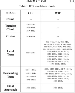
The combined GPS/GALILEO constellation was simulated and the GNSS receiver tracking loops were modelled with a flat random vibration power curve from 20Hz to 2000Hz with amplitude of 0.005gଶ/Hz and the oscillator vibration sensitivity S(f୫) = 1 × 10ିଽ parts/g. All CIFs and WIFs relative to antenna masking, geometric accuracy degradations, SNR, multipath and Doppler shift were generated. The results of this simulation are shown in Table I. In some cases, the CIF was generated but it was not followed by the WIF (this was due to a temporary adverse relative geometry not leading to GNSS signal losses). During the level turn and turning descent phases, the CIF was followed by the WIF. It was also observed that the CIF was always triggered at least 2 seconds before the successive WIF onset (up to 13 seconds in one case during the turning descent phase). These results corroborate the validity of the models developed for the CIF/WIF thresholds. It was also observed that the CIF was always triggered at least 2 seconds before the successive WIF onset. Therefore, it is envisaged that a properly designed ABIA FPM could take full advantage of this predictive behaviour, allowing the UA to correct its flight trajectory/attitude in order to avoid the occurrence of critical GNSS data degradations/losses. Additionally, it is possible that this predictive behaviour be exploited in the pursuit of a GNSS based auto-landing capability.
Assuming that all WIFs are true GNSS outages, we have True Caution Time (TCT), False Caution Time (FCT), True Caution Rate (TCR) and False Caution Rate (FCR) defined as:
TCT = Time of WIF [sec] (8) FCT = Total CIF time[sec] − TCT (9)
TCR =ୋେେ × 100% (10)
[image:6.595.307.558.80.390.2]FCR = 1 − TCR (11)
Table I. IFG simulation results.
PHASE CIF WIF
Climb ---
---Turning Climb
334~374s,
426~446s 517~558s
---Cruise 874~900s
---Level
Turn 901~1200s
903~906s, 913s, 920~924s, 930~931s, 938~942 s, 948~949s, 956~959s, 966~967s, 974~977s, 984~985s, 992~995s, 1002~1003s,
1110~1113s, 1020~1021s, 1028~1031s, 1128~1129s, 1136~1139s, 1146~1147s, 1154~1157s, 1164~1165s, 1172~1175s, 1182~1183s,
1190~1192s, 1200s
Descending Turn
1201~1441s, 1448~1464s,
1471~1487s 1494~1500s
1204s, 1223~1224s, 1247~1249s, 1272~1273s, 1296~1297s, 1320~1321s, 1344~1367s, 1368s,
1391~1392s, 1414~1415s, 1438~1439s, 1461~1462s,
1484~1485s
Final
Approach 1503~1800s 1504~1508s
[image:6.595.309.556.458.681.2]Since SBAS and GBAS are integrated in the IFG, the analysis is performed by flight phase and then a cumulative measure is also obtained. The results are tabulated in Table II.
Table II. IFG simulation results.
PHASE TCT TCR FCR FCT
Climb --- --- ---
---Turning
Climb --- --- --- 104
Cruise --- --- --- 27
Level
Turn 70 18.9% 0.811 300
Descending
Turn 47 14.2% 0.857 282
Final
Approach 5 1.65% 0.983 298
All Flight
Phases 122 10.8% 0.892 1011
B’
B A
C
A
Host Platform ABIA/SAA
Intruder Platform
B C (AEROSONDE UAs) are heading for a collision. Three
different points are shown on the host platform trajectory:
(A) SAA Break-off Point: Corresponding to the point where the host UA initiates the avoidance trajectory (commanded by the SAA system). The cost function criteria adopted in this case is minimum time.
(B) SAA Safe Manoeuvring Point: Corresponding to the point where the host UA can manoeuvre safely (any
manoeuvre within its operational flight envelope) has 0 Risk-Of-Collision (ROC). The SAA cost function criteria switches to minimum time and minimum fuel from this point onwards to get back on the original (desired) track.
[image:7.595.85.497.167.360.2] (C) ABIA Re-join Point: Corresponding to the point where the host UA re-joins the original (desired) track without GNSS data degradations.
Fig. 5. Cooperative SAA scenario (3 UA platforms).
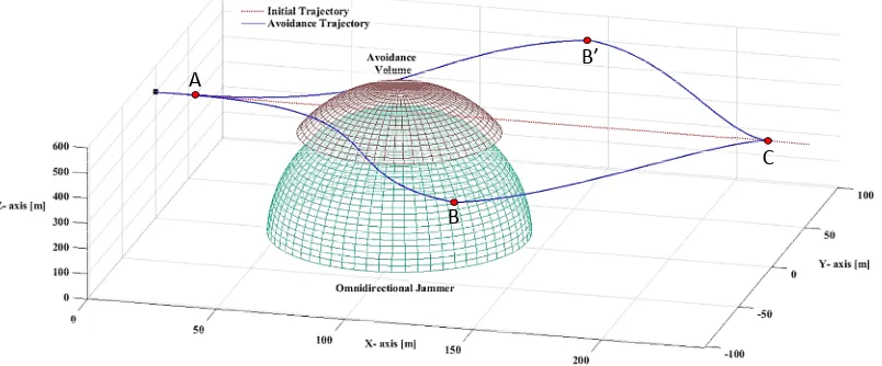
Based on the position uncertainty of the host aircraft an optimised avoidance trajectory without any GNSS data losses is constructed around the overall avoidance volume. In case of jamming, the overall avoidance volume is obtained by combining the tracking error of the jamming signal radiation pattern (main lobe in the case of a directional jammer) and the navigation error of the host platform. The optimised avoidance trajectory is constructed tangential to the radiation pattern of the jammer by taking into account the position uncertainty of the host platform, as described in [10]. A simulation run performed in MATLABTM in the presence of a low-power omnidirectional GNSS personal jammer is shown in Fig. 6.
The jammer is placed at [95, 0, 0] m. The AEROSONDE UA Aircraft Dynamics Model (ADM) was used for this simulation. After the presence of jamming was identified and the jamming source was located, two symmetric optimal avoidance trajectories (ABC and AB’C) were generated based on the cost function approach defined earlier. In this simulation, the constraints imposed by ABIA in terms of RPAS platform dynamics and GNSS satellite elevation angles were considered to generate the optimised avoidance trajectories, thus preventing degradation or losses of navigation data during the whole jammer avoidance manoeuvre.
[image:7.595.96.498.532.699.2]These results confirm that ABIA contributes to providing an Integrity-Augmented SAA (IAS) solution that is well suited for an extension of the current GBAS/SBAS augmentation network in a variety of mission- and safety-critical applications including UAS SAA. The inclusion of ABIA thus provides solid foundations for the development of a future SGAAN architecture meeting the requirements for manned and unmanned aircraft separation maintenance and collision avoidance tasks for all flight phases.
VIII. CONCLUSIONS ANDFUTUREWORK
A comparative evaluation of GNSS Avionics Based Integrity Augmentation (ABIA) with Space-Based and Ground-Based Augmentation Systems (SBAS/GBAS) was presented in this paper. The integration of ABIA in cooperative and non-cooperative SAA architectures leads to an Integrity Augmented SAA (IAS) solution meeting some of the key performance requirements for a safe and unrestricted access of UAS to commercial airspace. Simulation case studies were performed on the ABIA/SAA modules in various representative scenarios, also including the presence of omnidirectional jammers. According to the simulation results, after the integrity caution flag is generated, the time available for the pilot/autopilot to react (before the integrity warning flag is generated), is sufficient for a variety of mission- and safety-critical tasks. The ABIA integration into an existing SAA architecture for cooperative and non-cooperative applications proved that all mid-air collision threats were successfully avoided by implementing suitable trajectory optimisation algorithms. Further research is currently focusing on the following main areas [17-19]:
Extend the ABAS/ABIA concept to other navigation, communication, surveillance and tracking applications.
Investigate ABIA applications and possible evolutions for Next Generation Flight Management System (NG-FMS).
Evaluate the potential of ABAS/ABIA to enhance the performance of next generation Communication, Navigation and Surveillance / Air Traffic Management (CNS/ATM) systems for Performance/Intent Based Operations (PBO/IBO) and Four-Dimensional Trajectory (4DT) management.
Study possible applications of the ABAS/ABIA concepts to advanced mission planning and forensic applications.
REFERENCES
[1] W.M.M Edwards and P.O. Michael, “Validating a concept for airborne sense and avoid”, Proceedings of IEEE American Control Conference (ACC), pp. 1192 – 1197, Portland, Oregon, USA, June 2014. DOI: 10.1109/ACC.2014.6858857
[2] P. Enge, “Local Area Augmentation of GPS for the Precision Approach of Aircraft”, Proceedings of the IEEE, vol. 87, no. 1, January 1999. DOI: 10.1109/5.736345
[3] D. Lawrence, D. Bunce, N.G. Mathur, and C.E. Sigler, “Wide Area Augmentation System (WAAS)-Program Status,” Proceedings of the 20th International Technical Meeting of the Satellite Division of The
Institute of Navigation (ION GNSS 2007), pp. 892-899, Fort Worth, TX, September 2007.
[4] R. Sabatini, T. Moore and C. Hill, “Avionics-Based GNSS Integrity Augmentation for Unmanned Aerial Systems Sense-and-Avoid,” Proceedings of 26th International Technical Meeting of the Satellite Division of the Institute of Navigation: ION GNSS+ 2014, Tampa, Florida, USA, 2014.
[5] R. Sabatini, T. Moore and C. Hill, “Assessing GNSS Integrity Augmentation Techniques in UAV Sense-and-Avoid Architectures,” Sixteenth Australasian Aerospace Congress, Melbourne, Australia, 2015. DOI: 10.13140/2.1.2586.4480
[6] R. Sabatini, T. Moore and C. Hill, “A New Avionics Based GNSS Integrity Augmentation System: Part 1 – Fundamentals,” Journal of Navigation, vol. 66, no. 3, pp. 363-383, May 2013. DOI: 10.1017/S0373463313000027
[7] R. Sabatini, T. Moore and C. Hill, “A New Avionics Based GNSS Integrity Augmentation System: Part 2 – Integrity Flags,” Journal of Navigation, vol. 66, no. 4, pp. 511-522, June 2013. DOI: 10.1017/S0373463313000143
[8] O.M Mubarak and A.G Dempster, “Analysis of Early Late Phase in Single and Dual Frequency GPS Receivers for Multipath Detection,” The University of New South Wales (Australia), 2010. Available at http://www.gmat.unsw.edu.au/snap/staff/omer_mubarak.htm.
[9] P. Ward, “Using a GPS Receiver Monte Carlo Simulator to Predict RF Interference Performance,” Proceedings of 10thInternational Technical Meeting of The Satellite Division of The Institute of Navigation, Kansas City, MO, pp.1473–1482, September 1997.
[10] R. Sabatini, S. Ramasamy, T. Moore and C. Hill, “Avionics-Based GNSS Integrity Augmentation Performance in a Jamming Environment”, Proceedings of the 16th Australian International Aerospace Congress (AIAC16), Melbourne, Australia, February 2015. DOI: 10.13140/2.1.4683.6000
[11] K.M. Kessler, F.G. Karkalik, and J. Sun, “Performance Analysis of Integrated GPS/INS Guidance for Air-to-Ground Weapons in a Jamming Environment”, Proceedings of the Fourth International Technical Meeting of the Satellite Division of The Institute of Navigation, ION GPS, pp. 139-148, September 1991.
[12] P. Ward, “GPS Receiver RF Interference Monitoring, Mitigation, and Analysis Techniques”, NAVIGATION, Journal of the Institute of Navigation, vol. 41, no. 4 (Winter), pp. 367-391, 1994-95.
[13] M.S. Braasch, “On the Characterization of Multipath Errors in Satellite-based Precision Approach and Landing Systems”, College of Engineering and Technology, Ohio University, June 1992.
[14] P. Ward, “Using a GPS Receiver Monte Carlo Simulator to Predict RF Interference Performance”, Proceedings of the 10th International Technical Meeting of The Satellite Division of The Institute of Navigation, Kansas City, USA, pp.1473–1482, September 1997. [15] RTCA, DO-229D - Minimum Operational Performance Standards for
Global Positioning System/Wide Area Augmentation System Airborne Equipment, Washington DC, USA, 2006.
[16] RTCA, DO-245A : Minimum Aviation System Performance Standards for Local Area Augmentation System (LAAS), Washington DC, USA, 2004.
[17] S. Ramasamy, R. Sabatini, and A. Gardi, “Towards a Unified Approach to Cooperative and Non-Cooperative RPAS Detect-and-Avoid”, Proceedings of the Fourth Australasian Unmanned Systems Conference 2014 (ACUS 2014), Melbourne, Australia, 2014. DOI: 10.13140/2.1.4841.3764
[18] F. Cappello, S. Ramasamy, and R. Sabatini, “Multi-Sensor Data Fusion Techniques for RPAS Navigation and Guidance”, Proceedings of the 16thAustralian International Aerospace Congress (AIAC16), Melbourne, Australia, 2015. DOI: 10.13140/2.1.4421.4561