ISSN: 1816-949X
© Medwell Journals, 2019
A New Outer Rotor Permanent Magnet Flux Switching Machine using
Segmental Rotor for Electric Scooter
I. Enwelum Mbadiwe and Erwan Bin Sulaiman
Research Center for Applied Electromagnetics, Universiti Tun Hussein Onn Malaysia,
86400 Parit Raja, Batu Pahat, Johor, Malaysia
Abstract: Electric scooter is a brand of motorcycle using electric motors powered by electricity that is stored in a rechargeable battery. It does not have combustion engine and does not also use fossil fuel for propulsion. The electric motors installed in them improve their performances in terms of energy saving, less heat loss and quick torque response. As a result, they are solution for eliminating high cost of fossil fuel and environmental pollution that contributes to global warming. At the present time, electric motors in electric scooters is a surface mounted Permanent Magnet (PM) motor type 11“ Radial Hub and is not suitable for a distance travel up to 100 km due to location of PMs on the rotating rotor. This study proposes a permanent magnet flux switching motor using segmental rotor in outer rotor configuration with the benefit of direct fabrication to sprocket and robust rotor to contain high speed. The geometric design of this motor is introduced using the parameters of eclimo electric scooter. About 2Dimensional Finite Element Analysis (2D-FEA), JMAG Software released by Japan Research Institute Version 14 is used to investigate four machine performances in terms of flux distribution, cogging torque, induced back-EMF, torque and speed versus power characteristics. Preliminary results showed that 12 slots-14 poles has high torque and high power sustainability for long distance travel.
Key words: Flux switching machine, permanent magnet, electric vehicle, outer segmental rotor,
non-ferromagnetic shaft, sustainability
INTRODUCTION
Alternating Current (AC) machines generate electricity and also enable mechanical work to be done are classified into three kinds namely; Induction Machine (IM), Switched Reluctance Machine (SM) and Synchronous Machine (SM) (Omar et al., 2013; Sulaiman et al., 2012). Furthermore, innovation and refinement of electric motors after the days of Michael Faraday has gone to advanced stage with the invention of Flux Switching Machine (FSM) over half a century ago (Rauch and Johnson, 1955). Flux switching machines have been identified as good candidates for electric scooter and viable means of eliminating high cost of vehicle fuel (Byeong-Mun et al., 2010; Fei et al., 2013).
FSM machines have electrical frequency twice that of synchronous machine are categorized into three namely; Permanent Magnet Flux Switching Machine (PMFSM), Field Wound Flux Switching Machine (WFFSM) and Hybrid Excitation Flux Switching Machine (HEFSM). PMFSM has Permanent Magnet (PM) as its main source of flux. WFFSM has field coil while HEFSM combines both PM and field coil as sources of excitation (Fei et al., 2013; Sulaiman et al., 2013; Jenal et al., 2015).
Another difference between synchronous machine and FSM is in the winding arrangement. FSMs have all active parts located on the stator unlike synchronous machine that has field windings on the rotor. FSMs have passive robust rotors to contain for high speed (Ahmad et al., 2014; Pollock et al., 2003; Zulu, 2010).
FSM with PM excitation has attracted researchers attention due to its various advantages such as free-loss excitation, production of higher torque density, easy cooling of all active parts and favorable for high speed operation (Fei et al., 2009). Furthermore, PMFSM using segmental rotor boost more advantages of saving materials, short end windings, usage of small amount of PM and concentrated windings (Fei et al., 2013 ).
This study presents a new outer rotor Permanent Magnet Flux Switching Machine (PMFSM) using segmental rotor bonded by non-ferromagnetic bonded for electric scooter vehicles. Currently, electric scooter uses the Surface mounted Permanent Magnet Synchronous motor (SPMS) on the rotor. However, mounting Permanent Magnets (PMs) on the rotor makes the motor unsuitable for high speed application and vehicle drive system as performance of machine is reduced due to high copper loss. Besides the high cost of PM, the motor market price is expensive. At present, electric scooters, come in two and three in-wheel with base
torque of 110 Nm and speed of 100 km/h. However, operating at these range levels is less effective and precision as PMFSM achieves quick torque response for wider range of speed (Zhang et al., 2014).
Research on PMFS machine to date has been mainly on salient and toothed rotor structure (Zulu et al., 2012). However, segmental rotor has the advantage of ruggedness, short flux path and at the same time, high torque density with greater efficiency (Chen et al., 2010).
MATERIALS AND METHODS
Operating principle of outer rotor PMFSM: In
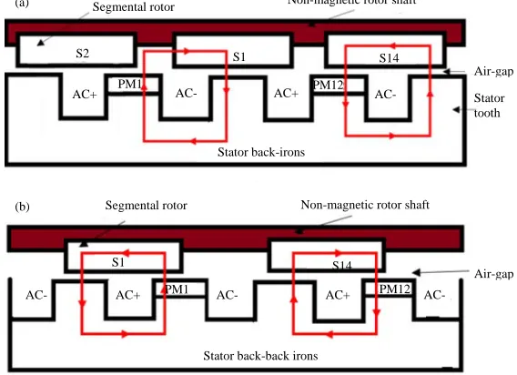
PMFSM, flux is generated by PM. Figure 1 illustrates the operating principle of Outer Segmental Rotor PMFSM (OSR-PMFSM) in which the PMs are positioned at the tip of stator teeth in radial direction with a concentrated armature winding. At initial condition when Stator tooth (S1) is in alignment with rotor R1, there is flux flow from PM1 into R1 in downward direction linking with PM1 and back to the stator back iron because there is flux cancellation in stator S1 by the two PMs different polarities as shown in Fig. 1a. However, in the second alignment when segment rotor S1 begins to rotate in counterclockwise direction, flux begins to flow from PM1 through S1 into the stator pole S1 where previously there was flux cancellation. Therefore, as S1 continues to rotate and at 270° electrical, there is switch of flux at S1 from PM1 to the upward direction as shown in Fig. 1b. While the rotor continues rotating, both the magnitude and polarities of the flux linkage at the stator back core will vary accordingly to complete one cycle.
Segmental rotor machines: Magnetic conducting
segments in rotor configurations have been applied in the 1960’s to conventional machines such as synchronous reluctance machines. The saliency ratio of the synchronous reluctance motor with solid iron rotor segments can be significantly increased with solid rotor topologies compared to using toothed rotors (Fei et al., 2009). Employing segmented rotor provides the advantages of high power and torque densities with PM excitation. The armature stator teeth will experience bipolar flux effectively increasing the magnetic loading capability in the machine structure as the flux undergoes twice the flux. Whilst segmental rotors are applied to enhance a desired machine parameter in the synchronous machine, their use in Switched Reluctance (SR) and FSM involves an alteration to the mechanism of operation including the switching sequences and winding arrangements (Hoang et al., 1997). Only recently, outer rotor FWFSM using segmented rotor was published (Galea et al., 2012). While it has high torque density, it has low efficiency necessary for high speed suitable for long distance travel.
As clearly explained by Mecrow et al. (2003), a segmented rotor topology permits the principle of mutual coupling, the use of alternate tooth windings resulting in high torque densities to be achieved through the utilization of bi-directional flux with the improvement in the slot fill factor, thus, reducing the amount of rotor material used by utilizing shorter end winding.
The objective of this study is to geometrically design a new outer rotor PMFS machine using segmental rotor bonded with non-ferromagnetic shaft as to have high torque and high efficiency for long distance travel.
Fig. 1(a, b): Operating principle of outer segmental rotor PMFSM, (a) First alignment and (b) Second alignment S2
AC+
S1 S14
AC- AC+
AC-PM1 PM12
Air-gap
Stator tooth
Stator back-irons Segmental rotor
Segmental rotor Non-magnetic rotor shaft Non-magnetic rotor shaft
Air-gap S1
AC-
S14
AC+ AC-PM1 AC+ PM12
AC-Stator back-back irons (a)
[image:2.612.157.441.493.699.2]Unlike other types of rotor structures used in electric vehicles for propulsion, only this structure of segmental rotor that has the benefit of direct fabrication to the sprocket for easy coupling to motor tyres. In the same vein, segmental rotor has the ability to provide magnetic path for transmitting the field flux to nearby stator armature coil with respect to rotor position which is a considerable gains due to the reason that it utilizes less rotor conductor material to improve the overall performance of the machine (Kannan, 2012).
RESULTS AND DISCUSSION
Design restrictions and specifications: Table 1 shows the parameters of the new outer rotor PMFSM using segmental rotor bonded by non-ferromagnetic material. While the concept of FSM with toothed rotor has been over half a century ago with single phase and used for airborne application, three phase with 12S-10P configuration was proposed (Ahmad et al., 2014). As interest grew in FSMs, 12S-14P outer rotor HEFSM was proposed (Chao et al., 1996). In the same vein, 6S-7 and 6S-8P on WFFSM and PMFSM with inner toothed and segmental rotors were presented (Ahmad et al., 2012). Furthermore, 6S-8P HEFSM inner rotor was presented (Wu et al., 2007).
Therefore, this new machine employs the above four topologies. The differences between it and the above are namely; outer segmental rotor and three phase. Convention in Eq. 3 is used to find stator to rotor match and will be investigated in order to choose the topology having the best performance.
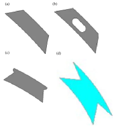
Design of the segmented outer rotor: According to (Galea et al., 2012), three segmental rotor designs were investigated in Fig. 2a-c. However, this new outer segmental rotor PMFSM could not adopt any of them because none presented any proper design justification, thus, design of a new rotor in Fig. 2d and 3. This segmental rotor uses the relationship between rotor segment span angle and rotor tooth width and is
Table1: Machine specifications
Parameters Specifications
No. of phases 3
No. of rotor poles 7, 8, 10, 14
No. of stator poles 6/12
Diameter of machine 279.4 (mm)
Outer rotor shaft radius 139.7 (mm)
Outer rotor radius 137.7 (mm)
Air-gap 0.5 (mm)
Outer stator radius 119.2 (mm)
PM mass 1 (kg)
Armature slot area 467 (mm2
)
Stator shaft radius 30 (mm)
similar to segment of a circle to length of arc and can be given in Eq. 2. Angle of rotor segment span:
(1) 360 rotor tooth width
2 inner outer rotor radius
where, Θ = is the segment span. The outer rotor PMFSM understudy is a doubly salient toothed stator with a
Fig. 2(a-d): Four faces of segmental rotor
Fig. 3 (a-d): Cross section of the designed machines (a)12S-14P, (b) 12S-10P, (c) 6S-8P and (d) 6S-7P
(a) (b)
(c) (d)
Rotor shaft
Rotor
Stator
Armature winding
Armature slot PM
PM
(a) (b)
[image:3.612.331.530.208.431.2] [image:3.612.73.297.605.725.2]Start
Geometery editor
Sketch armature coil Sketch rotor Sketch rotorshaft Sketchstator Sketch PM
Complete model
JMAG designer
Set materials Set condition Add circuit Set mesh and study properties
Simulation
Coil test
No-load analysis
Flux lines and distribution Total flux
Cogging torque
Induced voltage
Result observation
Result observation Load analysis
Torque versus armature current at various current densities
Average maximum torque and power versus speed
End No
No
No
No Yes
Yes
Yes
[image:4.612.164.454.92.534.2]Yes
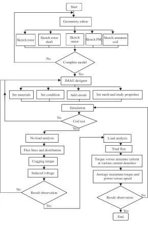
Fig. 4: Design methodology
new geometric segmented rotor topology. Flux switching originates from observation that both the amplitude and polarity in the armature windings change with rotor positions. Each stator pole consists of soft magnetic material and a rectangular Neomax-35AH PM of 1 kg placed alternately on stator pole tooth and embraced by a concentrated armature coil while the rotor pole is made of 35H210 sheet steel. The stator pole tooth width and rotor pole tooth width follow the general convention in Eq. 2. The stator pole number Ns and rotor pole number Nr for
the three phase configuration are determined using Eq. 3: (2) Stator tooth width = Rotor tooth width
(3)
r s
m
N N 1±
2q
Where:
Nr : The number of rotor pole Ns : The number of stator poles
m : An integer q : Number of phase
Fig. 5(a, b): Flux lines and flux distribution
conditions, circuit configuration and properties. In this study, the following parameters are specified; diameter of machine is 297.4 mm, slot area is 467 mm2, number of
conductors 5 turns and input DC current is 275Arms, input
three-phase Voltage 60 V and speed of 1900 rpm. Slot filling factor is calculated using Eq. 4:
(4)
a a rms
a
JαS I
N
Where:
Ja : The current density in (A/mm 2)
Sa : The slot area of the armature coil α : Winding filling factor of 0.5 Na : The number of turns
Flux lines and flux distribution: At no load condition, flux distribution is observed for the four machines by injecting the maximum current density of Ja 30 A/mm
2
at zero rotor position as shown in Fig. 5. Between the two stator poles, there is more flux distribution in 12 stators than in 5 stators. For 6S-7P, flux is distributed evenly in the rotor than in the stator poles due to near number of rotor pole as shown in Fig. 5b. In 6S-8P flux is even in the rotor and empty space in the stator due to leakage as shown in Fig. 5a. Furthermore, 12S-10P and 12S-14P exhibited satisfactory flux distribution and linkage with flux more concentrated in 12S-14P than 12S-10P as marked in Fig. 5b.
[image:5.612.159.294.92.271.2]FEA based performances analysis: The designs are examined using the commercial 2D-FEA package released by JMAG Version 14. The machines are analyzed at no-load and load conditions, respectively. At no-load, the coil arrangement test were evaluated by arranging each armature coil phase to verify properly the
Fig. 6: Flux linkage of U-phase of machines
operating principle of the machine. The strength of flux, flux lines and flux distribution, induced voltage, the cogging torque, phase back-EMF and average torque are all investigated.
Figure 6 illustrates flux linkage waveform of U-phase of the machines. A cursory look shows that 12S-14P has high magnetic flux of 12 mWb while 12S-10P has 16 mWb. 6S-7P achieves 10 mWb and 6S-8P with lowest magnetic flux value.
Cogging torque: At no-load condition, the cogging torque of the five machines configurations are examined at zero rotor position by setting current density of Ja = 0 A/mm2. Figure 7 shows the cogging torque
investigation of the machines: It is observed that 12S-14P operating at the electrical 25.7° of rotor rotation pulsated to 5 Nm peak, 12S-10P with 36 electrical degrees 6 Nm peak, 6S-7P and 6S-8P rotating with 45° electrical recording 60 Nm and producing three (a) (b)
6S-7P 6S-8P 6S-7P
12S-10P 12S-14P
6S-7P
12S-10P 12S-14P
0.020
0.015
0.010
0.005
0
-0.005
-0.010
-0.015
-0.020
Mag
n
etic f
lux (W
b)
Electric cycle (°) 12S-10P 12S-14P
[image:5.612.207.516.93.458.2]electrical cycles which is not safe for machine operation. For 12S-7P, though rotating at 51.4 electrical degrees achieves 10 Nm has odd number of rotor pole creates an unbalanced field distribution in the air-gap making the machine to have an unbalance magnetic-pull during motor operation (Kannan, 2012; Ahmad et al., 2013; Chao et al., 1996). Therefore, 12S-14P with the lowest electrical cycle producing 6 cycles of smooth waveform with the lowest cogging torque is considered the best and can be further reduced at the stage of optimization.
[image:6.612.90.279.309.435.2]Induced back-EMF: The induced back-EMF of the four machines at the speed of 1900 rpm and conducted under maximum current density is illustrated in Fig. 8. A cursory look at each of the machines waveform shows that 6S-7P possesses ripples and much harmonics, 6S-8P
Fig. 7: Cogging torque comparison between the machines
has degraded sinusoidal waveform while 12S-10P has bad harmonics. However, the waveform of 12S-14P is very favorable. Therefore with this sinusoidal waveform delivered by 12S-14P, gives it an advantage to perform better still and also provide protection in case of uncertain system fault.
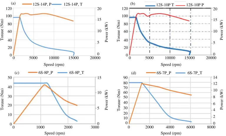
[image:6.612.329.519.313.430.2]Average torque, speed and power: Figure 9 illustrates the characteristics of torque and speed versus power of the four machines under the maximum current density. Figure 9a shows machine 12S-14P which at the base speed of 3000 rpm, yields torque of 96.12 Nm with power output of 16 kW. Figure 9b is 12S-10P with the torque of 89.07 Nm and produces lower power. Figure 9c which is 6S-8P machine, achieves a favorable power output has high cogging torque and worst distorted back-EMF waveform. Lastly, Fig. 9d is 6S-7P has odd pole structure
Fig. 8: Back-EMF of the machines at 1900 rpm
Fig. 9(a-d): Torque and power versus speed characteristics of the machines 100
0
-100
Electric cycle (°)
To
rqu
e (N
m)
12S-10P 12S-14P 6S-8P 6S-7P
100
0
-100
Electric cycle (°)
To
rqu
e (N
m)
12S-10P 12S-14P 6S-7P 6S-8P (F) B-EMF 120 100 80 60 40 20 0 50 40 30 20 10 0 90 80 70 60 50 40 30 20 10 0 120 100 80 60 40 20 0 20 15 10 5 0 20 15 10 5 0 15 10 5 0 14 12 10 8 6 4 2 0 To rq ue (Nm ) To rq ue (Nm ) To rq ue (Nm ) To rq ue (Nm ) Power (kW ) Power (kW ) Power (kW ) Power (kW )
0 5000 10000 15000 20000 0 5000 10000 15000 20000
0 2000 4000 6000 8000 0 1000 2000 3000
Speed (rpm) Speed (rpm)
Speed (rpm) Speed (rpm)
12S-14P, P 12S-14P, T
6S-8P_P 6S-8P_T 6S-7P_P 6S-7P_T 12S-10P T 12S-10P P
(a) (b)
[image:6.612.112.496.469.701.2]which creates an unbalanced field distribution in the air gap making the machine to have an unbalance magnetic-pull during motor operation.
CONCLUSION
In this study, four topologies of the proposed PMFSM have been designed and investigated for high torque and high power necessary for long distance travel. The initial output performances such as flux capability, cogging torque, induced voltage, output torque and power have been examined and compared. The 12S-14P structure achieved more favourable three phase sinuoidal waveform, high flux magnitude as well as highest torque and output power. Therefore, it has secured the best candidate for optimization and further analysis for reliable and sustenable electric scooter application.
ACKNOWLEDGEMENT
“This research was partly sponsored by the Center for Graduate Studies (CGS), UTHM”.
REFERENCES
Ahmad, M.Z., E. Sulaiman, F. Khan and Z.A. Haron, 2014. Electromagnetic flux analysis on a new outer-rotor hybrid excitation flux switching machine. Proceedings of the 2014 IEEE Asia-Pacific Conference on Applied Electromagnetics (APACE), December 8-10, 2014, IEEE, Johor, Malaysia, ISBN:978-1-4799-6604-2, pp: 175-178.
Ahmad, M.Z., E. Sulaiman, Z.A. Haron and T. Kosaka, 2012. Preliminary studies on a new outer-rotor permanent magnet flux switching machine with hybrid excitation flux for direct drive EV applications. Proceedings of the 2012 IEEE International Conference on Power and Energy (PECon), December 2-5, 2012, IEEE, Parit Raja, Malaysia, ISBN:978-1-4673-5017-4, pp: 928-933. Chao, B., Z.J. Liu and T.S. Low, 1996. Analysis of
unbalanced-magnetic-pulls in hard disk drive spindle motors using a hybrid method. IEEE. Trans. Magn., 32: 4308-4310.
Fei, W., P.C.K. Luk, B. Xia and D. Wu, 2013. Design improvement of outer-rotor permanent magnet flux switching machine for direct-drive urban electric vehicle propulsion. Proceedings of the 39th Annual Conference of the IEEE Industrial Electronics Society (IECON) 2013, November 10-13, 2013, IEEE, Cranfield, England, ISBN:978-1-4799-0225-5, pp: 7319-7324.
Fei, W., P.C.K. Luk, J. Shen and Y. Wang, 2009. A novel outer-rotor permanent-magnet flux-switching machine for urban electric vehicle propulsion. Proceedings of the 3rd International Conference on Power Electronics Systems and Applications (PESA) 2009, May 20-22, 2009, IEEE, Shrivenham, England, ISBN:978-1-4244-3845-7, pp: 1-6.
Galea, M., C. Gerada and T. Hamiti, 2012. Design considerations for an outer rotor, field wound, flux switching machine. Proceedings of the 20th International Conference on Electrical Machines (ICEM) 2012, September 2-5, 2012, IEEE, Nottingham, England, ISBN:978-1-4673-0143-5, pp: 171-176.
Jenal, M., E. Sulaiman, F. Khan and M. Ahmad, 2015. 2D-FEA based design study of salient rotor three-phase permanent magnet flux switching machine with concentrated winding. Appl. Mech. Mater., 785: 274-279.
Mecrow, B.C., E.A. El-Kharashi, J.W. Finch and A.G. Jack, 2003. Segmental rotor switched reluctance motors with single-tooth windings. IEE. Proc. Electr. Power Appl., 150: 591-599.
Pollock, C., H. Pollock and M. Brackley, 2003. Electronically controlled flux switching motors: A comparison with an induction motor driving an axial fan. Proceedings of the 29th Annual Conference on the IEEE Industrial Electronics Society (IECON 03), Vol. 3, November 2-6, 2003, IEEE, Leicester, England, ISBN:0-7803-7906-3, pp: 2465-2470. Rauch, S.E. and L.J. Johnson, 1955. Design principles of
flux-switch alternators: Transactions of the american institute of electrical engineers. Part III Power Apparatus Syst., 74: 1261-1268.
Sulaiman, E., F. Khan, M.Z. Ahmad, M. Jenal and S.A. Zulkifli et al., 2013. Investigation of field excitation switched flux motor with segmental rotor. Proceedings of the 2013 IEEE Conference on Clean Energy and Technology (CEAT), November 18-20, 2013, IEEE, Parit Raja, Malaysia, ISBN:978-1-4799-3239-9, pp: 317-322.
Sulaiman, E.B., T. Kosaka and N. Matsui, 2012. Design study and experimental analysis of wound field flux switching motor for HEV applications. Proceedings of the 20th International Conference on Electrical Machines (ICEM) 2012, September 2-5, 2012, IEEE, Johor, Malaysia, ISBN:978-1-4673-0143-5, pp: 1269-1275.
Zhang, H., D.H. Lee, C.W. Lee and J.W. Ahn, 2014. Design and analysis of a segmental rotor type 12/8 switched reluctance motor. J. Power Electron., 14: 866-873.
Zulu, A., 2010. Flux switching machines using segmental rotors. Ph.D Thesis, University of Newcastle, Callaghan, New South Wales.