warwick.ac.uk/lib-publications
Original citation:
Rochford, L. A. (Luke A.), Ramadan, A. J., Holliday, S., Jones, T. S. (Tim S.) and Nielsen, C. B..
(2016) The effect of fluorination on the surface structure of truxenones. RSC Advances , 6
(71). pp. 67315-67318.
Permanent WRAP URL:
http://wrap.warwick.ac.uk/86174
Copyright and reuse:
The Warwick Research Archive Portal (WRAP) makes this work of researchers of the
University of Warwick available open access under the following conditions.
This article is made available under the Creative Commons Attribution 4.0 International
license (CC BY 4.0) and may be reused according to the conditions of the license. For more
details see:
http://creativecommons.org/licenses/by/4.0/
A note on versions:
The version presented in WRAP is the published version, or, version of record, and may be
cited as it appears here.
The e
ff
ect of
fl
uorination on the surface structure
of truxenones
†
L. A. Rochford,*aA. J. Ramadan,bS. Holliday,cT. S. Jonesaand C. B. Nielsencd
The surface structure of partiallyfluorinated truxenone (F3-truxenone) molecules on Cu (111) has been probed using a combination of scanning tunneling microscopy (STM) and low energy electron diffraction (LEED). Codeposition of F3-truxenone and the parent truxenone molecule leads to a mix of discrete F3 -truxenone and -truxenone islands on a Cu (111) surface. Due to the differences in rotational orientation of each type of molecular island proved by LEED the otherwise indistiguishable molecules can be identified in STM images.
Introduction
At its most fundamental, theeld of organic electronics relies on interfaces between organic molecules and solid surfaces.1–3 Devices such as organic photovoltaics commonly incorporate at least one interface between an organic molecule and a metal or metal oxide.4,5As well as control of device performance through interface modication, organic chemistry is widely used to design and modify molecules with device applications in mind.6 Production of electron acceptor materials for the replacement of archetypal acceptors (such as C60) is the subject of huge contemporary research activity.7Axial substitution of hydrogen for halogen atoms in conjugated small molecules is a widely used method to control their electronic properties.8–10 For example in planar phthalocyanine molecules axialuorination has been shown to rigidly shi energy levels to lower values while preserving the symmetry of the molecule.11This shiis of sufficient size to allowuorinated adducts of the phthalocya-nines to accept electrons from electron donating molecules.12 While measurements of the effect of this modication upon relevant molecular energy levels (LUMO/HOMO) are widely undertaken, far less attention has been paid to changes induced in crystal structure–both in single crystals and at interfaces.13,14 Forming ordered structures comprised of small conjugated organic molecules on the surface of inorganic crystals is a well-established method of probing their structure and properties.15 Here, we study the effect of partial axial
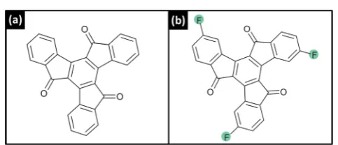
uorination of truxenone (diindeno[1,2-a; 10,20-c] uorene-5,10,15-trione) (Fig. 1) on surface structure in molecular monolayers. Truxenones have shown particular recent efficacy for use as electron acceptors in organic electronic devices and derivatives have been used to produce highly efficient organic photovoltaic devices.16–18The use of high resolution scanning tunnelling microscopy (STM) and low energy electron diff rac-tion (LEED) allows the surface structures of truxenone and F3 -truxenone to be compared.
Experimental
Truxenone and F3-truxenone were synthesised following litera-ture procedures19,20 and triply puried by thermal gradient sublimation before degassing 20 C below the evaporation temperature for several days.21 NMR data and full synthesis details are presented in the ESI (S1 and S2).†A single crystal Cu (111) substrate (Surface Preparation Lab, NL–cutting accuracy 0.1) was prepared in vacuum by repeated cycles of argon ion sputtering and annealing (Ar+energy 1.5 keV temperature 550
C). Standard low-temperature effusion cells (Karl Eberl) were
used at 150 C (truxenone) and 155 C (F3-truxenone) for molecular growth. Truxenone and F3-truxenone layers were produced by evaporation onto a clean Cu (111) surface, initially
Fig. 1 Chemical structures of (a) truxenone and (b) F3-truxenone.
a
Department of Chemistry, University of Warwick, Gibbet Hill Road, Coventry, CV4 7AL, UK. E-mail: [email protected]
bDepartment of Physics, Clarendon Laboratory, University of Oxford, Oxford OX1 3PU, UK
cDepartment of Chemistry, Imperial College London, South Kensington, SW7 2AZ, UK
dMaterials Research Institute and School of Biological and Chemical Sciences, Queen Mary University of London, Mile End Road, London E1 4NS, UK
†Electronic supplementary information (ESI) available: Additional STM images and 2D-FFTs. See DOI: 10.1039/c6ra14158g
Cite this:RSC Adv., 2016,6, 67315
Received 31st May 2016 Accepted 8th July 2016 DOI: 10.1039/c6ra14158g
www.rsc.org/advances
PAPER
Open Access Article. Published on 08 July 2016. Downloaded on 27/02/2017 09:56:50.
This article is licensed under a
Creative Commons Attribution 3.0 Unported Licence.
View Article Online
[image:2.595.307.549.606.710.2]monitored using post growth LEED with increasing deposition time. All characterisation was carried out at ambient tempera-ture in a custom-built multi-chamber ultra-high vacuum (UHV) system with a base pressure better than 31010mbar. STM images were recorded with an STM/AFM (Omicron) operated in constant current mode using electrochemically etched poly-crystalline tungsten tips. Applied voltages and tunnelling currents are indicated ingure captions. Images and 2D-FFTs were produced using the open source soware Gwyddion®. LEED patterns were collected with a SPECTALEED (Omicron) rear-view MCP-LEED with nano-amp primary beam current. Images of these diffraction patterns were captured using a digital CCD camera interfaced to a personal computer, and are presented with their colours inverted for clarity. Simulated patterns and surface meshes were calculated using the open source soware LEEDpat4.1.
Results and discussion
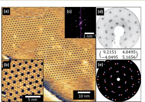
In order to compare the behaviour of the parent truxenone and the uorinated derivative (4,9,14-triuorotruxenone, F3 -trux-enone) thin lms were grown by evaporation in ultra-high vacuum. As truxenone has recently been shown to grow commensurate epitaxial structures on Cu (111) surfaces this surface was selected for growth of both molecules.22Growth was undertaken in short increments (one minute) until sharp LEED patterns (Fig. 2(d)) were observed (ten minutes in total). The overlayer did not form the same commensurate p(8x8) structure as the parent truxenone, and consisted of twice the number of rst order diffraction spots. This is suggestive of rotational domains induced by misalignment of the molecular overlayer mesh with one of the high symmetry directions of the substrate.23
STM images were collected from the surface and are pre-sented in Fig. 2(a) and (b). Large domains of F3-truxenone were
present on the surface and the molecular visualisation was similar to that observed previously for truxenone. Each F3 -truxenone molecule appeared as a three-lobed triangular feature with a less bright central region rather than the single bright triangular shape as previously observed for trux-enone.24,25 This additional contouring in the local density of states (LDOS) of the molecule may be due to theuorine atoms creating an uneven distribution of electron density in the outermost phenyl rings with respect to the core.26,27Whether this effect is an electronic or local structural effect is problem-atic to discern with STM measurements. The authors note, however, that we cannot rule out small changes in tip condition being responsible for the change in contrast. The porous honeycomb structure observed was misaligned with the substrate primitive by 26(0.5) according to LEED and STM data (Fig. 2). Some of the ‘pores’ of the honeycomb network appear to belled and appear with similarly bright contrast to the surrounding molecules in STM images. The identity of these species is unclear but they may be collections of copper ad-atoms (mobile at room temperature), or small impurities around which the layer may have crystallised.
The size of the rhombic molecular unit cell (a¼120) was the same (r1 ¼r2 ¼ 2.07 nm) as previously observed in trux-enone (within the experimental error) on Cu (111). However, these dimensions coupled with the misalignment with respect to the substrate suggest incommensurate ordering of the F3 -truxenone layer. Unlike the unsubstituted -truxenone p(8x8) and p(5x5) cases, the translational symmetry of the surface is not preserved as the principle lattice vectors of the overlayer and substrate do not align. With the measured angles and unit cell dimensions the following transfer matrix could be constructed:
9:2151 4:0495 4:0495 5:1656
The two dimensional fast Fourier transform (2D-FFT) of the large scale STM image shown in Fig. 2(a) is inset as Fig. 2(c). This shows a single hexagonal pattern, corresponding to one of the mirror domains created by misalignment with a substrate prim-itive lattice vector. Additional images (see ESI, Fig. S3†) capture regions in which both (symmetry related) orientations are present, and their 2D-FFT reects the symmetry of the LEED pattern'srst order spots. Simulations using the transfer matrix presented are shown in Fig. 2(e) and consider both of these symmetry related domains. The close resemblance of the simulated and experi-mental LEED pattern conrms that our suggested surface mesh accurately describes the F3-truxenone layer on Cu (111).
Although only a proportion (1/4) of the axial hydrogen atoms are replaced withuorine the precursor used in the synthesis ensures that only a single diastereomer is formed.28The surface immobilisation will, as in the case of unsubstituted truxenone, form two enantiomers of the F3-truxenone. Our STM images do not allow discrimination between the enantiomers as single atoms cannot be resolved and no‘handedness’is obvious in the molecular footprint.29Commensurate truxenone structures on Cu (111) can accommodate both enantiomers, and this may also be true with incommensurate structures of F3-truxenone
Fig. 2 STM images of F3-truxenone/Cu (111) at (a) low (VS¼ 2 V,IT¼ 65 pA) and (b) high (VS¼ 2 V,IT¼65 pA) magnification along with (c) 2D-FFT of the low magnification image. Panel (d) shows a LEED pattern of the surface at 12 eV along with the assigned surface mesh matrix and (e) a simulated pattern (each domain is separately coloured).
RSC Advances Paper
Open Access Article. Published on 08 July 2016. Downloaded on 27/02/2017 09:56:50.
This article is licensed under a
Creative Commons Attribution 3.0 Unported Licence.
[image:3.595.48.291.490.660.2]seen here. Although LEED patterns show two domains, the underlying cause of the misalignment with the substrate is unclear. In one case, enantiopure domains may be forming with one enantiomer responsible for each of the domains.30 However, the packing arrangement of the molecules may not be selective to one or the other surface enantiomer and enantio-morphous domains may be present.31,32 In this case the misalignment of the F3-truxenone with the substrate would be intrinsic to the replacement of the hydrogen atoms with uo-rine. Unfortunately this is beyond the capabilities of our combined STM and LEED measurements, even the absolute point group symmetry of the molecular overlayer cannot be unambiguously determined.
The precise adsorption conguration site and the orienta-tion of the molecule with respect to the surface could only be directly measured with synchrotron based techniques. Normal incidence X-ray standing wave (NIXSW), and photoelectron diffraction (PhD) would provide some insight into this but these data are not available at present for this system.33,34Despite these caveats, the surface mesh extracted from LEED and STM remains valid although without a unique solution.
For direct comparison the parent truxenone molecule was evaporated to a similar coverage on Cu (111) and character-isation of this interface is shown in Fig. 3. As previously re-ported, a porous network was formed with a rhombic unit cell aligned to dene a p(8x8) surface mesh.
LEED patterns reect this ordering and symmetry, and no mirror-plane related domains are observed due to the align-ment of the organic overlayer and substrate primitive lattice vectors.
Inspection of STM images of single-component (truxenone or F3-truxenone)lms highlights the striking similarity between the appearances of individual molecules. Attempts at bias-dependent imaging to discern differences in molecular orbital derived states were unsuccessful due to the instability of the tip and/or surface at room temperature. In order to compare the observations in STM and crystallography of both molecules
simultaneously they were co-evaporated onto Cu (111) from separate evaporation sources. As theux was being effectively doubled compared to growth of single-component lms, the growth time was halved.
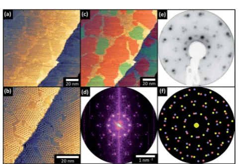
Mixed truxenone and F3-truxenone lms exhibited LEED patterns which could be understood as a superposition of the individual patterns of each component (Fig. 4). This was strongly suggestive of the formation of discrete domains of each molecule without ‘mixtures’ of the two molecules forming, although small amounts of local co-crystallisation cannot be completely ruled out. We can be sure that no ordered regions greater in size than the LEED transfer width (approx. 50 nm) with structures different to those previously discussed are present. It could be reasonably expected that intermixing molecules which differed only by their axialuorination would lead to a modication to the unit cell or orientation observed.35 Co-depositedlms were also analysed by STM and exhibit familiar open honeycomb structures as observed individually for truxenone and F3-truxenone. On close inspection the rota-tional orientation of individual islands (assuming that poorly-dened regions are bare Cu substrate) is not the same across the imaged region. This can be clearly demonstrated by taking the 2D-FFT of the STM image, which produced a remarkably close approximation of the LEED pattern from this surface.
STM images can therefore be inspected and otherwise indistinguishable molecules can be identied by their in-plane rotational orientation. To show the local orientation (and therefore the composition of each island), the large-scale STM image in Fig. 4 has been overlaid with false coloured tiles to indicated areas in which F3-truxenone and truxenone have separately crystallised. Lateral heterojunctions of two dimen-sional inorganic materials (such as graphene and hexagonal boron nitride) have attracted signicant recent interest for electronic device applications.36 The results presented here
Fig. 3 STM images of truxenone/Cu (111) at (a) low (VS¼ 1.25 V,IT¼ 100 pA) and (b) high (VS¼ 1.25 V,IT¼100 pA) magnification along with (c) 2D-FFT of the low magnification image. Panel (d) shows a LEED pattern of the surface at 12 eV along with the assigned surface mesh matrix and (e) a simulated pattern.
Fig. 4 STM images of co-deposited F3-truxenone and truxenone on Cu (111) at (a) low (VS¼ 1.30 V,IT¼85 pA) and (b) high (VS¼ 1.5 V,IT
¼ 75 pA) magnification. A false cover overlay is added to the low magnification image in panel (c) to mark domains of F3-truxenone (green) and truxenone (red). The 2D-FFT of the low-resolution image is shown in (d) along with (e) the LEED pattern at 12 eV and (f) the combined simulated pattern (yellow¼truxenone, blue + red¼F3 -truxenone).
Open Access Article. Published on 08 July 2016. Downloaded on 27/02/2017 09:56:50.
This article is licensed under a
[image:4.595.308.550.475.640.2] [image:4.595.49.288.504.671.2]demonstrate that with somene tuning, organic lateral heter-ojunctions could be realised.
Conclusions
The surface structure of truxenone and partially uorinated truxenone on a Cu (111) surface are characterised by STM and LEED. When the molecules are co-evaporated they separately crystallise into discrete islands, and despite very similar appearances in STM images when present individually on Cu (111) the orientation of grains with respect to the substrate allows molecular identity to be discerned. The spontaneous organisation of each molecule into discrete islands demon-strates that axial halogen substitution (intended for electronic modication) can produce concomitant surface structure changes. Further tuning of the molecular structure through synthetic chemistry may allow the degree of separation to be controlled and intermixed phases to be observed. If further control can be demonstrated, the fabrication of lateral molecular heterojunctions could be realised with these molecular systems.
Acknowledgements
LAR, AJR and TSJ acknowledge support from the Engineering and Physical Sciences Research Council [Grant Number EP/ H021388/1]. SH and CBN acknowledge support from the following funding bodies: EPSRC Project EP/G037515/1, EC FP7 Project SC2 (610115), EC FP7 Project ArtESun (604397), and EC FP7 POLYMED (612538). The raw data associated with this article can be accessed at the following DOI: 10.17632/ mmp65j8jgs.2
Notes and references
1 S. R. Forrest,Chem. Rev., 1997,97, 1793–1896. 2 S. R. Forrest,Nature, 2004,428, 911–918. 3 N. Koch,ChemPhysChem, 2007,8, 1438–1455.
4 M. T. Greiner, M. G. Helander, W.-M. Tang, Z.-B. Wang, J. Qiu and Z.-H. Lu,Nat. Mater., 2011,11, 76–81.
5 A. Kahn and N. Koch, inThe Molecule-Metal Interface, Wiley-VCH Verlag GmbH & Co. KGaA, Weinheim, Germany, 2013, pp. 219–241.
6 J. E. Anthony,Chem. Rev., 2006,106, 5028–5048.
7 C. B. Nielsen, S. Holliday, H.-Y. Chen, S. J. Cryer and I. McCulloch,Acc. Chem. Res., 2015,48, 2803–2812.
8 K. Cnops, G. Zango, J. Genoe, P. Heremans, M. V. Martinez-Diaz, T. Torres and D. Cheyns,J. Am. Chem. Soc., 2015,137, 8991–8997.
9 P. Sullivan, A. Duraud, L. Hancox, N. Beaumont, G. Mirri, J. H. R. Tucker, R. A. Hatton, M. Shipman and T. S. Jones,
Adv. Energy Mater., 2011,1, 352–355.
10 C. B. Nielsen, A. J. P. White and I. McCulloch,J. Org. Chem., 2015,80, 5045–5048.
11 W. Wu, L. A. Rochford, S. Felton, Z. Wu, J. L. Yang, S. Heutz, G. Aeppli, T. S. Jones, N. M. Harrison and A. J. Fisher,J. Appl. Phys., 2013,113, 013914.
12 J. L. Yang, S. Schumann, R. A. Hatton and T. S. Jones,Org. Electron., 2010,11, 1399–1402.
13 H. Jiang, J. Ye, P. Hu, F. Wei, K. Du, N. Wang, T. Ba, S. Feng and C. Kloc,Sci. Rep., 2014,4, 7573.
14 J. Endres, I. Pelczer, B. P. Rand and A. Kahn,Chem. Mater., 2016,28, 794–801.
15 J. M. Gottfried,Surf. Sci. Rep., 2015,70, 259–379.
16 C. B. Nielsen, E. Voroshazi, S. Holliday, K. Cnops, B. P. Rand and I. McCulloch,J. Mater. Chem. A, 2013,1, 73–76. 17 C. B. Nielsen, E. Voroshazi, S. Holliday, K. Cnops, D. Cheyns
and I. McCulloch,J. Mater. Chem. A, 2014,2, 12348–12354. 18 G. Zhang, V. Lami, F. Rominger, Y. Vaynzof and
M. Mastalerz, Angew. Chem., Int. Ed., 2016, 55(12), 3977– 3981.
19 E. V. Dehmlow and T. Kelle,Synth. Commun., 1997,27, 2021– 2031.
20 L. Sanguinet, J. C. Williams, Z. Yang, R. J. Twieg, G. Mao, K. D. Singer, G. Wiggers and R. G. Petschek,Chem. Mater., 2006,18, 4259–4269.
21 A. R. McGhie, A. F. Garito and A. J. Heeger,J. Cryst. Growth, 1974,22, 295–297.
22 A. J. Ramadan, C. B. Nielsen, S. Holliday, T. S. Jones, I. McCulloch and L. A. Rochford,RSC Adv., 2016,6, 17125– 17128.
23 L. A. Rochford, I. Hancox and T. S. Jones,Surf. Sci., 2014,628, 62–65.
24 Z.-Y. Yang, Y. Tao, T. Chen, H.-J. Yan and Z.-X. Wang,Phys. Chem. Chem. Phys., 2013,15, 2105.
25 F. Chen, Z. Hu, Y. Ji, A. Zhao, B. Wang, J. Yang and J. G. Hou,
Phys. Chem. Chem. Phys., 2012,14, 3980.
26 D. G. de Oteyza, A. El-Sayed, J. M. Garcia-Lastra, E. Goiri, T. N. Krauss, A. Turak, E. Barrena, H. Dosch, J. Zegenhagen, A. Rubio, Y. Wakayama and J. E. Ortega,J. Chem. Phys., 2010,133, 214703.
27 H. Huang, W. Chen and A. T. S. Wee,J. Phys. Chem. C, 2008,
112, 14913–14918.
28 C. Lambert, G. N¨oll, E. Schm¨alzlin, K. Meerholz and C. Br¨auchle,Chem.–Eur. J., 1998,4, 2129–2135.
29 W. Xiao, X. Feng, P. Ruffieux, O. Gr¨oning, K. M¨ullen and R. Fasel,J. Am. Chem. Soc., 2008,130, 8910–8912.
30 C. B. France and B. A. Parkinson,J. Am. Chem. Soc., 2003,
125, 12712–12713.
31 R. Fasel, M. Parschau and K.-H. Ernst, Nature, 2006,439, 449–452.
32 F. Stevens, D. J. Dyer and D. M. Walba,Angew. Chem., Int. Ed. Engl., 1996,35, 900–901.
33 D. Woodruff,Surf. Sci. Rep., 2007,62, 1–38. 34 D. P. Woodruff,Prog. Surf. Sci., 1998,57, 1–60.
35 Y. L. Huang, W. Chen and A. T. S. Wee,J. Am. Chem. Soc., 2011,133, 820–825.
36 M. P. Levendorf, C.-J. Kim, L. Brown, P. Y. Huang, R. W. Havener, D. A. Muller and J. Park,Nature, 2012,488, 627–632.
RSC Advances Paper
Open Access Article. Published on 08 July 2016. Downloaded on 27/02/2017 09:56:50.
This article is licensed under a
Creative Commons Attribution 3.0 Unported Licence.