ISSN Online: 2327-4379 ISSN Print: 2327-4352
Numerical Study of Mechanisms of the Vortex
Formation in the Wake of Dual-Flapping Foils
Xingjian Lin
1, Guoyi He
1, Xinyi He
2, Qi Wang
1, Longsheng Chen
11The School of Aircraft Engineering, Nanchang Hangkong University, Nanchang, China 2The School of Software, Nanchang Hangkong University, Nanchang, China
Abstract
The vortex formation and organization are the key to understand the intrin-sic mechanism in flying and swimming in nature. The vortex wake of dual- flapping foils is numerically investigated using the immersed boundary me-thod. Beside the deflection of the reversed von-Kármán vortex street, an in-teresting phenomenon, the deflection of the von-Kármán vortex street, is observed behind the dual-flapping foils. The deflected direction is not ac-cording to the initial direction of biplane’s flapping motion. And the deflec-tion angle is related to the difference between upward and downward def-lecting velocities.
Keywords
Vortex Formation, Deflection, Dual-Flapping Foils, Immersed Boundary Method
1. Introduction
The flapping foil is a common form of propulsion for many flyers and swimmers in nature, such as birds, insects and fishes. Inspired by the applications for the micro-aerial vehicles [1], the flapping foil has interested many researchers for several decades [2][3][4]. The vortex formation and organization are the key to understand the intrinsic mechanism in flying and swimming motions in nature
[5]. Different wake patterns can be produced by a flapping foil as the flapping parameters changed, such as the von Kármán vortex street and reversed von Kármán vortex street, which are typically associated with drag and thrust gener-ation, respectively [6][7].
The deflected vortex wake of a flapping foil is an interesting phenomenon, since the vortex street deflected to one side of the flapping foil rather than locat-How to cite this paper: Lin, X.J., He, G.Y.,
He, X.Y., Wang, Q. and Chen, L.S. (2017) Numerical Study of Mechanisms of the Vortex Formation in the Wake of Dual- Flapping Foils. Journal of Applied Mathe-matics and Physics, 5, 1431-1439. https://doi.org/10.4236/jamp.2017.57118
Received: June 13, 2017 Accepted: July 18, 2017 Published: July 21, 2017
Copyright © 2017 by authors and Scientific Research Publishing Inc. This work is licensed under the Creative Commons Attribution International License (CC BY 4.0).
ing symmetrically along the middle-line of the flapping foil [8]. Lai and Platzer pointed out that the deflection direction was related to the initial direction of flapping motion [9]. However, Heathcote and Gursul revealed that the deflection direction was quasi-periodic altered [10]. Ellenrieder and Pothos measured the range of the deflection angle following the shape of the mean velocity profiles
[11]. Ramiro Godoy-Diana et al. provided a quantitative prediction of the def-lected wake based on two consecutive counter-rotating vortices [12]. Zheng and Wei indicated that the deflection angle can be correlated with the effective sym-metry breaking and symsym-metry holding phase velocities [13]. Many factors, such as the aspect ratios, the flexibility and the shape of the foil, that influence the formation of vortex wake of a flapping foil, were studied experimentally and numerically [14][15][16][17]. The system of dual-flapping foils is a new style and unconventional device which has high propulsive efficiency [1]. Investigat-ing the vortex formation of the wake of dual-flappInvestigat-ing foils is beneficial for the optimization design of the micro-aerial vehicles; this is the motivation of this paper.
In this paper, the unsteady flow fields around dual-flapping airfoils are simu-lated by solving the 2-D viscous incompressible N-S equations based on the im-mersed boundary method [18][19]. The vortex formation and organization are analyzed in detail. The rest of this paper is organized as follows. Section 2 presents the physical model and numerical method. Details of the simulation results are presented and discussed in section 3. Finally, the conclusions are pre-sented in section 4.
2. Physical Model and Numerically Method
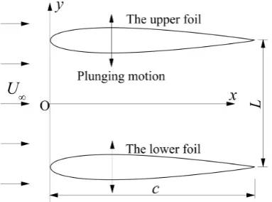
In this paper, a NACA0012 airfoil is used as the contour of the flapping foil, as shown in Figure 1, the flapping motion of the upper foil is described as follow:
(
)
0 sin 2π
y= y +h ft
(1)
where y is the vertical coordinates of the flapping foil, y0 is the vertical
coordi-nate of the mean position of the flapping foil, h is the flapping amplitude, f is the
[image:2.595.279.471.545.687.2]U∞: initial velocity of the flow; L: separation distance between the up-per and lower foils; c: the chord length of NACA0012.
flapping frequency. All the control parameters are non-dimensionalized, the spacing L=L c′ , the flapping amplitude h=h c′ , the flapping frequency
2π
k= fc U∞ . The lower foil flaps counter-phase with the upper foil.
The governing equations of a two-dimensional incompressible viscous flow are written as follows:
( )
1 2p
t Re
∂ + ∇ ⋅ = −∇ + ∇ + ∂
u
uu u f ,
(2)
0
∇ ⋅ =u . (3)
where u is the velocity, p is the pressure, the Reynolds number is defined as Re = LU∞/ν, ν is the viscosity, and f is the Eulerian force density. The parameters in
the current work are defined as follows: U∞ = 1.0, c = 1.0, Re = 500.0. A simple
immersed boundary method [19] is employed to calculate the interacting force between the flapping foil and the surrounding fluid, the solution procedure of the immersed boundary method can be done as the following steps (time ad-vancement from n to n + 1):
( )
( )
1 2(
)
3 1 1
2 2 2
n
n
n n n
p t Re − − = − ∇ + ∇ − ∇ + ∇ + ∆ u u
uu uu u u (4)
( )
( ) (
)
2k =
∑
X δh − k h
u X u x x X (5)
(
)
(
)
(
2)
( )
( ) ( )
1 X
M b k k
h j h k j
j sh t δ δ = − − − ∆ = ∆
∑ ∑
x X x X F X u X u X(6)
( )
1( ) (
)
M
k h k
k=
δ
s=
∑
− ∆f x F X x X (7)
1 * 2 n t + − = ∆ u u
f (8)
** * n p t − = ∇ ∆ u u (9) 1 ** 2pn+
∇ ⋅u = ∇
(10)
1 ** 1 n n p t + + − = −∇ ∆ u u (11)
where u, u* and u** are the intermediate velocity values between the time step of n and n + 1, the complete details of the algorithm and the validations are available in the previous work [20].
3. Results and Discussion
Figure 2. Vorticity contours for the case of an isolated flapping foil with the flapping am-plitude h = (a) 0.1 and (b) 0.35. The other control parameters are k = 4.0, Re = 500. White and black colors denote positive (anticlockwise) and negative (clockwise) vorticity, re-spectively.
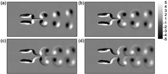
Figure 3. Vorticity contours for the case of dual-flapping foils with the separation dis-tance L = (a) 0.6, (b) 0.8, (c) 1.0 and (d) 1.2. The other control parameters are k = 4.0, h = 0.1 and Re = 500. White and black colors denote positive (anticlockwise) and negative (clockwise) vorticity, respectively.
lected von-Kármán vortex street, was observed behind the dual-flapping foils, and the deflection angle increases as the separation distance decreases. It is very surprising since the Kármán wake of a flapping foil reported in the previous stu-dies was not deflected [6]. Figure 4 shows the wake pattern of dual-flapping foils with the flapping parameters of k = 4 and h = 0.35. The deflected reversed von- Kármán vortex streets have formed behind the flapping foils, but the direction of the deflection is opposite to that of an isolated foil. The deflection weakens as the spacing increases. We should point out that, the wake of dual-flapping foils would not deflect when the spacing is appropriate, although the wake of an iso-lated flapping foil with the flapping parameters of k = 4 and h = 0.35 deflects. It means that the dual-foils not only restrain the wake deflection but also promote the wake deflection.
[image:4.595.212.536.237.381.2]Figure 4. Vorticity contours for the case of dual-flapping foils with the separation dis-tance L = (a) 1.6, (b) 2.0, (c) 2.4 and (d) 2.8. The other control parameters are k = 4.0, h = 0.35 and Re = 500. White and black colors denote positive (anticlockwise) and negative (clockwise) vorticity, respectively.
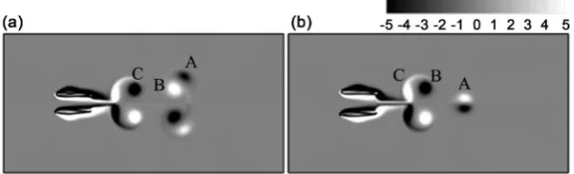
Figure 5. The pairing competition among the first few vortices of dual-flapping foils with different initial motions. (a) the upper foil has an initially upward motion; (b) the upper foil has an initially downward motion. White and black colors denote positive (anti-clockwise) and negative ((anti-clockwise) vorticity, respectively.
ferent to the deflection of the wake behind an isolated flapping foil. The vortex generated in the open flapping motion also followed the vortex produced during the consecutive close flapping motion, no matter the up foil starts with an up-ward or downup-ward motion initially. Figure 5 shows the vortex field at the nas-cent stages after the foils start to move. When the upper foil has an initially up-ward motion, the starting vortex “A” is pairing with the strong vortex “B” gen-erated in the consecutive downward motion. However, when the upper foil has an initially downward motion, the vortex pair formed by the vortex “B” and “C”, instead of the vortex “B” and “A”. This is because the jet flow generated during the close flapping motion can push the vortex to the downstream. Figure 6
[image:5.595.217.533.328.424.2]Figure 6. Plot of the mean streamwise velocity profile showing asymmetric wake for (a) h = 0.1, L = 0.6; (b) h = 0.35, L = 1.6. The other control parameters are k = 4.0 and Re = 500.
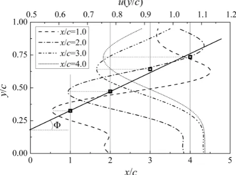
Figure 7. Average wake deflection angle for the case of L = 0.6, h = 0.1 k = 4.0, Re = 500. Φ: the deflected angle. Fine lines indicate four locations in the flow direction (x-direction) for the downstream distances from the trailing edge of the upper foil. Rectangular sym-bols imply locations of maximum mean velocity. Heavy line represents the linear curve- fit which is performed through the rectangular symbols.
recorded, the rectangular symbols represent the locations of maximum value of each mean velocity profiles of the upper foil. The deflection angle is calculated through a linear curve fit (the heaving line) which is performed through the rec-tangular symbols in Figure 7. The results of deflection angle will discuss in the latter.
[image:6.595.254.494.280.458.2]influ-ences the deflection. Here, we calculate the vertical dipole-induced velocity as follows:
(
2π sin)
y
VΓ = Γ
ξ
α
(13) where Γ is the vortex circulation, ξ is the distance between adjacent vortex cores, and α is the angle between the direction of the dipole and the horizontal direc-tion, as shown in Figure 8. The way we used to calculate the vortex circulation Γ follows the previous study [13]. [image:7.595.272.475.380.501.2]
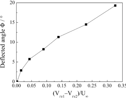
The vertical dipole-induced velocities of two adjacent dipoles define the trend of upward deflecting and downward deflecting, respectively. As shown in Figure 8, the upward deflecting dipole is represented by vortices “I” and “II” which in-duce an upward velocity, and the downward deflecting dipole is represented by vortices “II” and “III” which induce a downward velocity. Figure 9 shows the results of the deflected angle and the vertical dipole-induced velocity in the wake of the upper foil in different simulation series. It shows that, the wake deflects upward when the upward deflecting velocity is larger than the downward def-lecting velocity, and the deflected angle increases as the difference between up-ward and downup-ward deflecting velocities increases. When the downup-ward def-lecting velocity is larger than the upward defdef-lecting velocity, the wake of a flap-ping foil deflects downward, such as the wake of the lower foil in Figure 3(a)
Figure 8. Parameters used in calculating the vertical dipole-induced velocity.
[image:7.595.263.484.532.704.2]and Figure 4(a).
4. Conclusion
The vortex formation of the wake of dual-flapping foils has been numerically studied using the immersed boundary method. Beside the deflection of the re-versed von-Kármán vortex street, an interesting phenomenon, the deflection of the von-Kármán vortex street, was observed behind the dual-flapping foils. The deflected direction is not according to the initial direction of the heaving motion because the vortex generated in the open flapping motion was also pairing with the vortex produced during the consecutive close flapping motion. The deflec-tion trend correlates with the vertical induced velocities of two adjacent dipoles, which represent the trends of upward and downward deflecting, respectively. Moreover, the deflection angle is determined by the difference between upward and downward deflecting velocities. The results may provide some physical in-sights for understanding the intrinsic mechanism in flying and swimming in nature, and the three-dimensional model will be considered in our further work.
Acknowledgements
This work is supported by the National Natural Science Foundation of China (grant number 11462015) and the Aeronautical Science Foundation of China (grant number 2015ZC56007).
References
[1] Jones, K.D., Bradshaw, C.J., Papadopoulos, J., et al. (2005) Bio-Inspired Design of Flapping-Wing Micro Air Vehicles. The Aeronautical Journal, 109, 385-393.
https://doi.org/10.1017/S0001924000000804
[2] Platzer, M.F., Jones, K.D., Young, J., et al. (2008) Flapping Wing Aerodynamics: Progress and Challenges. AIAA Journal, 46, 2136-2149.
https://doi.org/10.2514/1.29263
[3] Wang, Z.J. and Russell, D. (2007) Effect of Forewing and Hindwing Interactions on Aerodynamic Forces and Power in Hovering Dragonfly Flight. PHYSICAL REVIEW LETTERS, 99, 148101 https://doi.org/10.1103/PhysRevLett.99.148101
[4] Liang, B. and Sun, M. (2014) Dynamic Flight Stability of a Hovering Model Dra-gonfly.Journal of Theoretical Biology, 348, 100-112.
https://doi.org/10.1016/j.jtbi.2014.01.026
[5] Koochesfahani, M.M. (1989) Vortical Patterns in the Wake of an Oscillating Airfoil. AIAA Journal, 27, 1200-1205. https://doi.org/10.2514/3.10246
[6] Godoy-Diana, R., Aider, J.L. and Wesfreid, J.E. (2008) Transitions in the Wake of a Flapping Foil. PHYSICAL REVIEW E, 77, 016308.
https://doi.org/10.1103/PhysRevE.77.016308
[7] Schnipper, T., Andersen, A. and Bohr, T. (2009) Vortex Wakes of a Flapping Foil. Journal of Fluid Mechanics, 633, 411-423.
https://doi.org/10.1017/S0022112009007964
[8] Jones, K.D., Dohring, C.M. and Platzer, M.F. (1998) Experimental and Computa-tional Investigation of the Knoller-Betz Effect. AIAA Journal, 36, 1240-1246.
[9] Platzer, J.C.S.L.M.F. (1999) Jet Characteristics of a Plunging Airfoil. AIAA Journal, 37, 1529-1537 https://doi.org/10.2514/2.641
[10] Heathcote, S. and Gursul, I. (2007) Jet Switching Phenomenon for a Periodically Plunging Airfoil. Physics of Fluids, 19, 027104 https://doi.org/10.1063/1.2565347
[11] Von, E.K.D. and Pothos, S. (2007) PIV Measurements of the Asymmetric Wake of a Two Dimensional Heaving Hydrofoil. Experiments in Fluids, 44, 733-745.
[12] Godoy-Diana, R., Marais, C., Aider, J.L., et al. (2009) A Model for the Symmetry Breaking of the Reverse Benard-Von Karman Vortex Street Produced by a Flapping Foil. Journal of Fluid Mechanics, 622, 23-32.
https://doi.org/10.1017/S0022112008005727
[13] Zheng, Z.C. and Wei, Z. (2012) Study of Mechanisms and Factors that Influence the Formation of Vortical Wake of a Heaving Airfoil. Physics of Fluids, 24, Article ID: 103601.https://doi.org/10.1063/1.4760258
[14] Deng, J. and Caulfield, C.P. (2015) Dependence on Aspect Ratio of Symmetry Bre- aking for Oscillating Foils: Implications for Flapping Flight. Journal of Fluid Me-chanics, 787, 16-49.https://doi.org/10.1017/jfm.2015.661
[15] Maraisa, C., Thiriaa, B., Wesfreida, J.E., et al. (2012) Stabilizing Effect of Flexibility in the Wake of a Flapping Foil. Journal of Fluid Mechanics, 710, 659-669.
https://doi.org/10.1017/jfm.2012.390
[16] Zhang, X., Ni, S., Wang, S., et al. (2009) Effects of Geometric Shape on the Hydro-dynamics of a Self-Propelled Flapping Foil. Physics of Fluids, 21, Article ID: 103302.
https://doi.org/10.1063/1.3251045
[17] Zhu, X., He, G. and Zhang, X. (2014) How Flexibility Affects the Wake Symmetry Properties of a Self-Propelled Plunging Foil. Journal of Fluid Mechanics, 751, 164- 183. https://doi.org/10.1017/jfm.2014.310
[18] Peskin, C.S. (2003) The Immersed Boundary Method. Acta Numerica, 11, 479-517. [19] Su, S.W., Lai, M.C. and Lin, C.A. (2007) An Immersed Boundary Technique for Si- mulating Complex Flows with Rigid Boundary. Computers & Fluids, 36, 313-324.
https://doi.org/10.1016/j.compfluid.2005.09.004
[20] He, G.Y., Wang, Q., Zhang, X., et al. (2012) Numerical Analysis on Transitions and Symmetry-Breaking in the Wake of a Flapping Foil. Acta Mechanica Sinica, 28, 1551-1556.https://doi.org/10.1007/s10409-012-0158-8
Submit or recommend next manuscript to SCIRP and we will provide best service for you:
Accepting pre-submission inquiries through Email, Facebook, LinkedIn, Twitter, etc. A wide selection of journals (inclusive of 9 subjects, more than 200 journals)
Providing 24-hour high-quality service User-friendly online submission system Fair and swift peer-review system
Efficient typesetting and proofreading procedure
Display of the result of downloads and visits, as well as the number of cited articles Maximum dissemination of your research work