ISSN Online: 1945-3124 ISSN Print: 1945-3116
Complexity Measure of Software
Composition Framework
Nalinee Sophatsathit
Faculty of Science, Suan Sunandha Rajabhat University, Bangkok, Thailand
Abstract
This article proposes a pragmatic approach to software composition based on matching criteria by mimicking integrated hardware counterpart. The tangi-ble value of consumer goods as described by Cox instills this logical derivation of the proposed approach. As software gradually matures in component form, various software compositions can be systematically assembled from related existing software. Two application software are composed based on their functionality matching. Their composition complexities are measured by function point. The total effort unveils a noteworthy finding that high com-plexity software demands larger effort to deploy. Thus, the proposed software composition framework not only offers the freedom of development man-dates to the development team, but also broadens the horizon of cost and project evaluations by arriving at the proper mix of constituent components in the software product.
Keywords
Software Composition, Functionality Matching, Function Point, Complexity Measure
1. Introduction
The proliferation of software application in daily operations is undeniably deep- rooted and intertwined with every fabric of life. Complicated as software systems are, they evolve in much the same manner as the chaotic world of their creator. The advent of personal computer has brought about myriad of applications op-erated and supported by software bundles. Yet no one complains about the shortcomings of these heterogeneous software systems created by unassociated developers that were never meant to interoperate. Nonetheless, new develop-ment paradigms such as structured, modular, object-oriented, and aspect- oriented approaches were employed to accommodate and exploit software ap-How to cite this paper: Sophatsathit, N.
(2017) Complexity Measure of Software Composition Framework. Journal of Soft-ware Engineering and Applications, 10, 324-337.
https://doi.org/10.4236/jsea.2017.104019
Received: February 15, 2017 Accepted: April 10, 2017 Published: April 13, 2017
Copyright © 2017 by author and Scientific Research Publishing Inc. This work is licensed under the Creative Commons Attribution International License (CC BY 4.0).
http://creativecommons.org/licenses/by/4.0/
N. Sophatsathit
plications to their fullest extent. Business values were added, whereby new soft-ware services were created. This in turn elevated softsoft-ware use to a new level of sophistication. Strategic software application has transformed the development paradigm into component-based development (CBD). As such, new software compositions can be deployed with less effort by means of reuse, plug-and-play, and other composition techniques. The evidence will become clearer as devel-opment efforts are measured quantitatively by means of Function Point estab-lished by Albrecht, etal.[1].
Meanwhile, software architects and engineers are working hard to mimic the design and construction processes of its counterpart. Hardware components are standardized to furnish product diversification. Special purpose hardware can be fabricated to fulfill the desired functionality in a relatively straightforward and time/cost saving manner. The design and construction processes are concep-tually and technically similar to each other since the processes receive greater level of attention and scrutiny to be reused, streamlined, and automated. They are firmly established as tangible goods [2]. Software products, on the other hand, must have gone through various development stages before delivery, yet they are still far from standardization in comparison to their hardware counter-part.
Bearing such problems in mind, one of the new challenges in software devel-opment is how to build software by composition technique from the existing software or software components. The principal consideration is to determine how well the constituent components interoperate. This implies matching of component functionalities. The issue will be further explored in the remaining sections of this article.
This paper is organized as follows. Section 2 recounts some related work on software component. Section 3 describes the proposed software component and its matching criteria. A concise case study is given to demonstrate the viability and performance of the proposed approach in Section 4. Section 5 presents some final thoughts and future enhancement.
2. Related Work
does not come without certain prices: well-defined interface, deployment policy, verification/monitoring/maintenance of software components, and integration of operations.
One of the prominent technique was established by Parnas [4] that used key-word in context (KWIC), consisting of task, a set of lines of text as input, and the set of all circular shift of all lines in alphabet order as output. He was the first to describe how software architecture guided modifiability via shared data model and data abstraction model. As the scale of software functions and operations expands, arrays of support services and measurements are called for. Various research endeavors have been attempted on software engineering environments
[5] [6]. Ironically, software engineering environments in primitive integrated
development environment (IDE) forms have been around since the introduction of Ada Programming Support Environment (APSE). APSE and its derivatives, Common APSE Interface Set, (CAIS) [5], as well as their competing develop-ment environdevelop-ment family—the Portable Common Tool Environdevelop-ment (PCTE) and PCTE+ [6], were the two most comprehensive but homogeneous Integrated Programming Support Environments (IPSE) then. More environment specifics, such as PNMPI inter-tool communication [7], offered dynamic loading and concurrent use at the expense of some infrastructure compliance overhead.
The expansion of distributed processing also imposes additional interopera-bility requirements among software composition techniques. Interoperainteropera-bility is usually achieved through API, message interfaces, command-line options [8], as well as an information structure model describing the communication bindings between Tool Communications [9] structures. These endeavors exemplify the needs for resolving heterogeneity that may exist among software composition. Some approaches handled the issue by means of Workflow Management
Coali-tion [10], as well as meta-data and ontology mechanisms [11] to ensure reliable
operation of intercommunicating systems.
Modern software development is fast-paced and short-lived. New releases come out every other week. Competing apps are available for test drive on a weekly basis. The development process has to adapt COTS components that take care of the aforementioned technical issues without reinventing the wheel. Thus, the emphasis should be focused on software composition guideline and tech-nique that permit timely and correctly functioned software. Unfortunately, the irreducible essence such as complexity, conformity, changeability, and
invisibil-ity [12] make software construction difficult. We will look into some of software
composition issues to establish a proposed software composition framework. Some details will be further elaborated in the next section.
3. Proposed Approach
N. Sophatsathit
integration in heterogeneous environments by exposing the meta-component model and constructs to supporting technologies. Interoperability enhancement can be further fine-tuned with the help of dynamic and late binding mechanisms as software is executed in the form of a separated application. Unfortunately, these provisions inevitably introduce a new layer of human interconnecting complexity ranging from command language semantic, analysis and design ab-stractions, user-friendliness overhead, code and style legibility restrictions, and so on.
Bearing the above issues in mind, we propose a framework for component composition that encompasses the following attributes:
well-defined component composition technique
self-contained and loosely-coupled building blocks
Such provisions call for a suitable integration technique to ensure their proper operations. Modern software development paradigms, prevalent as they are, fo-cus on the commonality of processing format to facilitate interoperability. The good old notion of IDE has been rejuvenated as a means for creating, operating, integrating, storing, retrieving, and maintaining of the desired information. Un-fortunately, most IDEs operate on homogeneous basis, whereby foreign data must undergo format conversion upon importation, let alone the software itself. In so doing, the ultimate goal of the IDE as being truly interoperable is defeated. Moreover, the extraneous data and format conversions inevitably introduce ad-ditional processing burden that, in many cases, does not justify the efforts in ex-change for imperfect conversion and information loss. At any rate, newer IDEs/ IPSEs are more commonplace in development community, e.g., the .NET, EJB, and CORBA, yet still preserve their locality. For all practical composition pur-poses, any foreign software or tools must comply with the underlying mandate in order to co-exist.
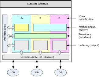
The proposed framework for software composition matching will therefore entail flexible and extensible development methodology of problem solving software components. In order to align different software functionalities with user’s requirements, all pertinent interfaces must, to some degree, match with the requirements. The principal directive of the proposed composition frame-work is the matching strategy that covers the constituent components. Case in point, as depicted in Figure 1, the matching strategy sets a stage for three soft-ware component development, namely, A, B, and C. Component A requires that its input be exclusive, while B and C presumably share common input interface. Once complete, input artifacts must undergo the same set of development tran-sition so as to preserve the matching requirement. Nonetheless, the eventual output operations are individually crafted to best satisfy each matching require-ment so established.
Figure 1. Software composition framework.
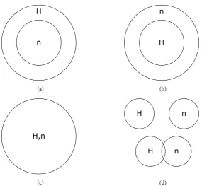
process, two considerations that must be taken into account are service require-ment identification and granularity of service. Praserttitipong, et al. [14] [15] proposed some formalities of requirement identification to quantitatively assess the matching process. Three component acquisition requirements were estab-lished, namely, plug-in match, subsume match, and exact match. Situations arise when selective or no match occurs, thereby matching scenarios precipitated from the above requirements are proposed and summarized in Figure 2. The plug-in match of Figure 2(a) represents extraneous functions offered by the composite software (H) that exceed what the user (n) requests. Thus, the set of available functions becomes,
{ ,},
{
, extra}
n i H n i n
S =U∈ S = S
where extra∈SH. By the same token, subsume match yields
{ ,},
{
, deficit}
n i H n i H
S =U∈ S = S , which still falls short of user satisfaction. The exact match, on the contrary, is the ideal scenario of software composition, while miss-out match is obviously irrelevant. The partial match, in general, calls for some degrees of customized tailoring in the form of wrapper or derivation. As such, it remains to be a problematic matching issue to reckon with.
From the development standpoint, software component is fundamentally composed of a set of operational methods that, in turn, are derived from some predecessor base methods. Let Hi and ni denote the ith component of the existing
software and user’s request, respectively. Notationally, Hi = {sm1,sm2,…, smj}
denotes the set of constituent component methods, i.e., component method 1, component method 2, and so on. Similarly, ni = {rm1,rm2,…,rmk} denotes the
set of the matching methods, i.e., matching method 1, matching method 2, and
External interface
Class specification
method(input, inquiry)
A B C
Transitions (interface)
in
te
rm
ed
ia
ri
es
Mediation(internal interface)
DB DB DB
N. Sophatsathit
(a) (b)
(c) (d)
Figure 2. Software component acquisition matching: (a) plug-in match; (b) subsume match; (c) exact match; and (d) partial/miss-out match.
so on. Moreover, j ≠ k. The partial match process is to find subsets of Hi that cover as much of each rmi as possible. The partial matching procedure proceeds
as follows:
Initialization Foreachrmiofni
Getfirstmethodofsmi
Whilenot((matchorpartialmatch[rmi,smi])andend_method_list)
ni'∪rmi //collectsetcomplementni'
Getnextmethodofsmi
Ifmatchrmiorpartialmatchrmi
ni∪(smiorni\smi)//\symboldenotespartialmatch
end_foreach
Thus, the resulting ni will be partially covered by some smi of Hi that match
the corresponding rmi, i.e., ni={smi| \smi, where smi∈Hi,smi⊂rmi}. The miss-
out match of smj, denoted by ni'={rmi,wherermi∈ni}, constitutes the set
com-plement of ni which must be either imported or purchased from external
sources, locally built, or outsourcing under the pre-established governance. The last two choices required additional customization efforts.
Irrespective of which matching process will fit final business process, it is ap-parent that the proposed framework by and large offers dynamic inherent provi-sions for different software component composition schemes. As a consequence, development delegation can stay focus on the more important tailoring strategy, yet still operationally maintain composition compliance with user’s require-ments.
n H
H n
H,n
H n
(a) (b)
H,n
H n
H n
[image:6.595.230.516.66.329.2]4. Case Study
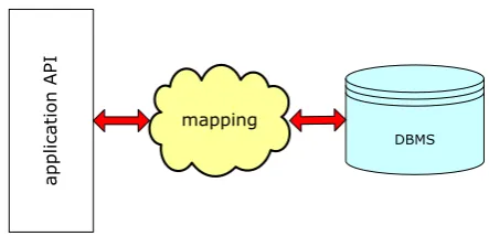
[image:7.595.261.483.610.717.2]A small web-database application was set up to demonstrate the viability of the proposed composition framework. The application consisted of a conventional front-end software and standard back-end database management systems (DBMS). The software components were mutually independent but logically connected through a software connectivity map. The configuration is depicted in
Figure 3.
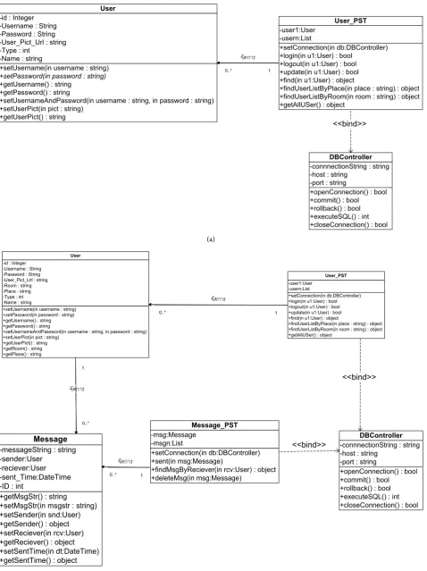
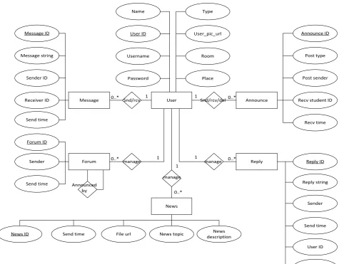
Figure 4(a) and Figure 4(b) illustrate a few sample class diagrams of the
front-end application interfaces (APIs) to interact with the users. Figure 5 shows the available functionality of a typical DBMS.
The very core of this web-database application is the design and construction of the software connectivity map that must follow the established (business) op-erational objectives and Internet standards. The map construction is carried out as follows:
1. set up the matching policy according to the established operational objectives. 2. design, either in-house or delegation/outsourcing, the required front-end API
components and back-end DBMS functions based on the proposed software component acquisition requirements.
initialization
-collect the number of API classes and their corresponding attributes rmi in ni
-collect the number of entity templates and their attributes from the available DBMS in templatei
for each rmi of ni
get all pertinent attributes that are manipulated by the class method
while not (match([attrib_class_methodi, templatei]) and end_attrib_class_
method_list)
get next attrib_class_method if matchrmiorpartialmatchrmi
ni∪ (templatei or ni\templatei )
end_for each
3. consider for all practical composition purposes, plug-in match is the best sce-nario since extra DBMS functions available mean ease of future feature en-hancement. Other matching scenarios such as exact match yield a sufficient solution but do not leave any room for expansion; subsume match and partial match call for additional development efforts, time, and costs.
Figure 3. Software operational mapping between front-end and back-end.
mapping
DBMS
N. Sophatsathit
(a)
[image:8.595.61.540.68.708.2](b)
Figure 4. (a) Front-end class diagram; (b) Front-end class diagram. +setUsername(in username : string)
+setPassword(in password : string) +getUsername() : string
+getPassword() : string
+setUsernameAndPassword(in username : string, in password : string) +setUserPict(in pict : string)
+getUserPict() : string -id : Integer
-Username : String -Password : String -User_Pict_Url : string -Type : int
-Name : string
User
+setConnection(in db:DBController) +login(in u1:User) : bool
+logout(in u1:User) : bool +update(in u1:User) : bool +find(in u1:User) : object
+findUserListByPlace(in place : string) : object +findUserListByRoom(in room : string) : object +getAllUSer() : object
-user1:User -usern:List
User_PST
+openConnection() : bool +commit() : bool +rollback() : bool +executeSQL() : int +closeConnection() : bool -connnectionString : string -host : string
-port : string DBController จัดการ
0..* 1
<<bind>>
+setUsername(in username : string)
+setPassword(in password : string)
+getUsername() : string +getPassword() : string
+setUsernameAndPassword(in username : string, in password : string) +setUserPict(in pict : string)
+getUserPict() : string +getRoom() : string +getPlace() : string -id : Integer -Username : String -Password : String -User_Pict_Url : string -Room : string -Place : string -Type : int -Name : string
User
+setConnection(in db:DBController) +login(in u1:User) : bool +logout(in u1:User) : bool +update(in u1:User) : bool +find(in u1:User) : object
+findUserListByPlace(in place : string) : object +findUserListByRoom(in room : string) : object +getAllUSer() : object
-user1:User -usern:List
User_PST
+openConnection() : bool +commit() : bool +rollback() : bool +executeSQL() : int +closeConnection() : bool -connnectionString : string -host : string
-port : string DBController จัดการ
0..* 1
+getMsgStr() : string +setMsgStr(in msgstr : string) +setSender(in snd:User) +getSender() : object +setReciever(in rcv:User) +getReciever() : object +setSentTime(in dt:DateTime) +getSentTime() : object -messageString : string -sender:User
-reciever:User -sent_Time:DateTime -ID : int
Message
+setConnection(in db:DBController) +sent(in msg:Message)
Figure 5. Samples back-end DBMS functions.
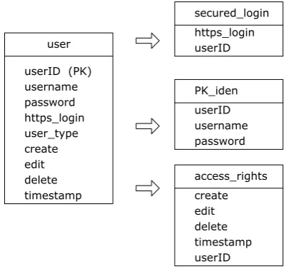
4. conduct detailed design as a transitional tailoring to adjust the software com-position in concert with operating formats and standards. In this case, devise all front-end API artifacts, logic, look and feel, etc., following the Internet op-erational standards and services. This may require involvement as the devel-opment life cycle of new e-business practices, policies, law enforcement, and technology shrink. Consultation with the intermediaries is thus necessary so that minimal development endeavor will be expended. Latest available IDE service supports, ontology discovery, and the likes are also carried out at this stage. As depicted in Figure 6, the Person_API class was split into three mes-sage groups, namely, secured_login/PK_iden/access_rights, and NULL/NO_ iden/access_list, representing registered and general users, respectively. 5. a final touch-up is performed to ensure that the application complies with the
mediation interface, i.e., browser, platform, and other communication discip-lines.
Effort assessment of application (or apps) was measured by Function Point (FP). The method was first defined by Albrecht [16] as “a methodology to estimate
Name Type
User ID User_pic_url
Username Room
Password Place
User
Message 0..* Snd/rcv 1 1 Snd/rcv/del0..* Announce
Forum 0..* manage 1 1 manage 0..* Reply
Message ID
Message string
Sender ID
Receiver ID
Send time
Announce ID
Post type
Post sender
Recv student ID
Recv time
manage
News
File url News topic
Send time descriptionNews
News ID
Reply ID
Sender
Send time
User ID
Forum ID Reply string Forum ID
Sender
Send time Announced
by 0..*
N. Sophatsathit
Figure 6. Message splitting.
the amount of the “function” the software is to perform, in terms of the data it is to use (absorb) and to generate (produce). The “function” is quantified as “func-tion points”, essentially, a weighted sum of the numbers of “inputs”, “outputs”, “master files”, and “inquiries” provided to, or generated by, the software.” The method was later refined by Albrecht and Gaffney [1]. Thus, the Function Point Analysis (FPA) is essentially based on five different functional artifacts which are further exemplified by Finnie, etal. [17] as shown in Table 1. For example, a simple app consisting of two inputs, two outputs, three inquiries, one interface file, and one internal file will be equal to 35 FP (2 * 3 + 2 * 4 + 3 * 3 + 1 * 5 + 1 * 7).
The experimental data from the above case study are shown in Table 2. Fac-tors of measurement were classified in accordance with the above Function Point allocation guideline. Thus, the external input, output, inquiry, interface file, and internal file were classified as simple, average, average, complex, and average, whose scores were 3, 5, 4, 10, and 10, respectively.
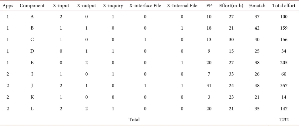
Table 3 shows the experimental results obtained from two apps, namely, 1
and 2 (to keep their anonymity) having different functional components. The number of external inputs, outputs, inquiries, interface files, and internal files are also listed. The corresponding function points were determined according to the above guideline. The matching assessment was determined from their matching percentage of service functionality. The actual development efforts were taken by man-hour (m-h).
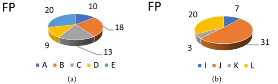
Figure 7(a) and Figure 7(b), Figure 8(a) and Figure 8(b) depict the
propor-tional FP and total effort results by apps, respectively. It can be drawn from the results that the higher the FP is, the more effort must be expended in order to tailor the service to suit the user’s needs.
Figure 9(a) and Figure 9(b) show the FP and total effort of all components
from both apps, respectively. The same conclusion can be drawn of the rela-tionship between FP and total effort.
user
userID (PK) username password https_login user_type
edit delete timestamp create
userID https_login secured_login
PK_iden
username
access_rights password userID
edit delete timestamp create
[image:11.595.233.520.72.159.2]
(a) (b)
Figure 7. (a) Function point by apps; (b) Function point by apps.
[image:11.595.213.537.77.446.2]
(a) (b)
Figure 8. (a) Total effort by apps; (b) Total effort by apps.
[image:11.595.212.536.308.408.2](a) (b)
Figure 9. (a) FP and total effort; (b) FP and total effort.
Table 1. Function point allocation.
Description Simple Average Complex
External Input 3 4 6
External Output 4 5 7
External Inquiry 3 4 6
External Interface File 5 7 10
Internal File 7 10 15
Table 2. Experimental data.
Factor Type Score
External Input simple 3
External Output average 5
External Inquiry average 4
External Interface File complex 10
[image:11.595.210.540.464.583.2]N. Sophatsathit
Table 3. Experimental results.
Apps Component X-input X-output X-inquiry X-interface File X-Internal File FP Effort(m-h) %match Total effort
1 A 2 0 1 0 0 10 27 37 100
1 B 1 1 0 0 1 18 21 42 159
1 C 1 0 0 1 0 13 30 40 156
1 D 0 1 1 0 0 9 15 25 34
1 E 0 2 0 0 1 20 27 38 205
2 I 1 0 1 0 0 7 33 26 60
2 J 2 1 0 1 1 31 24 48 357
2 K 1 0 0 0 0 3 23 21 14
2 L 2 2 1 0 0 20 21 35 147
Total 1232
A noteworthy benefit precipitating from the proposed framework that was conducive toward the complete case study shown in Figure 3 was freedom of development mandates. Front-end development team, in particular, could focus on their user requirements to best tailor the final deliverable with little concern with back-end integration issues. Similarly, back-end development team could procedurally build customized (or generalized) functionalities and modules to support different functionalities. New software components could be established through this operational map reuse as generic connectors. Therefore, the asso-ciated costs and resources could be procedurally estimated to assess the viability of project management.
5. Conclusion and Future Work
References
[1] Albrecht, A. and Gaffney, J.J. (1983) Software Function, Source Lines of Code, and Development Effort Prediction: A Software Science Validation. IEEE Transactions onSoftwareEngineering, SE-9, 639-648.https://doi.org/10.1109/TSE.1983.235271 [2] Cox, B. (1995) No Silver Bullet Revisited. AmericanProgrammerJournal, 8. [3] Waldo, J. (1999) The JINI Architecture for Network-Centric Computing.
Commu-nicationsoftheACM, 42, 76-82. https://doi.org/10.1145/306549.306582
[4] Parnas, D.L. (1972) On the Criteria to Be Used in Decomposing Systems into Mod-ules. CommunicationsoftheACM, 15, 1053-1058.
https://doi.org/10.1145/361598.361623
[5] Common APSE Interface Set, MIL-STD-1838A, 30 September 1989.
[6] ECMA Technical Committee (TC33)—ECMA TR/55 (1990) A Reference Model for Frameworks of Computer-Assisted Software Engineering Environments. European Computer Manufacturers Association, Geneva.
[7] Schulz, M. and de Supinski, B.R. (2006) A Flexible and Dynamic Infrastructure for MPI Tool Interoperability. International Conference on Parallel Processing, Co-lumbus, 14-18 August 2006, 193-202.https://doi.org/10.1109/icpp.2006.6
[8] Bao, Y. and Horowitz, E. (1996) A New Approach to Software Tool Interoperability. Proceedings ofthe 1996 ACMsymposium onApplied Computing, Philadelphia, 17-19 February 1996, 500-509.https://doi.org/10.1145/331119.331432
[9] Harvey, J.G. and Marlin, C.D. (1996) A Layered Operational Model for Describing Inter-Tool Communication in Tool Integration Frameworks. Proceedingsof 1996 AustralianSoftwareEngineeringConference, Melbourne, 14-18 July 1996, 55-63.
https://doi.org/10.1109/ASWEC.1996.534123
[10] El-Khatib, H.T., Williams, M.H., Marwick, D.H. and Mackinnon, L.M. (2002) Using a Distributed Approach to Retrieve and Integrate Information from Heterogeneous Distributed Databases. TheComputerJournal, 45, 381-394.
https://doi.org/10.1093/comjnl/45.4.381
[11] Arch-int, N. and Sophatsathit, P. (2003) A Semantic Information Gathering Ap-proach for Heterogeneous Information Sources on WWW. JournalofInformation Science, 29, 357-374.https://doi.org/10.1177/01655515030295003
[12] Brooks, F.P. (1986) No Silver Bullet—Essence and Accidental in Software Engi-neering. In: Kugler, H.-J., Ed., Proceedings of the IFIP 10th World Computing Conference, Elsevier Science, Amsterdam, 1069-1076.
[13] Sauer, L.D., Clay, R.L. and Armstrong, R. (2000) Meta-Component Architecture for Software Interoperability. ProceedingsoftheInternationalConferenceonSoftware MethodsandTools, Wollongong, 6-9 November 2000, 75-84.
https://doi.org/10.1109/swmt.2000.890423
[14] Praserttitipong, D. and Sophatsathit, P. (2007) A Synopsis Model for Deterministic Behavioral Specifications of an Adaptable Agent. Proceedingsof the 5th Interna-tional Conference onSoftware EngineeringResearch, Management and Applica-tions, Busan, 20-22 August 2007, 655-661.https://doi.org/10.1109/sera.2007.35 [15] Praserttitipong, D. and Sophatsathit, P. (2007) A Framework for Deterministic
In-tention Specifications of an Agent toward an Incomplete Declared InIn-tention. Pro-ceedingsofthe 6th IEEE/ACISInternationalConferenceonComputerand Infor-mationScience, Melbourne, 11-13 July 2007, 170-175.
N. Sophatsathit
[17] Finnie, G.R., Wittig, G.E. and Desharnais, J.-M. (1997) A Comparison of Software Effort Estimation Techniques: Using Function Points with Neural Networks, Case-Based Reasoning and Regression Models. JournalofSystemsandSoftware, 39, 281-289.
Submit or recommend next manuscript to SCIRP and we will provide best service for you:
Accepting pre-submission inquiries through Email, Facebook, LinkedIn, Twitter, etc. A wide selection of journals (inclusive of 9 subjects, more than 200 journals)
Providing 24-hour high-quality service User-friendly online submission system Fair and swift peer-review system
Efficient typesetting and proofreading procedure
Display of the result of downloads and visits, as well as the number of cited articles Maximum dissemination of your research work