Using a Graphical Design Tool for Formal
Specification
Colin Snook and Michael Butler
Department of Electronics and Computer Science
University of Southampton
Highfield, Southampton, SO17 1BJ, United Kingdom.
{cfs98r,M.J.Butler}@ecs.soton.ac.uk
Keywords: POP-II.B. formal specification, POP-III.D. visualisation, POP-V.A. mental models
Abstract
Formal languages enable the behaviour of a system to be precisely specified and verified. However, even experienced users admit that creating useful models is difficult and this is a barrier to more widespread use. One reason for this is the lack of tools to assist in the modelling process. The process of formal specification is, in many ways, similar to that of programming where design notations and tools have evolved over many years. In this paper we suggest the adaptation of a graphical design notation (UML) for formal specification and support this with a prototype tool to perform automatic translation into a B specification.
Introduction
Experienced formal methods users report that reading and understanding formal specifications is not a significant problem (Snook & Harrison 2001). With suitable training, programmers find formal specifications no more difficult to understand than programs. On the other hand the same users reported that creating formal specifications is very difficult. They said that the main difficulty lies in finding useful abstractions. This indicates that the problem lies not in specifying the detailed semantics but in the preliminary stage of choosing the objects and data structures that make up the model.
extent but not with such a strong motivation. Now the problems being tackled are more complicated the need for formal specification is greater, but in terms of tools and techniques to aid the modelling process it lags behind those of programming. We believe that graphical modelling tools similar to those used for program design would aid the process of formal specification. With this in mind we have developed a prototype program to convert an adapted form of UML (Rumbaugh et.al. 1998) class diagrams into specifications in the B language (Abrial 1996). The aim is to use some of the features of class diagrams to make the process of writing formal specifications easier, or at least more approachable to average programmers. The translation relies on precise expression of additional behavioural constraints in the specification of class diagram components. These constraints are described in an adapted form of the B notation. The type of diagrams that can be converted is restricted in order to comply with constraints of the B-method without making the B unnatural. The UML diagram is a precise formal specification but in a form which is more friendly to average programmers, especially if they use the same UML notation for their program design work. The diagrammatic notation and tool support brings the benefits of its assistance to the modelling process for formal specification. The translation to textual B specification does not add anything to the specification; it merely provides an alternative textual form. In this textual form, however, the benefits of the B method are obtained. The translation also demonstrates the validity of the graphical form and defines its semantics. We envisage benefits to B users (especially novices) from being able to develop models in the UML diagrammatic form and we see this as a possible way to overcome some of the psychological barriers that programmers have against formal specification.
Benefits of a Diagrammatic Form for Specification
representations, although often more accurate in conveying precise meanings, are much more cumbersome for creating some aspects of these models. Graphical representations are good for helping to visualize structures, composition and the relationships between elements. Modelling large systems usually requires initially a structural design, which is then populated with more precise semantic detail. It is this first modelling stage that benefits from program design tools such as UML. Class diagrams allow the types of objects in the problem domain and the relationships between them to be modelled, visualized, prototyped and altered quickly. Attempts to add the semantic detail to these models may result in deficiencies in the model being discovered and lead to refinements to the model. These changes can be made quickly because the model is highly visible and easily alterable with the aid of the graphical design tools. Readability and ambiguity is not an issue because it is the creators that are using the tools for modelling. These features have made graphical design techniques such as UML popular for developing programs. We contend that the process of writing formal specifications is very similar to programming and involves similar difficulties in structural modelling and its visualization. Therefore tools that programmers have evolved for writing programs or ones very similar to them should bring similar benefits when writing specifications.
The B Language and Toolkit
operations of the including machine. A weaker form of interfacing between machines is provided by 'USES'. The using machine has only read access to the used machines variables and cannot invoke its operations. A machine may be used by any number of other machines but may only be included (or extended) by one other machine.
Benefits of Translating UML to B
The translatable UML class diagram with formal annotations is just as precise and complete as the equivalent B specification. This is demonstrated by the fact that it can be translated to B automatically. However, there are still benefits to translating into a B specification:
• The textual B specification may be more readable to experienced formal methods users
• The B specification is mathematically manipulable enabling reasoning and proof to be performed
• The B toolkit is available for type analysis, proof assistance and animation
• The translation demonstrates the semantics of the UML version. A B specification can be animated with the B Toolkit to explore the dynamic behaviour of the modelled system. In UML terms this means that operations of an object can be invoked and the B animator will check pre-conditions, and invariants and display the new state of the system in terms of the object's attributes and relationships with other objects. Animation is useful, especially to novices, because it provides feedback and debugging of the specification. It is also essential for validation, i.e. demonstrating to users that the specification describes a system which will be useful.
A class' dynamic behaviour can be proven to conform to the class’ invariants. In UML terms this means that the proof tools will provide assistance in proving that no sequence of invocations of an object's operations can produce a resultant state (in terms of the class' attributes and associations with other objects) that disobeys the invariant. A safety or business critical property of the system could be specified and verified in this way.
UML models prepared for translation to B contain verified invariant and method descriptions (constraints) in a rigorous, abstract notation. The UML diagram is given a precise semantics as expressed by its equivalent form in the B notation.
U2B Translator
The U2B translator converts Rational Rose1 UML Class diagrams into
the B notation. U2B is a script file that runs within Rational Rose and converts the currently open model to B. It is written in the Rational Rose Scripting language, which is an extended version of the Summit BasicScript language. U2B is configured as a menu option ("Export to B") under the File menu of Rose. U2B uses the object-oriented libraries of the Rose Extensibility Interface to extract information about the classes in the logical diagram of the currently open model. The object model representation of the UML diagram means that information is easily retrieved and the program structure can be based around the logical information in the class rather than a particular textual format. U2B uses Microsoft Word972 to generate the B Machine files via the OLE
interface. The Rose Script uses the object oriented document model of Word97 in order to facilitate the creation of the B Machines. Word template files are used to form the basic layout of the Machines.
Translation of Structure and Static Properties
The translation of Classes, attributes and operations is derived from proposals for converting OMT to B (Meyer & Souquieres 1999). A separate machine is created for each class and this contains a set of all possible instances of the class and a variable that represents the subset of current instances of the class. Attributes and (unidirectional) associations are translated into variables with their type defined in the invariant clause of the machine as a relation from the current instances to the UML attribute type or association class. Types can be any of the predefined types of B (including boolean and string which are B library types) or another class. If the type is neither of these it will be added as a parameter of the machine. When the type is another class the machine for that class will either be extended (EXTENDS) by this machine if there is a path of unidirectional associations to that class or otherwise used (USES). Types can also be a set or sequence of any of these by putting POW(typename) or seq(typename) respectively as the type in the UML class specification. U2B could easily be extended to cover other B data structures in a similar manner. A create operation is automatically provided for each class machine. This picks any instance that isn't already in use, adds it to the
current instances set, and adds a maplet to each of the attribute relations mapping the new instance to the appropriate initial value. Note that, according to our definition (via translation) of class diagrams, association means that the source class is able to invoke the methods of the target class. Non-navigable (and bi-directional) associations are ignored but may be used to illustrate the use of another class as a type (i.e. read access only). The B method imposes some restrictions on the way machines can be composed. These restrictions ensure compositionality of proof. Their impact is that no write sharing is allowed at machine level (i.e. a machine may only be included or extended by one other machine). We reflect these restrictions in the UML form of the specification, which must therefore be tree like in terms of its unidirectional associations. Although we would like to adhere to the UML class diagram rules as much as possible, since our aim is to make B specification more approachable rather than to formalise the UML we are relatively happy to impose restrictions on the diagrams that can be drawn. That is we only define translations for a subset of UML class diagrams. Other authors (Facon et.al. 1996, Meyer & Souquieres 1999, Meyer & Santen 2000, Nagui-Raiss 1994, Shore 1996) have suggested ways of dealing with the translation of more general forms of class diagrams. However, the structures of B machines that result from these translations are not natural. If the specification were written directly in B, it would be highly unlikely that the resulting B would have this form. Since we also desire a usable B specification we prefer to restrict the types of diagrams that can be drawn.
Dynamic Behaviour
the universal quantification over all instances of self. The last invariant is a class wide invariant that specifies properties that hold between the different instances of the class. Here, the quantification is an integral part of the property and must be given explicitly. Hence, U2B will not need to add quantification over instance references. The invariants are separated from any natural language description by the word INVARIANT: . UML does not impose any particular notation for these operation and invariant constraint definitions; they could be described in natural language or using UML's Object Constraint Language (OCL). However some problems have been raised with OCL (Vaziri & Jackson 1999) and since we wish to end up with a B specification it makes sense to use bits of B notation to specify these constraints. The B is close to B notation but has to observe a few conventions in order for it to become valid B within the context of the machine produced by U2B. For example, all operation outputs are called 'Return'. When writing these bits of B the specifier shouldn't need to consider how the translation would represent the features (associations, attributes and operations) of the classes. Also we felt we should follow the more object oriented conventions of implicit self-referencing and use of the dot notation. Therefore when writing the B a dot notation is used to reference the ownership of features, e.g. if class A has an association to class B we might write AassocB.Battr, where AassocB is an association from class A to class B and Battr is an attribute of class B. This would be translated to Battr(AassocB(Aself)).
Example
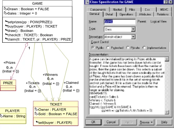
The example in Fig. 1 shows a class GAME that has typed and initialised attributes, parameterised operations (some with return values), three association relationships with a class TICKET and an aggregate relationship with another class, PRIZE. The class also uses another class, PLAYER, as a type. The associations have role names Prizes, Tickets, Winners and Claimed, which are used to refer to the instances of the associated class involved in the association. Alongside the class diagram is shown the Rational Rose specification for the class GAME. Following the natural language description in the 'Documentation' box some class invariants are given. The Atelier B proof tools were used to prove that these invariants were preserved by the operations of the example.
The second part of this expression is a generalised union of the association Tickets over all instances of the parent class, GAME . This is
Fig. 1. Example Class Diagram and Class Specification
precondition
Prizes /= {} & Winners = {} &
TICKET-UNION(gg).(gg:GAME|gg.Tickets) /= {}
semantics
ANY tt WHERE tt: TICKET -
UNION(gg).(gg:GAME|gg.Tickets) THEN
Tickets := Tickets \/ {tt} || tt.sell(buyer) ||
Sales := Sales +1 || Return := tt END
Fig. 2. Precondition and semantics for operation buyof class GAME
PRIZE
TICKET Owner : PLAYER Sold : Boolean = FALSE
sell(buyer : PLAYER) GAME
Drawn : Boolean = FALSE Sales : Integer = 0
setprizes(pp : POW(PRIZE)) buy(buyer : PLAYER) : TICKET draw() : Boolean
check(tt : TICKET) : Boolean claim(tt : TICKET, pl : PLAYER) : PRIZE
0..n 1
+Prizes 0..n
1
0..n +Tickets
0..n 0..n +Winners
0..n
0..n +Claimed
0..n {Initial = {}}
PLAYER Name : String
{Initial = {}}
expressed as the union of gg.Tickets for all gg:GAME. Also, note the call to a method (sell) of the Tickets class. The method is called for the instance tt of TICKET.
Conclusions
A graphical modelling tool is invaluable for developing structural models of systems. This has led to the popularity of tool supported modelling languages such as UML. By adding precise semantic details in the form of specification texts and defining a particular meaning to the diagrammatic features we can interpret some UML diagrams as formal specifications. We have implemented a prototype add-in tool that translates these diagrammatic specifications to B. We believe that the diagrammatic form of formal specification will assist in the difficult task of creating appropriate models and will make formal specification more approachable (especially to novices). In future work we intend to use the translator to evaluate this hypothesis.
References
1. Abrial, J.R. (1996) The B Book - Assigning Programs to Meanings. Cambridge University Press, ISBN 0-521-49619-5
2. Facon, P., Laleau, R., & Nguyen, H. (1996) Mapping Object Diagrams into B Specifications. In Methods Integration Workshop, Electronic Workshops in Computing (eWiC), Springer Verlag.
3. Meyer, E. & Souquieres, J. (1999) A Systematic approach to Transform OMT Diagrams to a B specification. FM'99 LNCS1708 1, 875-895 4. Meyer, E. & Santen, T. (2000) Behavioural Conformance Verification in an
Integrated Approach Using UML and B. In IFM'2000 : 2nd International Workshop on Integrated Formal Methods.
5. Nagui-Raiss, N. (1994) A Formal Software Specification Tool Using the Entity-Relationship Model. In 13th International Conference on the
Entity-Relationship Approach, LNCS 881.
6. Petre, M. (1995) Why Looking Isn’t Always Seeing. Comm. Of the ACM. 38(6)
7. Rumbaugh, J., Jacobson, I. & Booch, G. (1998) The Unified Modelling Language Reference Manual. Addison-Wesley, . ISBN 0-201-30998-X 8. Shore, R. (1996) An Object-Oriented Approach to B. In Putting into
Practice Methods and Tools for Information System Design - 1st Conference on the B method.
10. Vaziri, M. & Jackson, D. (1999) Some Shortcomings of OCL, the Object Constraint Language of UML. Response to Object Management Group's Request for Information on UML 2.0