University of Canterbury 1980
PROTOCOL FOR A COMMUNICATIONS NETWORK
Final year project for
Bachelor of Science with Honours in Computer Science
LEGEND
0 Linked lnters$etlons
0 Unlinked Intersections.
<&--One Way Streets
(i)
TABLE OF CONTENTS
1 INTRODUCTION
1.1 The Problem 1
1.2 What is a Protocol ? 2
1.3 Overview of the Proposed System 3
2 INVESTIGATIONS INTO THE EXISTING SYSTEM
2.1 'Set Phase' M~ssaaes 8
2.2 Counter site servicing
2.3 Combined message flows
3 ERROR CONTROL
3. 1 Error control methods 13
3.2 Choice of error control method 15
4 SELECTIOf···l OF PROTOCOL CLASS
4. 1 Character oriented protocols 17
4.2 Byte count oriented protocols 18
11 -=
-r ~ "-1 Bit oriented protocols 1 '::.
·-·
4.4 The selection
5 MESSAGE FORMATS
5. 1 Message types 2C~
5. 1. 1 Control messages
[fo. to. rr:es.so.ge·:. 21
6 DEFINITION OF THE PROTOCOL 6. 1 Queueing of messages
6.2 Pre-transmission link checks
6.3 Messages initiated by the data concentrator
6. 4 tles·;;,o.g~!S J.r,itio.tc'?d .biJ the Lc::::;·~
6.5 Restarting a link
7 PROTOCOL IMPLEMENTATION
7. 1 An overview of the RSX-115 I/0 process
7. 2 Handling of messages to LCSs 7.3 Handling messages from LCSs
8 PROTOCOL STATISTICS
8. 1 Use of statistics
8.2 Desirable statistics
'? CONCLUSICit··.JS
ACKNOWLEDGEMENTS
REFERENCES
FtPF'EI"-JD ICES
~~ . G 1 o s so r ~J
C. Sto.t.is.tics .block forf!1o.t
(ii)
2E:
40
40
46
47
47
5~3
56
57
58
59
63
(iii)
LIST OF FIGURES
1.1 Present Traffic Control System using DM10 2 1 .~ 0 Block diagram of the New Traffic Control System 4
1.3 Block diagram of the Control Centre Hardware 5
2. 1 Measured Frequency distribution for 'Set Phase' 10 Messages from the HOST to the DM10.
2.2 Estimated Average Message Rates
5. 1 Message Format
6. 1 Handling by LCS Driver of a message from
h 0 w.~
the I/0 Packet queue
Communication link testing before transmission
7. 1 Handling by LCS driver of LCS
message
messages received by Data Concentrator 7.2 Handling by LCS driver of LCS messages
received by the Data Concentrator
B. 1 Flowchart of the Link Error Monitor Program
11
24
27
29
49
PAGE 1
CHA?TER 1 INTRODUCTION
1.1 THE PROBLEM
The Christchurch City Council is upgrading their
co-ordinated traffic signal cont~ol svstero to allow a mora
fle:.-.~i.ble rn,.2thod of cor,t.i-·ol1ir;~)' u.r·.bu.·,; tr·offic flows. E.·:;sentio.ll!-,.i
the upgrade consists of replacing the existing master controller
with a minicomputer data ~oncentrator, and the introduction. of
microprocessor based devices tn interface between the data
concentrator and the existing signal installation hardware.
F :i £1U. r·e 1 . 1 sh.OhJ·;:. the e:.\~i -:;. t.:i n9 t r·o f f :i. c cont. r·o 1 ·:;ys:. tern.
This project deals with one specific aspect of the upgrade.
nomely the design of the protocol for the coMmunication links
between the data conceritrator and the network of microprocessor
based devices. In assisting with this upgrade I was responsible
for the design of the protocol, while Council Engineers managed
the hardware design and selection for the new system.
1.2 WHAT IS A PROTOCOL?
A protocol is a set of rules which specify the format and
relative timing of messages between two communicating processes.
A protocol is also known as a Control Procedure or a Line
Di'::::.cipline. ( C 8 J )
McNamara ( C7J pp 191-192 ) defines the following as the
main communication system problem areas which the rules of a
protocol should solve.
1. Error Control - The protocol should have a policy for dealing
both with messages that have errors detected in them and with messages which are cotrect.
2. Sequence Control - Messaaes should. be marked in such a way
that they can be properly id~ntified. This helps to avoid
( _ _ - - - r = =
triple -loop · .____,. I
!-surveillance
l~
-=-
!-site
1"h
1 - - - - / - . - - ~r=-;
passage
&~-oo~---_.J~
presence ~---'d et ector s f - > f - - - '
y
traffic countersl
.<'),.
~---"'-/;:;__? _________ _
PDP 11/40
digital computer
message logging printer
operators video display
software develop. terminal
interface
DM10
master controller
buried cables
digital control and data bus
I
CT250 local signal controller
I
-Fig.1.1 Present Traffic Control System using D M 10 Master Controller
'
0 .INTRODUCTION PAGE 3
oroblems between stations.
Trunsparencu - The transmission of information, containing
bit ~atter~s resembling control characters. in such a way
that the receiver of the information does not identify the bit pattern as a control character.
4. Timeout Control - When a receiving station does not respond to a message from a transmitter station within a certain time oeriod the receiver is said to have 'timed-out'. Timeout contt·ol is the action to be taken by the transmitter in this situation.
5. Startup Control - Starting the transmission of messages in a communication system that has been idle.
The design of the protocol for this network involved considering each of the above problems and the methods available for solving them.
1.3 OVERVIEW OF THE PROPOSED SYSTEM
To aid with the understanding of the project, this section gives an overview of the proposed system. Figure 1.2 shows a block diagram of the new traffic control system while figure 1.3 shows the main hardware components of the new system. A description of each major compohent follows
-1. HOST COMPUTER - A PDP11/40 minicomputer which is the master computer (HOST) for the new system.
~
L.
Features
-- 124K words of memory
- 27.5 megabytes of on-line disk storage - magnetic tape unit
- 7 VDU'S and 6 printers - IAS Operating system V3.0
The HOST is responsible for running the entire traffic signal control system and is also used for system development work and data processing for the City Engineer's department. DATA CONCENTRATOR CDC) - A PDPll/04
Host-Computer
(PDP 11/40)
r;g.
1.2
Commands
Swtus
Data
Concent-rator
(PDP 11/04)
~
~ ~
' \~
E:
~g.
1-.l~ ...__ ~ ~
·o;:: ~
(5
t:
~·
0)-
~-1
\
I
Loco/
Controller Commonds
Supervtsor
(Microprocessor) 1 Status
Loco/ Control I
e.r
L . r
-Loco/ Controller Cob/net
Block dt"asrom of the New
Troff/c
CC()ntro/
System
~81__/
Detector
Pad /,l;J(to/ft(/j!;/IJ!);ifJI
Tr:af"fic surreil/ance site
!_
:g
G)t1J
LJi
w
{.;; ~
0..
Flopp!:l
D1sk Un/-t
\
I
vu
Telet:.!:fpe
~
I
LCS 0
DZ/1
·~~~
r
---~~~Hose
Comput:er
(PDP 11/40)
I
~
Do to
Conceatrotor
(PDP !1/04)
14irmc Dt:Splay
t
l
Hordwore
Clock
Unibus.
(Up t:o !6 DZ /Is)
DZ II
__j
~r---LCS
7
LCS 120 LCS 127 (Up to 128 LCSs)INTRODUCTION PAGE 6
installations around the city. In addition, should the HOST be non-operational, th~ data concentrator will be capable of running the traffic signal control system temporarily, according to simplified versions of algorithms used in the HOST.
Features
-- 28K words of memory
- 0.5 M bytes of ~n-line floppy disk storage - RSX11-S Operating system V2.2
3. LOCAL CONTROLLER SUPERVISOR CLCS) A Motorola M6802
4.
microprocessor based device which supervises the operation of a local controller at a particular intersection. The LCS resides in the local controller cabinet.
LCSs receive messages from the data concentrator.
A
message can instruct the LCS to perform one of several tasks. These include reading the traffic counters and sending the data back to the data concentrator, issuing a signal to the local controller to c~ange a phase at an intersection,. or reporting the hardware status of the local controller and/or LCS.
Each LCS contains 4K bytes of RAM and 1K bytes of UV-EPRON. · The RAM must be loaded from the data concentrator with traffi·c control programs which can be run by the control centre at the operator's recruest. The EPROM will contain a basic communication package and a collection of commonly used subroutines.
LOCAL CONTROLLER - The device which changes requested by the LCS.
local the
controller is the electronic phases at an intersection, when
If the LCS fails, either throuah a hardware or software fault or a power failure, the local controller automatically takes control of phase changing at the intersection, basing i t ' s decisions on a simple system of time delays and vehicle detection. The local controller is said to have gone into IVA (Independent Vehicle Actuation) mode. In this mode, the operation of the signal installation is independent of any other installation.
5. DZ11 MULTIPLEXORS - The DZ11 is an asynchronous multiplexor that provides an interface between a PDP-11 processor and eight asynchronous communication links. In this network each DZ11 will interface eight LCS's to the data concentrator.
INTRODUCTION PAGE 7
6. Communication links - The communication lines .between a DZ11
and an LCS will be 20 milliamp twisted pair cables. The Tx
loop carries the signal from the DC to an LCS while the Rx
lbop carries the signal from the LCS to the DC. All links
will operate at 1200 baud.
7. MIMIC DISPLAY - A
spanning all
controlled.
wall those
mounted map
intersections
of Christchurch City
which are computer
The mimic will display visually, via LEDs,
each of the intersections currently linked
Status information will be available for
hardware as well as the estimated speeds
traffic passing through an intersection.
PAGE 8
CHAPTER 2
INVESTIGATIONS INTO THE PRESENT SYSTEM
This chapter outlines the study made of the existing system.
~n estimate the data message flows in the planned network. Flow information defined the message handling requirements which the protocol had to meet.
It became obvious, early in the study, that the most commonly issued messages would be those concerned with setting phases and reading traffic counte~s. These messages were therefore more closely investigated. A description of how frequency data was obtained for these message types follows.
2. 1 'SET PHASE' MESSAGES
'Set phase~ messages are presently issued by the-HOST to the DMiO. Under normal operating conditions the flow of 'set phase' messages will be from the HOST to the DC to LCSs.
A diagnostic task •. SIGDMP, was available which recorded the issuing of 'set phase' messages by the HOST. The number of messages in ~ny given time interval varies with the time of do~
and prevailing city traffic conditions. Generally speaking, as traffic intensity increases. the time between phase changes becomes longer and duririg slack periods the phases are changed more frequently.
A worst case figure for the number of phase set messsages on the DC-LCS linki was therefore obtained by running SIGDMP, during the traffic plan OFFPEAK1. Durincr OFFPEAK1 the full cucle of phases at all computer controll;d intersections is compieted in the shortest possible time.
The present system contains inefficiencies which were revealed by this study; namely that local controllers in IVA mode receive a phase set command every second during a cycle. If this inefficency were removed then the number of 'set phase' messages on the DC-LCS links would be approximately halved.
Figure 2. 1 shows the distribution of 'set phase' messages for traffic plans of different cycle length. In the upper diQgram the cycle length is 45 seconds and ~
INVESTIGATIONS INTO THE PRESENT SYSTEM PAGE 9
mode, while in the lower diagram the cycle length is 60 seconds and no sites are in IVA mode.
'Status return' messages from the LCS to the DC would be exoected to have a similar distribution to phase set messages since there will be approximately a one-to-one correspondence between 'set phase' and 'status return' messages.
2.2 COUNTER SITE SERVICING
In the present system the HOST reads the triple-loop surveillance site counters directly via hardware. In the new
s~stem on additional set of counters will have to be read. These are connected to the 30-metre detectors, which lie on the approaches to all controlled intersections. It is intended that in the new system the HOST will issue 'read counter' messages to the DC which will oass the message to on LCS. Tho LCS will read the counters and send a messacre back to the DC, which will pass the mes~age to the HOST.
Counter service messages are issued at positions within a traffic plan cycle. Once which cycles in the shortest time was considered, co ·::.e f i9·u r·e.
ce·r-to.in f i~'~ed.
0.go.ir" the plo.n to ni\Je o. '/·Jorst
It wo.s neces~ory to look at all counting each, to work DUt where in the cycle sampling distribution of counter service messages over then be obtained.
sites ond, fc)r· would occur. The the cycle could
In the new system a limit will be imposed on the number of /read counter' messo.ges issued, since otherwise there will be too much data to be processed by the HOST. A realistic estimate of the maximum number of counter service messages is thought
tv
Council Traffic Engineers to be 11 messages per second.The response to 'read counter' messag~s in the new system is expected to have a similar distribution since the two messages are directly related.
2.3 COMBINED MESSAGE FLOWS
IS 14 13 12 II
/0
4
z
Ft!J. 2./ {o)
IS
14
1 2 . . 3 4 5 6 7 8
·.Set: Phose •
PAGE 10
71-offli:; phn '01/peok I ~ ( 45 sec. C.!Jcle)
Mean : !OS! messages/ sec.
s.
a :
2 44 messages/ sec.18 /.9 20 21
TraffiC pion 'OHpeok 2 ' (GO sec. C.!fcle)
Mean .. 44(} messages/sec.
S. D : .2·04 messages/ .sec.
/8 /.9 20 21
'Set Phase' 0,/!esso.:Jesj Second)
Fi~;. 2. I (b)
Mea.sured
tre~uencydi.stribut/on.s
ror
the
[:)
G
«:
0.
I
HOST
F(g. 2.2
.32
31
DATA
COI\/CENTI?ATOR
I
~~ 1'0
1--.J
I~
.31 I ~ !I.}
I~
I~
I~
I
~I
~12/
1.::,8
~
"""
~~
LOCAL CONTROLLER
SUPERVISORS
II
Estimated
Qvera3e message rates
(A I I numbers ore
'messoges /sec.)
MIMIC
INVESTIGATIONS INTO THE PRESENT SYSTEM PAGE 12
CHf'~PTER 3
ERROR CONTROl_
This chapter discusses the different techniques of error control available and describes an experiment made to test the quality of the links to be used in the network.
~. 1 ERROR CONTROL METHODS
The hardware f~cilities in this network have. built into them, several features to help guard against data transmiision errors. These include optical isolators and various line filters o ·::. t,,, e ll o ·::. par :1. t ~r .. f r· •::~ rr1 in ;;_r on d over r u. n c h '"'' c k ::. o n o. 1 1 c h o. l~ c\ c t. e ·,-. ·:.
received.
Although hardware techniques can afford protection to a communication link, there should also be provisions in the the protocol for detecting and correcting errors.
There are two broad categories of error control mentioned in the literature ( C2J pp 260267 )
-(i) Forward Error Control Sufficient redundan~ data is included with the information transmitted to ollow the receiver to d~tect an error and to infer the correct information from the pattern received. Hence even if the message is affected by noise i t should~ in theory, only have to be transmitted once.
This method sounds eas~, but in practice there are high overheads, as much redundant information needs to be transmitted with a message. Another drawback of the method is that the decoding of a received message is complex.
One application where this applied is the transmission probes to Eo.rth.
method has been successfully of information from deep space
(ii) Feedback Error Control - Some redundant doto is included with the information transmitted to aid with error detection~
ERROR CONTROL PAGE 14
reliable in the usual communication environments. For these reasons, i t is the ty~e ~f error control system ad6pted in this protocol.
In recent times there has been much study of efficient schemes for detecting errors in transmitted information.
Some of the better known methods described in the literature
C1J pp 38 and 39 ) are as follows
-1. Valid and invalid states - Since n bits can represent 2**n combinations then if less than 2**n states are needed to represent information, the remaining states can be used to detect an invalid state.
2. Character parity (Vertical Redundancy Check) - By convention n-1 bits are used to convey information and another bit called the parity bit is appended to these n-1 bits. The number of 1 bits in every group of n bits must be either odd or even and the parity bit is used to maintain this property. If a character is received with wrong parity, i t is in error.
~-\
.
4.
The parity check system is not 100% reliable since double errors can occur in a character which will cancel each other. Parity can only detect errors which affect an· odd number of bits but i t is a simple method and is often implemented by hardware.
Column oaritu (Lonoitudinal Redundancu Check) Similar to
charact~r o;rlty -except that this iime the parity check is
performed on bits in the same column of a message to be transmitted. All comments made about character parity apply again except that this form of parity is not commonly hardware implemented.
Checksums - The data to be transmitted i~ treated as unsioned integers and is summed to produce what is known as-the checksum. The checksum is transmitted, along with the message, to the receiving station. The receiver receives th2 message and computes its own checksum which i t compares ~ith
the transmitted checksum. If both are identical then the message is assumed to have been received correctly.
The method is not foolproof as double-bit errors in a column can go undetected, but i t is still a very practical method.
5. Polynomial Cuclic Codes - A cuclic code messaoe consists of a
spec~t1c nu~ber of data blts and a block-check character
<BCC). The BCC is generated by taking the remainder, after dividing all the serialised bits in the block of data bu a predetermined binary number (the generator polynomial).
i=~ ;:;:F:OR CONTROL PAGE 15
The BCC is usually computed and accumulated in a special
shift register i.e. special hardware is needed, although
slower software algorithms exist.
3 2 CHOICE OF ERROR CONTROL METHOD
The decision o.s
con~.id.•?rinfi
to which method
the following two
to use in this network
design constraints:
(i) the links between the DC and the LCSs must be essentially
•:::rror· f'1"'ee.
(ii) an efficient rate of data transmission must be maintained between the DC and the LCSs.
To determine which scheme would
n:::::ti .. ·-.IC)l~·k, it t,,t().·::; nece·;·::;or·v to k·110\,,
communication links.
be best suited
the error rate to of this the
A program was therefore written which could monitor the flow
of messages over a link, and record any error conditions which
o ,. c)·:; e [see cq:op (2nd.i::< BJ . Th:L s pro~rror.-; rnc\cl. .;::• u. ·:::.e of o. ·::; er io:~ ·::. of
subroutines developed by Mr Tim Slack. These subroutines were
used by Mr Slatk in the field testing of a prototype LCS and
imolemented a simple protocol by which the HOST computer and the
LCS could communicate.
The hardware configuration in which the error monitor
program ran consisted of the prototype LCS connected by 7.4 km oF
cable to the HOST. LCSs will normally be connected to the DC but
at the time this work was done the DC had not been delivered:
The heart of the monitor program was a repetitive
':,rr·:Lte-i"eC\d-compar·e' qfcle. On each C!::_icle .. o. por'tion of the LCS·s
f!':Pp·;or·u 1,,1o.s loaded \lia tb . .-;;; cornmu.riicat:Lo·n link froril the HOST. Ne:.,~t,
a message to read back that dato was issued and the data read
bnck was comoared, against the data originally sent, for errors.
The ·:::.imple pl"'otocol checked. fol"' pal~it!:J ond fl"o.m.ing errol-·s on th'?
lJnK as well as unexpected message responses from the LCS or a
lack of response. All errors detected were logged and an interim
reoort on the status of the link was printed, at predetermined
m0ssage intervals. The interim reports summarised the n~mber of
errors recorded, and the total number of messages sent so far, in e <). c h link d i l"' e ct. ion .
The data used in each messaae was 40 characters from the
ASCII character set. The com~lete set of ASCII characters was
stored in a 'circular' array and each time a message was to be
·:;ent.. the ne:.,:t 40 chcu~actePS \,,l(?'j·e obtairled. This technique
orovided variation in the message data transmitted yet ensured
that all ASCII characters were used equally often. The full
ERROR CONTROL PAGE 1·~·
l .. l i l l ~~:::;;C I I
CO. I' I' lf .b i I10. l'tf
char'act.er.·s.-da to. mo.y represent infrequently used
The error monitor program was run on several occasions, over
periods of up to five daus and no errors were ever detected on
the link. The error rate o~ the link was found to be less than 1
bit ln 100 million which is very low. The high quality of the
link is supported by the experiences of remote terminal users who·
have had similar links connecting them to the HOST for several
years now with no noticeable problems.
From this quantitative result it does not seem
use a polynomial cyclic code on these links.
frequency of errors does not justify the extra
software needed to implement it.
necces·£Saru to The e;,cpected hard t\'a re o 1-.
A simple character parity check would be acceptable in
cases and i t is available automatically from the
multiplexors, but it would not be very secure if a burst
errors occurred on a link.
most.
DZ11
of
I therefore decided to use a combination of character parity
and checksum methods. Little extra code is necessary to
lmplement the checksum method yet the added protection that i t
Pf.'tGE. :l?
CHr~PTEf-';: 4
SELECTION OF PROTOCOL CLASS
This chanter looks available on~ presents protocol class for this the protocol in detail.
There ore three throughout the world at messages are framed.
at the different classes of protocols the reasoning behind the selection of the network. The following chapters describe
r•!o..:Ln co.te~rc.•·r'iF:·s of protocol in vse present, the differences being in how the
4. 1 CHARACTER ORIENTED PROTOCOLS
This category of protocol uses special charactGrs to delineate various fields of the message. For example STX is used to indicate the start of a message and ETB is used to indicate the end of a block of text.
When a station is receiving a message i t must continually test incomina characters for the end of transmission character (EDT) or the ~nd of transmission block character
CETB)
so i t knows when a messaae is finished. There is, of course, a oossibilitu that data-in the messaae transmitted will have the~arne bit -pattern as these contr;l characters and so 'character stuffing' techniques ore necessary on these data to make them t. i~ o. n ·:::. p•J. rent..
SELECTION OF PROTOCOL CLASS PAGE 18
4. 2 BYTE COUNT ORIENTED PROTOCOLS
A typical byte count oriented protocol uses a special block of characters called a header which precedes the remainder bf the m0ssage. The first bute of the header contains a special character which is u~ed to indicate the ~tart of a message. Successive bytes in the header contain such .information as the n11Mber of bytes in the data portion of the message, the type of message, and control information.
The data portion of the message follows the header and is of th2 length specified in the header. A block check character completes the message.
DEC's DDCMP (Digital Data Communications Message Protocol C4J, [7J pp207-213) is a good example of a byte count oriented protocol.
4.3 BIT ORIENTED PROTOCOLS
In a bit oriented protocol the start and finish of messages are marked by a" .s~e~ial sequence of bits called the flag
character~ The flag character is the binary bit pattern 01111110. When a station receives this sequence of bits i t knows that the previous 16 bits were part of the block check character and that the bits between those 16 and the previous flag were the message. Of cou0se the receiving station must continually test each incoming bit, along with the preceding 7 bits, to see if i t has received the flog character yet.
Special techniques, called 'bit stuffing', must be used i f we wish to send a character which has the same bit pattern as the flag.
A typical bit oriented protocol is IBM's SDLC <Synchronous Data Link Control - [7J pp215-220) or CCITT Recommendation X.25.
Bit oriented protocols are designed for efficient use of high speed serial, synchronous, full duplex facilities. As such i t is not a suitable protocol class for this network since the hardware works in asynchronous fashion and is byte rather than bit oriented.
4 4 THE SELECTION
For this network there were only two possible protocol types
SELECTION OF PROTOCOL CLASS P1-iGE 19
clear that there were advantages in using a byte count. oriented
protocol.
Firstly, a large proportion of the messages on the link will
contal11 binary data. If a character oriented protocol was used
then 'character stuffing' would be needed. This would make some
messages longer than necessary and hence incur higher link
O'·/er·hend·s. {).byte cou·nt protocol, on t.he. other ho.nd, ho.s. no.
transparency problems.
Secondly, a bute count oriented protocol uields information
in the header aSout the size of the message~ This information
could be very useful .. for example, when allocating buffer space
for a messacre. A character oriented protocol has no message s~ze
information in the message and hence a maximum sized buffer must
be allocated for each message.
Thirdlu.. the communications link
C(:rncent.r·ot.or· ond thE:' HDST cor,1pttteJ-· u·:;e-::. 'f:Jrotocr)l. ~l'ii\J rf"l>=.•·:o:·;::.o.r;_ye '···Jhicb. ho.·:s to bE· S\~'11t.
LCS could therefore be sent with relatively p·,e·::.sncr•::• fornio.t.s :L·n the tHo .·5lJ·::>t.r::.·m·:=.; HOll.l.d be
between the data
o byte count oriented
to the HOST from on
f' •? t.\1 c h o. r1 g e1·:::. :L . e . t h.'"' cons.:l.::. t .. (?n.t..
So the conclusion of.this chapter is that o byte count
PAGE 20
CHAPTER 5 MESSAGE FORMATS
The first two sections of this chapter describe the types of messages needed in the network and the final section presents a description of the message format adopted.
5. 1 MESSAGE TYPES
There are two logically different types of messages used in this protocol.
1. Control messages 2. Data messages
The distinttion between the two message types is messages contain information which is used to operate system1 while control messages are used to support the of the protocol.
5. 1.1 CONTROL MESSAGES
that data the traffic operation
t.r,e
and
Control control an LCS.
messaaes are used to transmit information concernina and -transmission status of the link between the
nf
There are two iuch messages-1. ACKNOWLEDGE <ACK) - Used by an LCS when a message from the DC is received correctly and does not require a .data resoonse. The DC1 uoon receiving an ACK knows that the last message i t transmitted was received correctly by the LCS.
!·1 E:.:=; :3r)GE F ORt'lf~ TS PAGE 21
~. l. 2 DATA MESSAGES
Data messages contain information which is relevant to the
o·12ration of the Traffic Control System. The most frequently
issued data messages ore
-1 SET PHASE - A message specifying the phose change which
·,:. h o u. l d .b e p e r· f o l" m e d o. t. o n :L n t. •:: 1·· ·:::. e c t i u n .
The usual flow of this message will be
HOST ---) Data Concentrator ---) LCS
or, if the HOST is out of order
Data Concentrator ---) LCS
2. STATUS RETURN - A message issued whenever the internal state
of an LCS or local controller changes. This change may take
place for several reasons including a phase being changed at
an intersection, an LCS fault or a vehl.cle detector fault.
The usual flow for this message will be
LCS ---) Data Concentrator ---) HOST
or, if the HOST is out of order
LCS ---) Data Concentrator
In addition, the DC will make a copy of the status
return message and send it to the mimic display.
SEND SYSTEM STATUS
A
message issuedconcentrator to find out more about the
hardware at a particular intersection.
The flow of this message is
Data Concentrator ---) LCS
.bsf t.he status
do. to. of the
a SURVEILLANCE SITE DISPLAY - A message issued to the mimic
display, .by the data concentrator, which contains the volume
~'1ESSAGE FORt·1ATS PfiGE 22
This message will flow as
-HOST ---) Data Concentrator ---) Mimic
If the HOST is out of order then this message will be
absent from the system.
5. COUNTER SERVICING - A message sent from
HOST ---) Data Concentrator ---) LCS
or, if the HOST is out of order
Data Concentrator ---) LCS
to read the volume and occupancy counters of the local
controller supervised by that LCS.
6. RESPONSE TO COUNTER SERVICING - the message sent from
LCS ---) Data Concentrator ---) HOST
or 1 if the HOST L:; out of order
LCS ---) Data Concentrator
which contains the readings of the local controller's volume and occupancy counters.
Several other types of message will also be issued in
the network but only infrequently and they will make up only
a s m a 11.. o. s , · t u n ~::no 'An 1 p e 1~ cent age of the t .;J t a 1 n u r.1 be r of
data messages issued. These data messages are
-7. TIME CHECK - Data messaaes for sunchronisina one or many LCSs
to the time of the Bontrol C~ntre. Two-data messaaes are
necessary to ensure this synchronisation and they are -issued
when an off-line LCS must be synchronised with the time of
the on-line LCSs in the network.
8. SET r1Ei···JORY
-
A messo.ge U.?:-ed. to t-,tri te into c1n LCS' ·s RAH .. mainl!:.l ,,,then a .bockup trnffic plar1 r11ust .be do\.· .. tnline landed too.n LCt;;, The bockup p 1 an·::. are used. by the LC:S·::. to run thl? traffic strster.1, should the do. to. concentro.tor· .be out n.r:· _,
act.ion .. o.nd each. i::. ten 8-.bit bytes long.
SET MEMORY messaaes are also essential to load the
MESSAGE FORMATS PAGE 23
work after a power recovery. The memory data is sent to an LCS in a series of messages, each containing up to 42 bytes of data.
9. READ MEMORY - A message sent from the data concentrator to an LCS, requesting a copy of the contents of a specified portion of memory.
MESSAGE FORMATS
5.2 MESSAGE FORMAT
The message format decided upon is presented below. ooints should be noted about the design.
PAGE 24
Several
Firstly i t was decided to use a standard message format for both control and data messages so that the action of th2 receiving station will be independent of the message type. Not all protocols have this standard format; DDCMP in particular has differing formats for i t ' s control and data messages and even has different sychronising characters, SOH for data messages and ENQ for control messages.
Secondlu the messaae format ls relativelu simple so assembly and dlsassemSly overheaJs by the DC and LCS will b~ low.
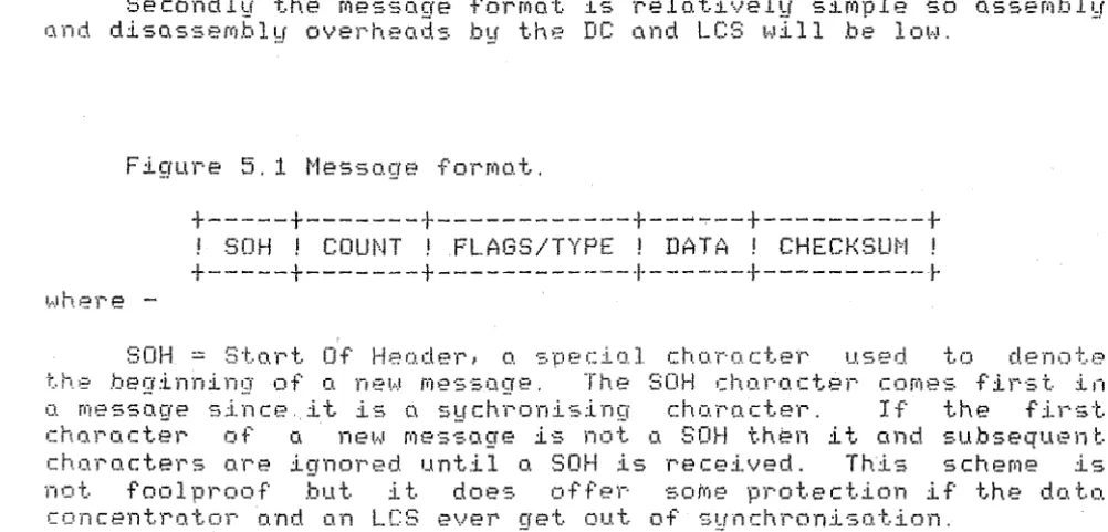
Figure 5.1 Message format.
+---+---+---+--~~--+---+
! SOH ! COUNT ! FLAGS/TYPE ! DATA ! CHECKSUM !
+---+---+---+---+---~
where
-SOH
=
Start Of Header, a special character used to denote the beginning of a new message. The SOH character comes first in a message since.it is a sychronlsing character. If the first character of a new message is not a SOH th~n i t and subsequent characters are ignored until a SOH is received. T~is scheme is not foolproof but i t does offer soMe protection if the data concentrator and an LCS ever get out of synchronisation.COUNT
=
A count of the number of 8-bit bytes in the message, from SOH to the last data byte inclusive. The COUNT byte follows logically in the message since, once the valid start of new message occurs the receiving station must know how many bytes will follow.The incoming bytes of a message are counted by the receiver so i t knows when the message is finished and a new one is expected.
[image:29.600.45.546.259.499.2]tv!ESS?iGE FORt·,1ATS PAGE 25
FLAGS/TYPE
=
the following tableFLAGS/TYPE byte. Bits are numbered
i~ a bit map of the
with 0 being the least
si.,;:1nificant.
Bit Funct.ion
7 If message direction is LCS -) DC then
0
=
Tx loop to LCS is working1
=
IX loop to LCS not workingIf message direction is DC -) LCS then
0
=
Message is a response to a RELOAD message.<RACK - Reload Acknowledge)
5,6 Reserved for future use.
0-4 Specify a unique message type. for example
ACK .. SET HEt·IOR'l .
DAT{-1 == Up to 4~~
message tyoe. The
message types, e.g. can be omitted.
.bqtes of :L·nforrno.t:Lon, spec.:L·!':Lc to tb.e
aata field may not be'needed for some
control messages or
READ
MEMORY, and soThere are no restrictions on the bit patterns allowed
in these 42 bytes since, unlike some protocols, the data is
totally transparent. The limit of 42 bytes is imposed by
-2. The fo.ct tho.t doto. for loco.d.in9 into LCS p·1emor·v formatted on disk in blocks of this size.
CHECKSUM
=
the byte containing the unsigned arithmeticsum of all the preceding bytes in this message i.e. all
bytes from SOH to the last byte of data, inclusive. In some
byte count oriented protocols (e.g DDCMP C4J) the checksum
is computed as a 16-bit total but in this protocol only an
8-bit checksum is used since it is easier for the LCS's to
perform single, rather than double byte additions.
Another reason for limiting the checksum to 8-bits is
that the lenath of the control messaae becomes four bqtes, a
convenient size when it is realised ihat the core all~cation
routines of the RSX-118 operating system allocate memory in
PAGE 26
CHAPTER 6
PROTOCOL DEFINITION
This chapter presents the definition of the protocol for the Traffic Control network.
6. 1 QUEUEING OF MESSAGES
A message transmitted from the DC to an LCS may have originated in the HOST; which will be the case under normal
circumstances, or in the DC if the HOST is out of action.
A aueue of messaaes waitina to be transmitted to each LCS is
maintai~ed in the ~C. The -queues are organised according to
message prio0ity, this priority being determined by the message source. See Chapter 7 for more details of the implementation.
When a message is to be added to a transmission queue in the DC, several checks are made of the link.
(i) Rx loop - The Rx current loop carries the data signal from the LCS to the DC. If this loop is broken then the DC cannot receive messages f~6m the LCS.
Cii) Tx loon - The Tx current loop carries the data sianal from the
be
to the LCS. If this loop is broken then the-LCS will not receive any message sent by the DC. The DC cannot check the status directly, but instead i t relies on the information contained in bit 7 of the FLAGS/TYPE byte, of messages from the LCS.<iii) Link closed - If Section 6.3) then no LCS.
the link closed flag is set (see messages can be sent from the DC to the
Start
l
Rx loop
No
broken?---~
~
r---'---'Ye-=5 ______Tx
loop
broken
.P
~j
f---'"''--'-e-=-5
---/ink closed
.?Is the message o
Is .Me
SET /V!EMaf(Y
~;vith__
ve.s _ _,_the
RACK b;t
set
queu~ emp~'!?
D
equeue message
!ij
!.sth:re o
.
message
.
t
th I
d
.rt.h
be;ng transmitt-ed
o e 1eo or e
queue ond
d!~;cordReturn
1.
IJi?k down '
status
to
the
source
of' the
message
just
dequeued
·Insert
lessoge into
queue according to
/ts pr/orit!J
Oi7
this
link
!lj
Set
lnessage
in
progress'
flo.9
l Tronsm;'t
j
message
Stort the timer
PAGE 27
No
Insert
messoge
into
Ves
. - queue according to
its prior/t.!:!
Handling b!J L C S
dr/ver of
o messo3e
from
PROTOCOL DEFINITION P?it3E 28
conditions.
[image:33.597.57.563.67.786.2]If the link passes the checks then the message is inserted in the queue according to its priority.
Figure 6. 1 shows the decisions made before a message is to
be added to a transmission queue.
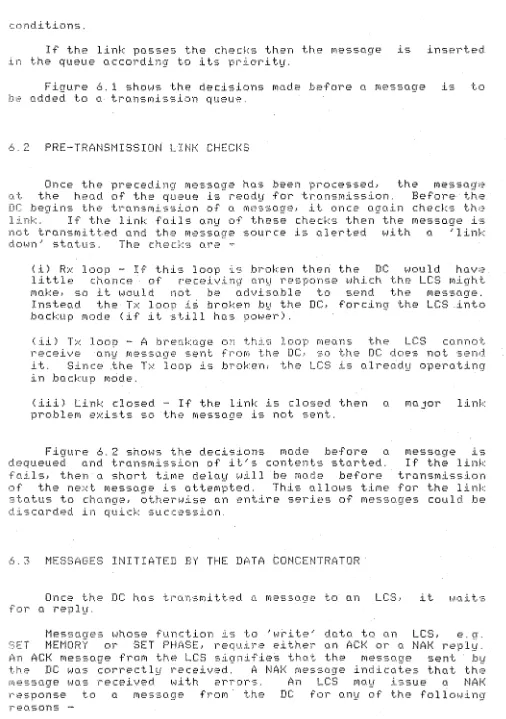
t. .. 2 PRE- TFANSI·1I SS I ON LI Nl< CHECI<f3
Once the preceding message has been processed, the message at the head of the queue is ready for transmission. Before the DC beains the transmission of a message1 i t once again checks th·~
link. If the link fails any of these checks then the message is not transmitted and the message source is alerted with a 'link down' status. The checks are ~
(i) Rx loop - If this loop is broken then the DC would have little chance of receiving any response which the LCS might make1 so i t would not h~ advisable to send the message.
Instead the Tx loop i~ broken by the DC1 forcing the LCS .into backup mode (if i t still has power).
(ii) Tx loop - A breakage on this loop means the LCS cannot receive any message sent from the DC, so the DC does not send it. Sine~ the Tx loop is broken. the LCS is already operating in bo.cku·p mode.
(iii) Link closed - If the link is closed then a major link problem e~ists so the message is not sent.
Figure 6.2 shows the decisions made before a messaae is dequeued and transmission of i t ' s contents started. If th~ link fails, then a short time delay will be made before transmission of the next message is attempted. This allows time for the link status to change, otherwise an entire series of messages could be
discarded in quick succession.
6.3 MESSAGES INITIATED BY THE DATA CONCENTRATOR
Once the DC has transmitted a message to an LCS, for a repl\:.f.
i t hi 0. :L t ·:=.
-F(J. G.2
Start
j
Rx loop
broken
P
No
8reak -the
7X loop
I
r- ····---
Yes7X
Iloop
---~--broken p
Return link down
PAGE 29
1
~J
status to the
---~~- ---~----Link closed?
rnessoge source
1/1/a/t o
short
while
y
Try
to send
next messo.3e
Cornmunicotion link te.sting before
me.sso.ge
tran.smi.ss1on
T
Tronsrn/t
y
S-tart
the
PROTOCOL DEFINITION PAGE 30
1. Checksum Error - The checksum computed b~ the LCS, which
received the message, did not match the checksum which the DC computed and transmitted.
2. Buffer Unavailable - A buffer was not available in the LCS to
store the incoming message.
~. Overrun - The receivinG hardware in the line driver and/or
LCS, or the LCS softwa~e, was not able to respond f~st enough
to incoming bytes and so one or more bytes of the message
\.\tere 1 o·::. t.
4. Header Error - The header section of a message contained
illegal values. For example, an invalid function code or ~
message length which exceeded the allowable limit. This
provides protection against errors such as the DC or an LCS
writing the wrong value in a header field.
Messages whose function is to 'read' data from an LCS, e.g.
COUNTER SERVICING or READ MEMORY, require slightly different
responses. If the message is received correctly by the LCS then
the response message contains the data requested. If the message
is received incorrectly tHen a NAK message is issued by the LCS.
To detect a lack of response from the LCS, a timer is
started in the DC immediately after the last byte of the messag~
has been transmitted. One timer will exist for each message
currently in p~ogress. When a response is received from the LCS
the timer is reset. If, however, the timer is not reset before
it exceeds a tritical value then the message is said to have
'timed out'. I have defined the critical value to be 3 seconds.
Thi·::. \,.Jill give ample· t.:L'r,.,e for· o. respon=-e to be received.
If the DC receives a NAK response. an incorrect data
me·::. sage.. or· time·::. out.. then it hti 11 r'etl~o.n:.mi t th>::· me-::.so.·~re.
There is a defined limit of 3 on the number of times a message
can be transmitted and when this limit is ·exceeded the message is
aborted and the message source is alerted. It is up to the
source to decide what action to take if, say, a SET PHASE command
has to be aborted. An attempt is then made to send the next
message queued to this LCS.
If 5 consecutive messaaes to an LCS are aborted then the
link to that LCS Will b~ closed, by setting the 'link ~losed'
flag. since a serious problem must exist. The closure means that
no messages will be sent from the DC to the LCS though the LCS is
still free to transmit to the DC. A diagnostic message 1s sent
to the system log and the link can only be reopened by operator
intervention or a RELOAD message from the LCS (see startup
notes.).
If a message receives, as reply, an ACK or a correct data
message then the source of the original message is notified of
PROTOCOL DEFINITION PAGE 31
I - t 1
b.~.~ EXAMPLES OF MESSAGES INITIATED BY THE DC
The message exchange examples on the following pages. between the DC and an LCS, use the notation below.
By arbitraru convention the DC is the left hand side of the diagram while an-LCS is on the right.
---)
Message sent. received correctly.---/---)
Message sent, received with errors.PROTOCOL DEFINITION PAGE 32
6.3.2 NORMAL 'READ'
'read' message
---)
data received
(---6.3.3 NORMAL 'WRITE'
'write~ message
---~---)
ACK
(---PROTOCOL DEFINITION PAGE 33
6. ~ a 'READ' OR 'WRITE' WITH ERRORS
me·:; ::.o.qe
---/----)
NAK
<---~---~---RETI-'Y 1 "reo.d" (or' 'I,,J'f'i te')
---)
do. to. (or· ACK)
<----!---h~E TF~Y2
rrre~.so.ge
---)
do. to. (or ACK)
(---6.3.5 MESSAGE ABORTED
PROTOCOL DEFINITION
RETRY MAX message
---/---)
NAK
(---Message has failed MAX times so the message is aborted.
<MAX is defined
io
be 3)message received in error.
PROTOCOL DEFINITION
6 3. 6 TIMEOUT OF 'READ' OR 'WRITE' MESSAGE
PAGE ~=
~~·-'
A timeout ma~ be caused in the DC by an~ of the following
Situations and will be treated the some as a NAK received from an
LC:::.
6.3.6. 1 LCS does not receive
message-I I ...
---;;---;
LCS does not receive
message e.g because of
power failure, hardware
or software fault.
Message received in error, NAK received in error
---/---)
message received
(---/---t··Jr:~f< re cei·v·ed
PROTOCOL DEFINITION PAGE 7L
·-IW
6.3.6.3 ACK or data received in
error---)
message received
correctly.
ACK ol~
d.o.to. response
·' '
~---~---AC::!-<: or d.o.to.
received in error.
6.3.6.4 NAK not
received---/---)
message received
in error'.
NAJ<
<---11---NAK not received
e. Q. because of R;,~
PROTOCOL DEFINITION
6.3.6.5 ACK or data not
received---)
ACK or
do.ta !'IS'S'pDn·;:.t?
<---11---Not teceived e.g.
because of Rx loop fault.
message received
cnr-re ct.l ~~.
PROTOCOL DEFINITION
6.3.7 LINK CLOSED
Message 1
---/---)
Message retried MAX tiMes.
NAK
<---Message 1 aborted
Message 2
Message retried MAX times.
NAK
(---Message 2 aborted
message N
PROTOCOL DEFINITION PAGE 39
---/---)
rne:::.·:;c:Ge retried.
t· .. l ~~ >< t. i m e s .
{---Message N aborted.
Link clo·;ed d.u.e to N con':.•-ecu.tive
PROTOCOL DEFINITION PAGE 40
6.4 MESSAGES INITIATED BY THE LCSs
Most of the messages initiated b~ the LCSs will be sent soontaneously, to report a change in the status of either the LCS, or the local controller i t is monitoring. These messaaes contain information which is useful but not critical to the operation of the traffic system.
If the messaae is received correctly by the DC then the information in ihe message will be passed to the HOST, which is monitoring the status of all the LCS's and the local controllers. The message will also be copied and sent to the mimic display.
If the DC receives the messaae with errors or has no available buffer space then the mess~ge is ignored entirely.
The LCSs never expect a reply of any description from the DC in response to messages which they initiate. One exception to this rule is the RELOAD message, which is illustrated below.
~.5 RESTARTING A LINK
Loss of power to an LCS causes the random access memoru to be corrupted and the local controller to go into IVA mode. it is important to be able to reload the RAM, and get the LCS reconnected ~n the network as soon as possible once the power is restored. This is the startup process.
It makes sense to let the LCS rather than the DC initiate and control the startup ptocess on a link since
-1. Once the DC knows the LCS is 'down' i t does not have to waste time repeatedly trying to restart the link. It waits instead until the LCS is functioning and sends a RELOAD message.
2. Only those LCS's which require restarting at any one time will get attention. If the DC initiated the startup i t would have to poll all the LCS's to find those needing a reload. This process could become very time consuming and complicated.
Th~ following is a description of the startup process.
1. The LCS has its power restored and code in the ROM is activated causing, among other things. a RELOAD message to be sent to the DC. At this stage the DC may or may not be
powered up but the LCS sends its message regardless.
PPOTOCOL DEFINITION PAGE 41
~hen the DC will send the first of a series of message~ to
r2load the LCS's memory the only ~ime an unsolicited
message is acknowledged by the DC. The LCS will repeat the
RELOAD message at 15 second intervals until a successful SET
MEMORY message is received.
3. The high priority SET MEMORY message sent to the LCS will
have the RACK <Reload Acknowledge) bit in the flags byte set
to indicate to the LCS that the RELOAD message was correctly
received by the DC. Any message received by the LCS, while
it is trying to restart the link with the DC, will be ignored
if the RACK bit is not set.
4. The LCS acknokrledges the SET HEI'JDRY mes·::.o.ge t·J:Lth on ACK, :Lf
it '··'-'O s 1~e ceived correct 1 hi', ot.hen.Jise n NAK. If the SET
l·IE!··JOF:Y me·::.·?.CP~fe fo.il·.c:. en' 'LUne·.:::. out.' 3 t.imt:··;:. then the DC
discards the SET MEMORY message and waits for the LCS to
issue the next RELOAD message. When the ACK is received the
DC declares the link open. if i t wa~ previously closed, by
clearing the 'llnk closed' flag. The DC can then proceed to
PROTOCOL DEFINITION PAGE 42
6.5. 1 RESTART EXAMPLES
The followina are examoles of different situations which can
arise during-the normai startup of a link to an LCS.
o.5. 1.1 Normal startup-DC
RELOAD
(---Start timer.
Receive RELOAD
message.
SET MEMORY
message with RACK
bit set.
---)
Stop timer.
ACK
r
~---The DC now proceeds to RELOAD the remainder of the LCS's memarv,
PROTOCOL DEFINITION PAGE 43
6.~. 1.2 RELOAD message
falls-DC
bQ§
RELOAD
(---/---Start t~mer.
DC ignores unsolicited
mes~age with errors.
15 seconds
v
Timer expires.
Send another RELOAD. RELOAD
(---Start timer.
receive RELOAD
message.
PROTOCOL DEFINITION PAGE 44
6.5. 1.3 DC does not receive the ACK message
RELOAD
~
~---Start timer.
Receive RELOAD message.
SET MEMORY
message with RACK bit set.
---)
Stop timer.
ACK message
(---/---Start timer. ACK received with
errors or not at all.
15 seconds.
v
Timer expires. Send RELOAD again. RELOAD
(---PROTOCOL DEFINITION PAGE 45
Pf.iGE 46
CHAPTER 7
P R 0 T 0 CD L I tvJ P L E ~··IE NT AT I 0 f-.1
This chanter describes the implementation of
handling pr~tocol in the data concentrator,
the mes·:;o.c1e !-.ll t h 1 n
u;
•.?constraints of the RSX-118 Executive.
The code to implement the protocol is contained in . a
standard RSX-118 I/0 driver called the LCS driver, which is
linked into the Executive at system generation time.
7. 1 AN OVERVIEW OF THE R~X-11S I/0 PROCESS
An I/0 cl.r·i'v'>?r· call·:::. o.nd i·:. colled by the E:.\:ecu.t;L·.,..·e t.•:•
service an e~ternal I/0 device or devices.
It is usual, in RSX-118, for all I/0 devices to be declared
to the Executive via a series of tables. The tables contain the
static attributes of the devices. such as allowable functions an•f
interrupt addresses, as well as dynamic device attributes, such
as controller status and lists of pending I/Os.
When a task wishes to make an I/0 request i t issues a QIO$
(Queue I/0) system directive to the Executive. The Executive
performs validity checks on the QIO$ parameters and if these
checks are successful then the Executive generates a data
structure called on I/0 packet, which is inserted into a device
specific queue of I/0 packets.
The Executive also notifies the LCS driver that an I/0
oacket has been queued to the device. From information contained
in the I/0 packet the driver can initiate the I/0 operation and
then continue with other activities. At a later stage when the
previously issued I/0 operation interrupts, the driver is called
to process the interrupt.
Upon completion of processing for an I/0 request, the driver
calls the $IODON (I/0 Done> procedure which returns status
information, on the completed I/O, to the task which issued the
I/O reque·:st.
For more details of RSX~11S see [5] and [6J. Although these
PROTOCOL IMPLEMENTATION PAGE 47
7.2 HANDLING MESSAGES TO LCSs
Thi=· ·~.ect.ion de·::.c·,~;L.be·.::. hoh' me=:.:::.oges t.::r .be sent to LCS·::. nl~•?
handled. The handling process is represented diagrammat~cally in
f i 'J' u )-· l=:• 7 . 1 .
It was desirable. in this implementation, to have a queue of
I/0 r0auests for each LCS. This nllows full use to be made of
the communication links and the DZ11 multiplexors. since
transmission of messages from the data concentrator to different
LCSs can then be overlapped.
The initial approach
a separate I/0 device
soon become aopnrent that
was to consider eath of the 128 LCSs as
which is declared to the Executiv~. It
this ooprooch was infeasible since the
~'lftt=~r ;.1uch. 'lhou.crb.t, o. f!)ethoc1. lcc.l(•.·:;. dE~\'is·~'d. for .b~~rpnssl.ng· the mer.-,or·v r•?quil-·err,ent·s pi··o.bl•:::-m. In~:;;ti.:•o.d of hoving 128 LC:3 device·;. declo.r·ed. tc:.; the ·:::.~,;.f·:;t.em, o. ·p·:;:.;?u.d.:~··-deo...,:Lce. co11.r::.!d .l.CO: t...to.:::.
declared. Any task wishing to send a messoge to an LCS queues
the LCS number, messoae size and messaae address to device LCO:,
via the QIO$ directiv;. This causes a~ I/0 packet to be inse~ted
in the queue of I/0 packets for device LCO: and the LCS driver
notifLc:•d of this in~.er·tion. BC\·:::.ed on infor·fitot:i(J'f: in the I/0 po.cket, thE• t_c:::::: dri\1er t..-Jlll then r'e1ink ttte ·p(::>.cke·i .. into o.n internal. priority based queue. one of which exists for each LCS.
By bypassing the normal RSX-118
pseudo-device. C\ ·::.epo.r'o.te queue of
therefore be maintained with acceptuble
device approach with a
r·equest·::. fol~ each LCS con memory requirements.
Once it is time for o message to be transmitted~ the message
is accessed via the size and address stored in the I/0 packet,
and is transmitted a byte at a time to the LCS concerned.
A
re~ly is then awaited from the LCS.
7.3 HANDLING MESSAGES FROM LCSs
This section describes how messages received
dealt with by the LCS driver. The process
diagrammotically in figure 7.2.
frorll LCSs al~e
i·"'· r·epr·e·;ented
Messages arrive from LCSs a byte at a time, the bytes being
stored directly into a DZ11's silo, which con hold up to 64 bytes
of doto..
The~e are three different options available for clearing a silo
f:J.
71
QIO$
System
Directive
from
'transaction
monoger'
or other task
1i1Data
Concentrator
I/0 pocket:
queue
for LC(!)
link bypriorit!J
LCSl
LCS2
Unlink
LCS/28
LCS
Driver
/2 8 Priorit!J linked
FIFOs maintained
internal
(!J
b!:f L CS
driver
._______ _ _,_ Trona mit
to
L CS
L _ _ _ _ _ _ _ ______,_
.._____ _ _ _ _ _ _ _ _ _
...,_at ISR priorit!J
Handling
by
LCS dr/ver of
me.s.soses
directed to LCS
s
r
LCS I LCS2 LCS/28 ~
PAGE 49
Messoge.s
transmitted
from LCSs
~ ~---~
Rece1ver
buFfers
picked dynamically
at
IS/?
priority
(sol/cited)
I
0
I
I
-{J
Messo.9es
inserted
ot
ISR
priority
FIFO queue
of
rece;i/ed
messQges
Me:ssqges .
unlinked
at Fork level
(low pr/orit.!J)
QIO$
system
directive from
· transoct;on
managpr
l
I/O pocket
queue
f:::;r
LCJ
I
lest messose i!Jpe
L[J
(unso/ic;ted)
Associated
.message with
previous(!;
rece/ved
9
I O$
and
return
messoqeas
..;1data
U.se message as return
data for the QIO$ directive
. ;