COSC 460 Honours Project Department of Computer Science University of Canterbury
Report on
MacDiammer-Design & Implementation
Supervisor : Dr. N. Churcher
CC({J)W'll'JEW"Jr~
SECTION 1 INTRODUCTION 1
SECTION 2 BACKGROUND TO PROBLEM 2
2.1 General Techniques Surveyed and Related Work
2
2.2 Entity-Relationship Modelling
2
SECTION 3 MACDIAMMER DESIGN 4
3.1 Diagrammer at the Conceptual level
4
3.2 Overall Design
4
3.2.1 'Ideal' features
4
3.2.2 Aesthetic Requirements, Notations and Effects
5
3.2.3 What it does 10
3.3 Semantics of Diagram
14
SECTION 4 MACDIAMMER IMPLEMENTATION 15
4.1 Choice of Software Tools
16
4.2 Diagrammer Construction
16
4.2.1 User Interface
16
4.2.2 Screen Format
17
4.2.3 Entity-Relationship Objects Placement
20
4.3 Data Structures
20
4.3.1 Linked List
20
4.3.2 Records
21
4.3.3 Files
22
4.4 Validation and Checking
25
SECTION 5 RESULTS AND FUTURE GOALS 26
5.1 Overview of Results
26
5.1.1 Comparisons with equivalent diagrammers
26
5.2 Problems and Limitations
26
5.3 Goals
28
SECTION 6 CONCLUSION 30
Acknowledgements & References 31
MacDiammer Report I SECTION 1 INTRODUCTION
Data base design is without doubt a complex, challenging and creative process. On the other hand, it can be a tedious and error-prone process as well. The first complexity comes from the fact that high level of interaction between people is involved in establishing the users' requirements. Inadequate communication skills on either the . analysts part or the users often lead to errors and consequently, poor data base design. In the past, this problem has been further accentuated by the lack of proper design tools to aid the analysts or designers. This later problem has been overcome to a great extent by design tools consisting of various automated diagrammers.
The aim of the project is to design and implement an entity-relationship diagrammer, MacDiammer as a graphical design tool. The diagrammer can be used as a stand alone application or as part of an integrated set of design tools, say with procedures diagrammer. In SECTION 3, I shall talk about the issues involved in the design of a diagrammer and how it differs from other equivalent diagrammers. SECTION 4 covers what has been implemented. An overview of the results achieved, the problems encountered and future goals will be presented in SECTION 5.
The reason for designing an entity-relationship diagrammer, its relations to entity modelling, problems associated with data base design and graphical tools for data modelling in general will be discussed in SECTION 2.
MacDiammer Report 2 SECTION 2 BACKGROUND TO PROBLEM
2.1 General Techniques Surveyed and Related Work
In the logical data base design process, one technique used in requirements specification is the forms-based approach, example can be found in [Shu83]. This is a better technique than holding informal interviews between analysts and users. More recently, another technique that is increasing in popularity is CAD/CAP(Coniputer Aided Design and Programming) technique. This technique together with stepwise software methodologies like information engineering introduced through Martin[Martin86] has resulted in commercial tools like lEW (Information Engineering Workbench), and the BLUES data modeller.
lEW is the more impressive one, it incorporates an expert system (a knowledge base with over 1000 prolog rules) as a knowledge coordinator with different types of diagrammers ranging from decomposition diagrammer to data flow diagrammer. At a smaller scale is the BLUES 60 data modeller, one of 8 different types of diagrarnmers.
Earlier experiments have produced a graphics-based system using Chen's I
Diamond notations[Chan80] and IN COD [Atzeni83] as part of design tools. 2. 2 Entity-Relationship Modelling
Among these diagrarnmers, one that is regarded as the most important tool is the entity-relationship diagrammer.
In fact, entity modelling of the real world of an enterprise has been acknowledged to play an important role in simplifying the data base design process at the conceptual level. The significance of an entity-relationship approach to data base design is detailed by Chen [Chen76, Chen77] and Martin [Martin86].
MacDiammer Report
3
modelling. In this approach, any real-word things of interest with information to be stored are represented by entities, associations between entities are described by · relationships, and finally attributes are used to define the properties of entities[Martin85].
Based on this fact, a well-formed entity-relationship diagram offers the users a clear picture of how a data base for an organisation should be formulated.
The function of an entity-relationship diagrammer is two-fold, besides drawing of E-R diagrams, it allows a user to create and maintain a Entity Relationship ModeC ie by capturing data about entities, relationships and attributes. This by far is a more desirable tool than a pure documentations tool which could not show the structure of a model graphically.
MacDiammer Report 4 SECTION 3 MACDIAMMER DESIGN
3.1 Diagrammer at the Conceptual level
An E-R diagrammer functions at the conceptual level, thus in line with the specifications of other conceptual schemas[Nijssen87, Chen77], the entity-relationship diagrammer at this high-level:
1 should be independent of the underlying physical data base design[SECTION 2, 2.2] ie whether the final data base turns out to be a network, hierarchical, relational or binary data base, is irrelevant to the diagrammer. The E-R diagrammer does not at the conceptual level try to resolve any ambiguity in the data model to suit any particular physical data base defmition.
2 will not perform any norn1alisation of the data model. This follows from 1 above plus the information engineering concept which shows that a fully normalised data model is developed at the Business Analysis stage after an entity model has been built in the Information Strategy Planning stage[Martin86]. Also norn1alisation is the job of a data modelling tool which will be part of the integrated tool package.
3.2 Overall Design
3.2.1 'Ideal' features
Ideally an entity-relationship diagrammer should be able to :
1. collect all the necessary requirements about entities, relationships and attributes from the user.
2. generate automatically the layout of an E-R diagram after all relevant data has been obtained.
3. provide a set of drawing functions(modes) on the screen to let the usercreates and manipulates his/her own E-R diagram directly on the screen.
4. support a data dictionary to store the details of the components of the model.
5. saving and loading of a data model.
MacDiammer Report
5
In addition, the diagramrner should be user-friendly and simple to use.
One main problem with some of the tools currently available is that they are far too sophisticated for an uninitiated user and would require the user taking some time to leam how to use the tool effectively and efficiently. With this in mind, the design for this project focus on providing a friendly environment such that there is user involvement in all stages in the data model development process and the users need only acquire minimal graphics knowledge although they would be expected to have had some prior knowledge of entity-relationship model.
Among these 6 features, the Automatic generation of entity-relationship diagram will not be implemented in the diagrammer for the reason that time constraint does not make this automatic generation possible which is a project by itself. Entity relationship diagrams layout problem can be formulated as a quadratic assignment problem, which has been proven to be an NP-complete problem [Tamassia83]. Algorithm for generating entity-relationship diagram was the main topic of Peter Bromley's Honours Project in 1985, ie building a diagrammer for the EXSYS™ data model[Bromley85]. His diagrammer is a documentation tool whereas MacDiamrner is intended to be a design tool, therefore users control are desirable such that they can pe1form on-screen manipulation of the E-R diagram.
3.2.2
Aesthetic Requirements, Notations and Effects
Before explaining the detail designs for the rest of the features outlined previously, it is essential to define graphical notations for the objects on the entity-relationship diagrams.
The aesthetic requirements for an E-R diagram are very important, because a clear picture will give an easy-to-understand conceptual description of the data involved to the users. Therefore, the design will strive to :
minimise the number of relation lines crossing reduce the potential of objects crowdedness
MacDiammer Report 6 Notations
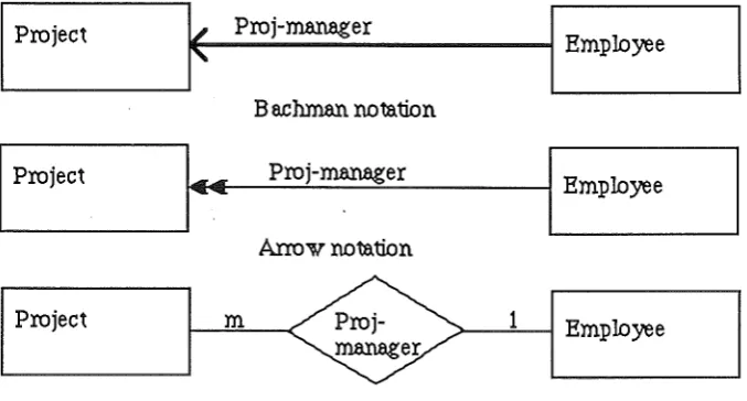
A few standard entity-relationship notations shown below : Bachman notation
Arrow notation Chen's diamond Crowfoot notation
were studied to find one that is adequate and reasonably simple to be implemented. Examples of these notations are shown below.
I
Projectf
Proj-m.anagerI
Employee
B e.ch.man notation
I
ProjectI··
Proj-m.anagerI
EmployeeArrow notation
I
Project<€>
m 1
I
Employee m.anager
Chen's Diamond notation
Fig 3.1 Examples of E-R notations
Each of these notations has its own merits but some lacking in certain aspects. For instance Bachman notations are limited and has no specific way to draw functional dependencies whilst arrow notation contains directional connotations. Chen's diamond is a popular notation, but it is felt that using diamond to represent relationship will create confusion with the flow-chart notation of using diamond to denote decision box.
Crowfoot notation tries to distinguish between all different kinds of association*, making it too cumbersome at times. Nevertheless, it is used widely in a lot of modellers and this eliminates the problem that users may feel uncomfortable if faced with notations that are unfamiliar to them.
[image:8.595.110.449.276.458.2]MacDiammer Report 7
For this matter, the notations adopted are those of the Crowfoot notation but simplified, ie no vertical/horizontal stroke will be drawn across a link to indicate a one to one relationship. An example of this slightly modified version is shown in Fig 3.2.
Entity A
Entity B
One to One Relationship
Entity A
4
Entity B
One to Many Relationship
Entity A
~
4
Entity B
Many to Many Relationship
Fig 3.2
Notations to be Used in MacDiammer
Other representations of entity and relationship were examined, such as the NIAM conceptual schema[Verheijen82], which uses ovals for entities, and rectangular boxes to represent relationships, and the enhanced conceptual structure derivation [Maciaszek86] which has a new set of notations of its own. They are interesting variations but would require more learning time on the user's part, as they are not as easily understood as Crowfoot notations at first glance. Another problem with NIAM standard would probably be the added complexity in implementation.
[image:9.595.127.477.148.433.2]MacDiammer Report 8 Ternary relationships, functional dependencies will not be considered as it is beyond the scope of the project to include all types of associations. The graphical design of the diagrammer can be extended to display both ternary relationships and functional dependencies without too much difficulty. However, in terms of data model storage, it is likely that ternary relationships will increase the complexity of such storage design more than that of recording functional dependencies.
Entity shall be denoted by a fixed size rectangle, with enough space to display the longest entity name which means able to wrap around the name to the next line inside the box. The main reason for not having variable size rectangle is that there is no real advantage in doing so except complicating the implementation.
Generic Relationships
Another design problem arises when there exists more than 1 relationship between 2 entities. The questions is :
Should both relationships be represented individually ? And what is the effect on the aesthetic value of the diagram ?
If the answer is yes, then this would reduce the aesthetic value of the diagram due to the additional relationship line(which can consist of more than lline segments) and relationship names.And in the meantime, increasing the chances of line crossing and objects clustering. Even if a proper algorithm for E-R diagram layout is included, the situation will worsen if more relationships are defined between the same entities*.
One way to deal with this problem is writing the number of relationships that exist between 2 entities on the relationship line. This method is justified for a machine that does not have excellent graphics facilities. Using Macintosh graphics package, a better solution is expected.
MacDiammer Report 9
To overcome this problem, a 'level of views' concept and 'generic relationship' type shall be introduced. This means defining 2 levels of operations in the entity-relationship drawing, ie a top-level view and a zoom-level view. At the top-level, the graphical representations of relationships now consist of :
For 1 relationship only between 2 entities : the usual notations apply
For more than 1 relationship between 2 same entities :
a generic relationship line will be drawn, without any relationship name.
To distinguish the generic one from the others, it shall be drawn thicker(denoting more than 1 relationship), together with a small arrow enclosed in a rectangle tagged to the line (above or below the line shall be determined by the flow of the relationships) indicating the flow of connection from 1 entity to another plus the usual crowfoot notations, if applicable. The generic relationship concept in turns necessitates the use of zooming facility so that the user is able to see in detail the relationships between 2 entities. Fig 3.3 illustrates how the level of views concept works.
Top-level view (includes generic relatiol'l3hips)
l
Zoom-level view (individual relatiol'l3hips)
1
Detailed descriptiol'\3 of relatiol'l3hips
[image:11.598.78.493.275.808.2]MacDiammer Report I 0
3.2.3
What it doesCollecting user's requirements
The design for this is to be able to accept input from users consisting of the description of entities, relationships and attributes only. At this conceptual level, the actual values for the attributes are not a concern to the diagrammer, but rather this function is relegated to other design tools.
Providing a set of drawing functions
As I have mentioned before, the approach to entity-relationship drawing in this project is significantly different from Peter Bromley's diagrammer [Bromley85]. The diagrammer proposed here allows the user to select where to place the entity box, only the relationship lines are generated by the diagrammer whenever the user defmes a valid relationship between any 2 entities. In a way, the diagrammer offers user's flexibility, high interactiveness but at the expense that the user can choose to.abuse the diagram if wishes eg drawing entity boxes on top 'of each other.
A user then is likely to spend a lot of time making changes to the diagram drawn through the use of the mouse. Possible changes that a user may want to make are :
i) drawing a new entity box
ii) adding a new relationship between any 2 entities
iii) zooming in to examine or edit the description of an entity, relationship or attribute
iv) deleting an existing entity, relationship. or attribute v) moving entity box to a new position
i)- v) represents the 5 drawing modes that the users can use in drawing the E-R diagram. There are 2 ways that such features can be made available to the user :
pull-down menus palette of icons
MacDiammer Report 11
Drawing applications such as MacPaint and MacDraw rely heavily on such idea
It is a more natural way of drawing since the user can see at once on the screen the types of drawing mode available and switches from 1 drawing mode to another simply by clicking on the required icon.
In addition, different cursors shall be defined for different types of drawing mode, to remind user about the current mode he/she has selected.
For feature iii), see Fig 3.3. By allowing users to delete an entity or relationship, feature iv) may at times be used accidentally. It was then decided that the design should be able to prevent such mishaps, which cannot be undone. This involves getting the confirmation from the user before actual deletion takes place.
It is decided that deletion of relationship should be restricted to one at a time. The same rule applies to deleting an entity and an attribute. It is felt that deleting multiple items at one time is a potential trap for unint~ntional errors even with getting user's confirmation before actual deletion. This means then generic relationships are handled by using the level of views concept [refer Fig 3.3] to move to the zoom-level such that users may then delete relationships one at a time.
A question arises when deleting an entity, ie should any relationships that this entity is involved in be deleted as well and what about the attributes that describe this entity. Considerable thoughts on this question came up with a solution of deleting all relationships that the entity is involved in and those attributes that described the entity. This brings to mind the question of how attributes are associated with entities. The association chosen reflects the reasonings behind the solution.
Fig 3.4
MacDiammer Report 12
~-E-n_ti_~----~---~~~--A-ttrt--'b_u_re--~
Attribures describe a
particular enti~~-En_u_·~--~~---~~--A-ttrt-·b_u_re~
Many entities may be described by many attribures
(ie no ownership concept)2 approaches to associate entity and attribute
The advantage in the second approach is that attributes may describe any number of entities and attributes can be moved from 1 entity to another. This means that users need not enter same description for an attribute but can use one attribute for different entities. This amounts to saving some time and efforts on the the users behalf. The disadvantage lies in the possibility of dangling attributes which may occur when an entity is deleted and some attributes (of which their only functions are to describe this particular entity) still exist as part of the data model even though they no longer serve any purposes. An example is the BLUES 60 data rnodeller which shows that when an entity is deleted, attributes that described it still remain because they may have been used to describe other entities.
Considering that the time saved in entering information is minimal (given the simple-to-use interface) compare to the dangling attribute problem which is highly undesirable, it is decided that the approach taken in this design will be the one to many association such that definitions of attributes are only possible through identifying an entity first (ie the owner-entity)[refer SECTION 4, 4.2.1]. This would mean that even though 2 attributes may have the same name but if they are owned by 2 different entities, then they are considered to be non-identical. This approach does carry the disadvantage of repeating attribute description but it justifies the reason for deleting all attributes to avoid the dangling attributes problem.
MacDiammer Report
I 3
having relationships that connect some entities to an entity that has been deleted. If the design has included functional dependencies than a more complicated deletion· mechanism will need to be considered. For this design, the solution suffices to do the deletion without unduly complicating the implementation later on.
Feature v) is limited to entity box only but not relationship lines for the reason that given the short time available, to do both will complicate the implementation of such diagrammer, instead I shall concentrate on the entity box.
Supporting a data dictionru:y for the components of the data model
The data dictionary shall be built up by capturing the information entered by the users. A comprehensive data dicitonary would have included cross-reference information to show for example, which resources are used by which programs etc,[Date83] but it is not the objective of the diagrammer to do so. Physically, the data dictionary for a particular data model will consist of a file of records, which can be records of entity, relationship and attribute [refer SECTION 4, 4.3].
Saving and Loading of a Data Model
It would be expected that the diagrammer should have the facility to store the data model being currently defined and retrieved later, if desired. Also users might want to load a different data model during the process of designing a data model. The diagrammer shall be designed to cope with these requirements. In addition, the diagrammer will always asked a user whether work done on a data model should be saved before exiting the system to protect against accidentally quitting from the system and losing any work done on the data model.
Printing of diagrams and Reports
MacDiammer Report 1 4
3.3 Semantics of Diagrams
It is relevant at this juncture to point out that the contents of a data model is inherently different from a text only document, or a diagram prepared using MacPaint or MacDraw, because all the objects in the data model carry meanings. Subsequently, in order to preserve the semantics of the diagram, the following are to be observed:
i) edit operations such as cut and paste do not apply. Eg, if the diagrammer. allows arbitrary cut and paste operation on entity box, then the data model will lose its integrity because an entity should be uniquely defined and therefore should only appear once in the E-R diagram.
ii) an entity name should be distinct from other entities, although they can have attributes with the same name.
MacDiammer Report 1 5
SECTION 4 MACDIAMMER IMPLEMENTATION
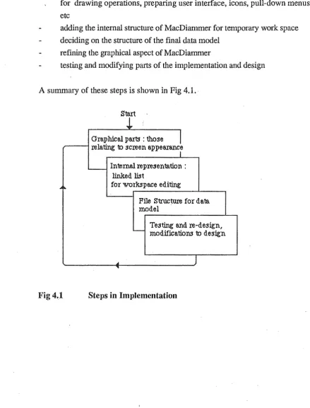
It was decided that the implementation should proceed in the manners described below while adhering to the design as closely as possible but occasionally it was found that changes to the design had to be made to suit the implementation.
implement the graphical part of MacDiammer, how the screen should appear for drawing operations, preparing user interface, icons, pull-down menus etc
adding the internal structure of MacDiammer for temporary work space deciding on the structure of the final data model
refining the graphical aspect of MacDiarnmer
testing and modifying parts of the implementation and design
A summary of these steps is shown in Fig 4.1. · Start
i
Graphical parts : those
I
relating to screen appea.rancr...__ Intemal representation : linked fut
...
for workspace editingFile Structure for data model
Testing and re-design,
-
modifications to designA
J
[image:17.595.58.498.233.811.2]"
MacDiammer Report 1 6
4.1
Choice of Software ToolsThe language chosen for implementation is Pascal. At the start of the design, 2 Pascal compilers were looked at, TML Pascal and LightSpeed Pascal. It was decided that LightSpeed Pascal provides a better environment for development of applications, in addition to being faster in compiling/execution. An additional tool is the ResEditl.ld4+, a resource editor.
ResEdit allows all the menus, windows, cursors, dialog boxes and dialog items specifications to be entered into a resource file which can then be used by the LightSpeed compiler. Without resource file, everything will need to be specified in detail inside the programs so that whatever is required can be drawn. Using resource file has certainly reduced the complexity of MacDiammer implementation.
4. 2 Diagrammer Construction
4.2.1
User InterfaceA window is used for the drawing of an E-R diagram. Each time a data model is created or loaded, a new window will be defined. Using window for drawing is consistent with the ideas in other Macintosh Applications. Also windows can be extended to more applications in future[ see SECTION 5,5.3].
Macintosh is well suited for diagramming purpose as it has excellent graphics capability, which are accessible via the Quickdraw routines calls. Therefore, Macintosh's Toolbox routines are used extensively to provide an easy-to-understand user interface.
Collection of entity, relationship and attribute description is carried out using dialog boxes. The text in the dialog boxes is self-explanatory for the user to know what is required. If it is mandatory for the users to enter an item, then the relevant field is highlighted. In the case of an error in the input, an error alert box will appear with the error message. Therefore, it is felt that implementing a help facility is not necessary.
Entity Dialog Box and Attribute Dialog Box
Attribute Dialog Box is nested within the Entity Dialog box. Consequently, attributes can only be created/modified/removed through the Entity Dialog box. The reason for this is to identify what attributes belong to which entity.
MacDiammer Report I 7 under a particular entity without opening up an attribute dialog box. Again, there are different ways to show the attributes. 2 of the alternatives considered are :
i) use of list window to display the attributes available.
ii) use of a data structure diagram using bubble charts [Martin85]
Method ii) has the capability to provide a clear picture of the data items including showing of the primary, secondary or concatenated keys. After some consideration, it was realised that drawing data structure diagram is not a priority job and it is better to concentrate all efforts on achieving the objective of this project.
So method i) is implemented inside the Entity Dialog box. In terms of implementation, both can be regarded to be equally difficult and complicated to do.
Default entity name is assumed but not so for attribute name.
'
Relationship Dialog Box
When a new relationship is defined, there may exist an inverse relationship. To cater for such requirement, an optional field is created for entering the reverse relationship name. It is not realistic to assume default relation name.
Attribute Dialog Box
The implementation has adopted the common practice in attribute name definition ie to attach as default-prefix, the entity name that owns it. The users can specify whether an attribute is a key or not. It is not the intention of the diagrammer to distinguish the issue of primary keys and foreign keys.
Examples of these dialog boxes can be found in Appendix II.
4.2.2
Screen FormatThe screen actually consists of 3 QuickDraw (graphics) ports : i) newport - palette of icons
ii) The Window- the main window for drawing E-R diagram
iii) Zoom Window- the zooming window for viewing relationships between 2 entities
MacDiammer Report 1 8 There are alternative ways to present the screen, such as putting the palettte of icons into TheWindow, but separating these 2 gives a better aesthetic view. Multiple · windows are not supported for reasons of integrity. Besides, it is not considered to be a must at this point because MacDiammer will initially be used as a stand-alone tool [SECTION 5, 5.3].
For the main drawing window, ii), the usual scroll bars and grow icon for window are supported. The scroll bars are important as it allows the users to see different parts of the E-R diagram when limited by the size of the Macintosh screen.
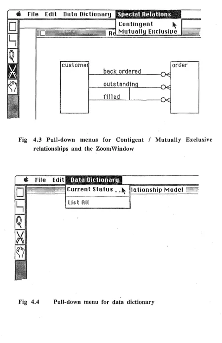
As with most Macintosh applications, the pull-down menu is implemented. The main use for the pull-down menus is for file operations, as illustrated in the menu bar shown in Fig 4.2. Another use is for specifying contingent or mutually exclusive relationships between 2 same entities(Fig 4.3) and checking the current ~tatus of the data dictionary (Fig 4.4), the former appearing only when a zooming window is in effect. Pull-down menus is favored over the Pop-up menus as it is the more conventional approach and given the time allowed for this project, it is simpler to implement pull-down menus. Disabled menu items indicate features that are not on top of the priority list of features to be implemented, but will be implemented if time permits.
Although MacDiammer does not allow cut, paste, undo operations, the edit menu exists to preserve the order of a usual menu bar. The system desk accessories are supported.
Edit
agN
Saue as ..
p
Quit ~Data l1ictionary
En tit Relationship Model
[image:20.598.69.532.490.787.2]MacDiammer Report 1 9
Gt
File Edit Data DictionaryR
custome
order
beck ordered
filled
Fig 4.3 Pull-down menus for Contigent
I
Mutually Exclusive relationships and tbe Zoom WindowFig 4.4
Current Status .• ~ lationship Model
U$tBH
[image:21.598.73.523.87.781.2]MacDiammer Report 2 0 4.2.3 Entity-Relationship Objects Placement
For connecting lines (relationships) between entities, a crude algorithm is used. The algorithm starts by determining whether to draw a line up or down from the first entity to the second one. After that , it determines either to draw a line to the right or left. So a relationship line is usually a combination of one vertical line and one horizontal line. However, depending on the difference in the offset of the second entity from the first, the relationship may consist of 1 vertical or 1 horizontal line only.
4. 3 Data Structures
4.3.1 Linked List
To implement the data structures for MacDiammer, it is necessary to look at the 2 stages in using MacDiammer :
i) working in the temporary work space, ie editing the E-R diagram and the entity, relationship, attdbute information before the user actually writes to a file
ii) the actual file contents for a particular data model
Unlike a text file where Macintosh provides a pre-defined text edit record for storing of text and other information, there is no facility in Macintosh data structures that support diagramming.
The factors that affect the choice of a suitable data structure for i) are :
number of objects at any time in the E-R diagram vary due to deletion and addition.
reduce wastage of memory space as the system, LightSpeed project for MacDiammer already occupied a large area of the memory space.
MacDiammer Report
21speed may be affected. However, for this implementation, working within a limited memory space, having a 1-dimensionallinked list with 1 forward chain is adequate.
Since the 3 types of objects contain different kind of information, it is not possible to group them into 11inked list, instead 3 separate linked lists are required, one for each type of objects. The second factor is a major problem in the implementation stage, such that some features have to be altered to fit within the memory space or not implemented at all [SECTION 5.2].
4.3.2
Records
I decided that each entity defined should be a record. The same holds for relationship and attribute. Each entity, relationship and attribute record contain different fields. Except for an object's identification (ID) which is basically a number generated by MacDiammer, most of the other fields are user-defined and correpond to their respective dialog items.
1. Entity record :
Entity ID ( a unique identifier ) Entity name
Description
Number of Relationships it is involved in Entity Rectangle Topleft Point
It was mentioned that entity box will be fixed size, as such it is not essential to store the whole entity rectangle positions but only the topleft comer is required and when this piece of information is retrieved from the record, the rectangle can be calculated according to the defined Boxlen(gtb) and BoxWidth. The number of relationships an entity is involved in is recorded so that MacDiammer will not allow any more relationships when this number reaches 10 (the currently defined Maximum number).
2. Relationship record: Relationship ID
Entity ID 1, Entity ID 2 ( the id's of the 2 entities associated) Relationship name
Relationship characteristic - Optional and/or Mandatory ie O:O,O:M,M:O,M:M
MacDiammer Report 2 2
Relationship cardinality- 1:1, l:N, N:l, N:N Contingent (the Relationship ID contingent with)
Mutually Exclusive (the Relationship ID mut.excl. with) Inverse relation name (if any)
starting point of relationship line end point of relationship line
The contingency and mutually exclusive properties of relationships are at this moment limited to only 1 other relationship and the relationships involved have to be between the 2 same entities. In practice, the Contigent and Mutually Exclusive fields are likely to be repeating groups implying a separate file. The reasons for not doing so come from the heap memory space problem and the zooming window that shows relationships between 2 entities only.
3. Attribute record : Attribute ID Description
Attribute Fmmat- Alpha, Alphanumeric or Numeric (Maximum) length of attribute's value
Decimal length (for Numeric type)
The records for files and linked lists are different. For linked list there will be an additional field ie pointer to next node. Apart from this they are identical.
4.3.3
Files
A data model then consists of files of entities, relationships and attributes. It is not practical to represent a model via separate files but they should form the basis of the data model file.
MacDiammer Report 2 3 Therefore, each model is saved onto a file which consists of 4 parts :
1) A header specifying the number of entity records, relationship records and attributes records present. This information is essential due to the mixture of records so that MacDiammer will know to position the file pointers for each type of records.
2) A sequence of entity records 3) A sequence of relationship records 4) A sequence of attributes records
Obviously, there are other ways of representing the data model. Besides separate files, the data model can be stored in picture form (the Macintosh PICT format, say) and the information separately. Not only does this method suffer from the disadvantage mentioned before [see previous paragraph], it also results in:
duplication of information leading to more memory space being used,because storing in PICT form is not really required since an E-R diagram can be built up from the information stored.
The data model file can be visualised as :
:number of relationships :number
of entities :number of attributes
.
~header
entity records
relationship records
Fig 4.5 Data Model File structure
attribute records
[image:25.595.92.479.429.589.2]MacDiammer Report 2 4 The size of each type of records in a data model is :
Type of record header
Size of record(in bytes)
entity relationship attribute
6 520 534 524 Therefore, the size of a typical file is calculated as :
6 + (X*520) + (Y*534) + (Z*524) where X is the number of entity records
Y is the number of relationship records Z is the number of attribute records
The high figures for the records are due to the maximum lengths of text that I have allowed for storing names and description fields. Indeed most of the space is redundant. Although there are restrictions on lengths of names [see 4.4], the fields are actually not limited to specified lengths (via array limits) at this stage. The default lengths is 255 characters (this explains the high figures).
The reason for not doing so is in the case of the names being extended, then limits on the arrays will need to be adjusted accordingly. Since space occupied by data model files is not considered to be a major design problem, this space redundancy is noted but no action will be taken to rectified it at this moment.
A more satisfying file structure would have been an index sequential file that would enable retrieval of information from the data base more efficiently should MacDiammer become integrated with other design tools. Initially, there was discussion
I
MacDiammer Report 2 5 4. 4 Validation and Checking
As is the case with most input operations, validation of user's input is carried out. The validation process involved :
1. checking that the length of names( entity, relationship and attribute) do not exceed the defined maximum.
2. checking that names are not null
3. checking that an entity entered is unique and does not already exist
If any of these fails then the appropriate error message will be shown. Furthermore, to reduce the possibility of users' errors, certain default values are defined for fields such as entity name, (for relationship) assume a 1: 1, optional relationship, (for attribute) an alphanumeric type is assumed.
MacDiammer Report 2 6 SECTION 5 RESULTS AND FUTURE GOALS
5.1 Overview of results
Most of the features that were in the design have been implemented, ie a full user interface, drawing modes for users, file operations. The features that are missing are Print operation, the listing of data dictionary ( these 2 are shown as disabled menu items).
What has been achieved thus far is an application that can be used on the Macintosh. MacDiammer is useful for drawing E-R diagrams on a small scale. It is noted that for drawing that involves many entities and relationships, an untidy E-R diagram is inevitable. This is explained by the lack of routing algorithm.
5.1.1 Comparisons with equivalent diagrammers
The main difference of MacDiammer from its equivalent counterparts comes from some of its ideas, most notably the use of generic relationships and its level of views concept. These are not used by other diagrammers.
Its restrictions that an entity should be allowed to appear once only in the E-R diagram, attributes regarded as belonging to an (owner) entity and cease to exist when the owner entity is deleted differ from, say BLUES/60 data modeller. These restrictions can be seen as the start of integrity constraints control. The ability to represent contingent and mutually exclusive relationships is intended to illustrate the potential usefulness of zooming window, such ability is not found in the BLUES/60 data modeller. The emphasis on interactive dialogue-type session with the users and allowing them to carry out direct manipulation of graphics images on the screen distinguish MacDiammer from the diagrammer developed for EXSYS™[Bromley85].
5. 2 Problems and Limitations
MacDiammer Report 2 7
However, the main ones are :
1. Understanding the Macintosh's concept of Events scheduling and the different managers for handling menus, windows, dialogs, controls and files took up most time. In addition, using the resource editor ResEdit was not made easy by the almost non-existance of how to use ResEdit type of manual. Largely, the learning process is a trial-and-error process
2. Lack of examples or material on writing application involving diagrams. This effectively limits the use of some of the Toolbox routines which are applicable for text editing only, eg handling scrolling effect and update event. Subsequently special routines have to be written to achieve the equivalent results. One other example is the usage of list window. A great deal of time was spent on getting the list window working properly. Such waste of time could have been avoided if there was more detailed
documentation on the list window concept.
3. Insufficient memory. My project was developed on Macintosh Plus. The set-up consists of a Ram Disk with the System Folder and the LightSpeed Pascal Application. The actual project, program files and the required libraries are on one disk. However, at the development stage of the diagrammer, the lack of heap space makes testing of MacDiammer very tedious to be carried out. Specifying a larger heap space would solve this problem but it obstructs the opening of program flles when running the project. Such restriction makes debugging a tedious and slow process. The memory problem starts to appear and worsen when the programs and in turn the project grow in size. This is a tricky problem that can be solved by a thorough understanding of the memory manager. However, at such a late stage in implementation, it was not feasible to try to resolve this problem completely. In case memory does run out in the midst of execution, a prompt has been implemented to advise the user to save work done before exiting from system. It is noted that this memory problem disappears when an application is built.
MacDiammer Report 2 8
5.3 Goals
An immediate goal of the diagrammer would be the inclusion of an option that would carry out automatic generation of E-R diagram. An alternative option would be a
tidy-up operation, which is similar to the clean-up window concept on the Macintosh.
These options can be implemented as menu items so that the users may control when they would like their E-R diagram to be tidied-up or have the diagrammer generates the E-R diagram.
In future, work that can be done on MacDiammer can include :
printing of E-R diagram and reports generation. Basically it will involve familiarisation with the Macintosh Print Manager. The amount of work anticipated to do printing is unlikely to exceed that of learning about the List Manager.
improving the data dictionary to include cross-referencing information [Date81]. The menu item, current status serves as a starting point for such improvement. In fact the data dictionary can be integrated into a data base and treated as such for retrieving information and so forth.
statistical analysis on the number of occurrences of entity, relationship and attribute, eg produce the averages, support access path analysis so that the users may further improve the physical data base design.
integration with other design tools, eg with a graphical query language tool after a data model has been designed using MacDiammer.
as an aid to using INGRES. This would mean that to create a data base on INGRES, instead of using QUEL, MacDiammer may be used to capture the specifications and direct the input to INGRES accordingly. Surely, the graphical user intetface on MacDiammer would appeal more to the users than QUEL. And vice versa, an E-R diagram can be produced by MacDiammer given the E-R information from an INGRES data base. Incidentally, the concept of attributes belonging to an owner-entity correspond to INGRES system relations, which means modifications to suit INGRES are made easier.
MacDiammer Report 2 9
feature to have would be the split screen feature, so that the users may view different parts of the E-R diagram simultaneously, that are potentially quite far apart in the diagram. Being a stand-alone tool, it was pointed out previously that multiple window is not necessary. Nevertheless, on integration with other design tools, it is a good idea to have multiple windows implemented to allow for moving objects from the E-R model to other windows. Currently, moving of object is limited to entity box only. This may be enhanced to include moving relationship lines as well once ways of detecting lines have been studied. Definition of views[Date81] may be displayed using window, as part of the multiple windows ability.
resolving of many to many (N:N) relationships. This may be added as an option whereby the user can request the diagrammer to resolve an N:N relationship into 2 one to many (l:N) relationships. It is undesirable to have the diagrammer resolves any N:N relationships it sees but rather the users are the ones to control this operation.
The files structure implemented[see Fig 4.5] is not sufficient in describing the data dictionary. More files would be needed to store :
i) entity/attribute association's where the record can be as basic as having only the entity ID, the attribute ID and a field showing whether the attribute is a key or non-key.
ii) mutually related relationships iii) composite attributes
MacDiammer Report 3 0
SECTION 6 CONCLUSION
I have described the design and implementation of MacDiammer. Conceptually, it is not possible for a simple diagrammer to ensure a semantically correct data model but it is hoped that this tool will be valuable in reducing the chances of defining an incorrect data model. I have tried to provide a user-friendly interface to minimize the amount of keyboard interaction in order to reduce possible typographical errors. The interface was also complemented by having a set of different cursors that correpond to relevant drawing mode. Such a guidance may seem trivial but it reflects to the users the type of operation they have selecteg and wished to perform.
The possibility to denote contingent and mutually exclusive relationships can be enhanced to include subset associations and mutually inclusive associations.
At this stage, MacDiammer may also be used as an educational tool in illustrating the entity-relationship approach to data base design.
In conclusion, this project has provided an insight into the world of Macintosh programming. On the whole, Lightspeed Pascal performs well as a compiler but its inflexibility in not allowing programmers to define their own indentation and obscure error messages (at times) are unsatisfactory. MacDiammer has the potential to be further developed into becoming a useful aid to users in data base design.
Acknowledgements & References 31 Acknowledgements
I am grateful to my supervisor for his help in developing MacDiammer. I would like to thank Greg Ewing and James Collier for their advices on Macintosh programming. Thanks go to Chris Chuah for providing documentation on Macintosh.
Finally, I would like to thank Malathy Naguleswaran for giving me the initiative to start learning about Macintosh.
REFERENCES
[Atzeni83] P Atzeni & E Carboni
INCOD (A System for Interactive Conceptual Design) Revisited after the Implementation of a Prototype.
In Entity-relationship Approach to Software Engineering C G Davis, Jajodia, Ng & Yeh (eds)
Elsevier Science Publishers B V, North Holland 1983 pg 449-464 [Bromley85] P Bromley
[Chen76]
[Chen77]
[Chan80]
A Diagrammer for the EXSYS Data Model
Honours Project Report 1985
P S Chen
The Entity-Relationship Model - Toward a Unified View of Data In ACMTODS 1(1) 1976 pg 9-36
P S Chen
Q.ED Monograph Series DataBase Management
No.6 The Entity-Relationship Approach to Logical Data Base Design
Q.E.D Information Sciences Inc, USA 1977 E P F Chan & F H Lochovsky
A graphical Data Base Design Aid Using the Entity_-Relationship Model
In Entity-Relationship Approach to Systems Analysis and Design North-Holland 1980
[Date81] C J Date
An Introduction to Database Systems 3rd edition
Addison-Wesley Publishing Co 1981
References 32
[Maciaszek86] L A Maciaszek
[Martin85]
[Martin86]
An Enhanced Conceptual Structure Derivation
Preprint no 86/1 University of Wollongong, Australia 1986
Martin J & McClure C
Diagramming Teclmiquesfor Analysts and Programmers
Prentice Hall, New Jersey 1985 Martin
J
& E A HersheyInformation Engineering :A Management White Paper
Knowledge Ware Inc, USA 1986
[McGrath87] G M McGrath
[Nijssen87]
[Shu83]
The Transition to Fifth Generation Technology Conceptual Schem Implementation
InAustralianComputerJournal19(1) 1987 pg 16-24 C M R Leung & G M Nijssen
From a NIAM Conceptual Schema into the Optimal SQL relational Database Schema
In Australian Computer Journal 19(2) 1987 pg 69-75 Nan c Shu, H Wong & V Lum
Forms Approach to Requirements Specification for Database Design
InACM SIGMOD 13 (4) 1983 pg 161-172 [Tamassia83] R Tamassia, C Batini & M Talamo
An Algorithm for Automatic . Layout of Entity Relationship Diagrams
In Entity-relationship Approach to Software Engineering C G Davis, Jajodia, Ng & Yeh (eds)
[Teorey82] T
J
Teorey &J
P FryDesign of Database Structure
Prentice Hall, New Jersey 1982
[Verheijen82] Verheijen G M A & Van Bekkum
J
NIAM: An Information Analysis Method
References 33
In Information Systems Design Methodologies : A Comparative Review
Appendi.:l: I Examples of MacDiammer Output 1.1
Using MacDiammer to describe its ovn data dictionary
a
File Edit Data DictionaryER demo
Rel eti on
...._ _ _ _ ..-...,...~:OE shipPig I. a Structure of the data dictionary
•'
''
'•
''
''
! .
Appendil: I Examples of MacDiammer Output I. 2
File Edit Data llictionary Special Relations
custome
cus.order
Relationships
beck ordered
filled
order
Appendix II User Guide II. 1
A
Starting Up
&
Using icons for drawing
1. Start the application by double clicking MacDiammer. An empty screen would appear (shown partially here) :
Edit Data Dictionary
Entit Relationship Model
Drawing size of an E-R diagram on the screen is bounded by the scroll bars, the top edge after the window title and its left edge. Only objects within this boundary will be visible to you. For example, if you decide to draw an entity box very near to the right hand boundary, you will not see the full entity box, only the part bounded by the edges.
2. Drawing an E-R diagram
As illustrated in the diagram above, select a drawing mode from the palette of icons on the left-hand side of the screen by clicking on it. The selected icon will be highlighted and the appropriate cursor appears.
2.1 Adding new entity
Appendix ll User Guide II. 2
Enter Entity Attributes
Name
I
Custome~
Description!._---~
K
Okayl
0
(Add AttributeJ
( CancelJ
Click Cancel if you decide not to enter a new entity after all. Although you can
have a default name generated by MacDiammer, it is not recommended for you to do so but
do try to enter an entity name.
2.2 Adding a relationship
Select the second mode(line), then connect a line from one entity to another entity.
Note that the line must start and end inside the entity box to be considered as a valid
connection. You can create a self-relationship by having the line start and end in the same
entity box. A relationship dialog box will open up to let you enter information about the
new relationship that you have just created.
Relationship connecting
1 Entity-1
2 Entity-2 Relation Name
Relation
~ame .
:
· · · . · . .: ·
0 for Optional ; M for !"1andatory
@0:0
OO:M
OM:O
OM:M
Relation Type
@1:1 01:N
0
N: 10
N: Nlnuerse Relation Name ~
~---~~
Appendix ll User Guide II. 3
2.3 Adding an Attribute
You can add an attribute only through an entity box.
Attribute
Name ~t:ustumer;-JIItri
Ole ·
· ,
Description
MaH Length
D
DecimalD
Data Format ON @A/N QA
0Key
0
K
Ok
ll
( Cancel)You may not remove an attribute, as indicated by the dim Remove above. The next paragraph explains how to remove an attribute.
3. Editing an E-R diagram 3.1 Zooming onto entity/relationship Select the thirdmode(magnifYing glass)
i) Click on the entity wanted
I
The entity dialog box will appear with the fields filled with their corresponding values. You can then edit the entity fields shown . You can view an attribute by double clicking on it in the list window. You may then remove this attribute if you want.
Note You can only add attribute or cancel the operation if you have chosen the Add attribute button.
ii) Click on the relationship wanted
3.2 Deleting an entity/relationship Select the fourth mode(scissors)
3 .2.1 Delete relationship
Appenclix ll User Guide II. 4
Click on the relationship name or tag box if it is a generic relationship.
This relationship
will
be deletedtt
Okn
x
( Cancel )Click Cancel if you do not want the relationship to be deleted. Deletion of relationships is restricted to one at a time. So if you selected a generic relationship tag, a zooming window will appear and the same deletion process applies. 1
.3...2...2.
Delete EntityThe same type of confirm box shown above will appear. Deleting an entity will delete all relationships that it is involved in and attributes that it owns.
Warnin~: :deletion operation cannot be undone. 3.3 Moving an entity
Select the last mode (hand). You choose the entity box to be moved by clicking on it. Move the box to its new position.
All the drawing modes are possible inside the zooming window except for drawing of a new entity box and moving entity box around. You can close the zooming window by clicking on its close box or clicking the entity-relationship model window.
Appendix IT User Guide II. 5
B
Pull Down Menus
Summary of Menu items :
New 3€N Open 3€ 0
Saue Saue as ..
Quit ~
Current Status .. ~
...
l.i$ t
Hll
Contingent ~
Mutuall EHclusiue
4 File Menu- Commands for data model operations
Command keys are supported for those menu items with an option key beside it. 4.1 Creating a new data model·
You may exit from the current E-R diagram that you are working on and start a new one. Select New from the menu will clear the screen and open a new window for drawing.
Warnin~.:: New operation does not save your current work. You will need to explicitly save your work if you want to do so.
4.2 Loading and Saving of Data Model
Choose Open to load an existing data model. Note that this is the only way to open a data model file. You may not open an existing file by clicking on it in the fmder.
Choose Save or Save As to save a copy of your work to the disk. 5 Data Dictionary Menu
The Current Status item will tell you the number of entities, relationships, attributes currently present inside the dictionary.
6 Special Relations
Appendix II User Guide II. 6
Connect the 2 relations you wonted.
K
OK
ll
You will see small rectangles appearing on the relation lines and note the change in cursor and drawing mode to the second icon, indicating that you may proceed to connect a relationship.
Relationships
supplier perts
s meke
...
OE
medeby
~
sells
"
OE::
sold
by
Draw a line from 1 rectangle to another (a different relationship line) to form the required contingency or mutual exclusivity:
7 Quitting
There are 2 ways to exit from MacDiammer :
i) Select Quit from the ftle menu (or the command key); or ii) Click on the close box in the data model window
Appendix IT User Guide II. 7
Saue cus.order before quitting ?
¢
Yesn
( NoJ
C
Error Messages
---~
( Cancel
J
Error messages will appear in the form of a dialog box which you can dismiss by clicking the Ok button. The messages are self-explanatory. An example of such error messages is :
Edit Data Dictionary Special Relations
=
-[lD
n
OKER eo
Mutually EHcl & Contingent rels cannot co-eHist on 2 some rels
mede
by
~--~s~e~ll~s~-4'N~----~~
sold
by
The user has selected the Contingent menu item and tried to define a contingent relationship on 2 relationships that are already related by 1 mutually exclusive relationship shown by the vertical line beneath the alert box.
You may not define 1 contingent and 1 mutually exclusive relationships on 2 identical relationships that already have either one of these mutually related relationships defined on them.
D
Window Operations
The window operations are only available for the main drawing window.
Appendix II User Guide II. 8
E
Some Limitations
The table below show the current data limitations for the data dictionary :
Characters in :
Entity name
Attribute
Number of Relationships
An
Entity may involve in :Limits
16
20
10
The limit for Relationship name is not specified but it is recommended that you do