© 2018, IRJET | Impact Factor value: 6.171 | ISO 9001:2008 Certified Journal | Page 965
Study of Audible Identification Alert System For Rash Driving
Tushar Kale
1, Shubham Kadu
2Kailas Gaware
3, Harshal. D. Patil
41,2,3 Research Scholar Bachelors Of Mechanical Engineer, PRMIT& R BADNERA AMRAVATI UNIVERSITY (INDIA)
4 Assistant Professor, Mechanical Engineering Department PRMIT& R BADNERA (India)
---***---ABSTRACT: Now a days accident ratio due high speed of vehicles increasing day by day. According to survey one serious road accident in the country occurs every minute and 16 die on Indian roads every hour. 1214 road crashes occur every day in India. Two wheelers account for 25% of total road crash deaths.20 children under the age of 14 die every day due to road crashes in the country. To avoid this critical events we can make improvement in speed indicator by putting Audible identification alert in vehicle, So when vehicle is running at higher speed on road, as speed increases beyond defined limit. In this research paper we briefly describe about components that we required to make this system.
Index terms:speed indicator, Buzzer, speed detector , Micro Controller
1. INTRODUCTION
Rash driving is the cause of many road accidents all over the world. A total of 4, 73,084 traffic accidents were reported during the year 2001 in India. Every year, road accidents claim the lives. In 2017 1.3 million people suffered to road accident in 2017 worldwide. [8] The road accident analysis chart road crashes lead to the global economic losses as estimated in road traffic injury costs of US$518 billion per year [2] the traffic population has increased considerably in India as there is no means to control or monitor the speed of vehicles running on roads. Audible identification alert device proves highly effective in detection of high speed driving. It is not at all necessary that such accidents are results of driving under the influence of alcohol as even a person who hasn’t consumed alcohol can drive in a reckless manner. To overcome this problem and decrease death rate due to accidents, introduction of new and innovative speed enforcement technology is necessary[3]
2. METHODOLOGY
As we know rate of accident due to over speed increasing day by day. To reduce this we need some kind of device which will aware us about this problem. For this we built a device which will warn you if you exceed safe speed and reach to danger speed. to build this device we use following electronic devices.
2.1 Speed Sensor
2.2 Modulator
2.3 Manipulator
2.4 Microcontroller
2.5 Receiver
2.6 Buzzer
2.1 Speed Sensor:
A wheel speedsensor or vehicle speed sensor (VSS) is a type of tachometer. It is a sender device used for reading the speed of a vehicle's wheel rotation. It usually consists of a toothed ring and pickup. Wheel speed sensors are in anti-lock braking systems in conjunction with the Electronic Stability Control system [4] the wheel sensor has the task of recording the speed of the wheels and communicating this information to the driving safety systems in the form of an electrical signal. All modern vehicles are equipped with wheel sensors. This is because the ABS Anti-lock Braking System is now a standard feature of all new vehicles in Europe. The Electronic Stability Program (ESP®) is not far behind. The quick and precise recording of speeds, movements and physical forces applied to the vehicle is crucial for the functioning of electronic driving safety systems.[9]
Fig:1 Speed Sensor
2.2 Modulator:
[image:1.612.335.565.484.607.2]© 2018, IRJET | Impact Factor value: 6.171 | ISO 9001:2008 Certified Journal | Page 966 the modulated signal along with the carrier signal such
that the strength of the signals can be increased either using the phase shift keying, frequency shift keying and Amplitude shift keying and the signals which is generated is specified by the QAM after combining the complex valued signal with the imaginary unit length signal and thus forms the equivalent low pass signal which is represented as the complex valued representation of the real valued modulated physical signals that sometimes either referred as the RF signal.[10]
Fig:2 Modulator
2.3 Manipulator:
In robotics a manipulator is a device used to manipulate materials without direct contact. The applications were
originally for dealing with radioactive or bio
hazardous materials, using robotic arms, or they were used in inaccessible places. In more recent developments they have been used in diverse range of applications including welding automation [3]. Manipulators are grouped into several types based on the combination of joints, which are as follows:
Cartesian geometry arm – This arm employs prismatic joints to reach any position within its rectangular workspace by using Cartesian motions of the links.
Cylindrical geometry arm – This arm is formed by the replacement of the waist joint of the Cartesian arm with a revolute joint. It can be extended to any point within its cylindrical workspace by using a combination of translation and rotation.
Polar/spherical geometry arm – When a shoulder joint of the Cartesian arm is replaced by a revolute joint, a polar geometry arm is formed. The positions of end-effectors of this arm are described using polar coordinates.
Articulated/revolute geometry arm - Replacing the elbow joint of the Cartesian arm with the revolute joint forms an articulated arm that works in a complex thick-walled spherical shell.
Selective compliance automatic robot arm (SCARA) – This arm has two revolute joints in a horizontal plane, which allow the arm to extend within a horizontal planar workspace. The TH650A SCARA Robot by TM Robotics is a great example to demonstrate pick and place functionality of robotic manipulators [11].
Fig:3 Manipulator
2.4 Microcontroller:
Microcontroller is a single chip microcomputer made through VLSI fabrication. A microcontroller also called an embedded controller because the microcontroller and its support circuits are often built into, or embedded in, the devices they control. A microcontroller is available in
different word lengths like microprocessors
(4bit,8bit,16bit,32bit,64bit and 128 bit microcontrollers are available today).You can find microcontrollers in all kinds of electronic devices these days. Any device that measures, stores, controls, calculates, or displays information must have a microcontroller chip inside. The largest single use for microcontrollers is in automobile industry (microcontrollers widely used for controlling engines and power controls in automobiles). In test equipment’s, microcontrollers make it easy to add features such as the ability to store measurements, to create and store user routines, and to display messages and waveforms.
The main advantages of microcontrollers are
[image:2.612.78.247.209.379.2] [image:2.612.374.531.226.372.2]© 2018, IRJET | Impact Factor value: 6.171 | ISO 9001:2008 Certified Journal | Page 967 As the higher integration inside microcontroller reduce
cost and size of the system.
Usage of microcontroller is simple, easy for troubleshoot and system maintaining.
Most of the pins are programmable by the user for performing different functions.
Easily interface additional RAM, ROM,I/O ports. Low time required for performing operations
Fig:4 Microcontroller
Fig:5 circuit Diagram
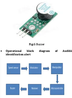
2.5 Buzzer:
A buzzer is a mechanical, electromechanical, magnetic, electromagnetic, electro-acoustic or piezoelectric audio signaling device. A piezo electricbuzzer can be driven by an oscillating electronic circuit or other audio signal source. A click, beep or ring can indicate that a button has been pressed [7]Piezo Buzzer mainly consists of a multi-vibrator circuit, piezoelectric buzzer films, and the resonance box, shell etc. Multivibrator consists of transistors or integrated circuits. When switched on, after (1.5 ~ 15V DC working voltage), multi-harmonic oscillator
start-up, output 1.5 ~ 2.5 kHz of audio signals, which results in audible sound.
Piezoelectric Buzzer contains zircon ate titan ate films from lead or lead magnesium niobate piezoelectric ceramic materials. On both sides of the ceramic coating on the silver electrode by polarization and aging treatment, and then with the brass plates or stainless steel sheets stick together.
Electromagnetic Buzzer works from the oscillator, the electromagnetic coil, magnet, diaphragm and shell so on. After power on, the audio oscillator signal current through the electromagnetic coil, so that the electromagnetic coil produces a magnetic field. Diaphragm in the electromagnetic coil and magnet interaction, periodically
vibrating voice and thus the audible note.
There are too Electromagnetic Buzzers which works without any oscillator. These work by the frequency produced by the make and break contacts to the coil in relation to the moving diaphragm.[12]
Fig:5 Buzzer
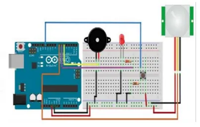
Operational block diagram of Audible identification alert
[image:3.612.52.273.214.540.2] [image:3.612.322.573.354.694.2]© 2018, IRJET | Impact Factor value: 6.171 | ISO 9001:2008 Certified Journal | Page 968 Fig:7 Arduino Base Circuit
3. ADVANTAGES:
1. It will reduce accident due to over speed
2. It will keep driver focus on read while driving
3. As bike will be within specified limit, bike efficiency will increase
4. Cost of this system is less
5. Device is in simple design and light weight
6. It is compact in nature
7. Consumes less amount of power
4. CONCLUSION
In With this concept when vehicle is running at higher speed on road, as speed increases beyond specified limit it will detect by over speed sensor and buzzer will actuate It also minimizes the difficulties of traffic police department and make ease to control the rash driving on highways. The police can perform their duties while sitting in control room and can provide their service with more ease and accuracy. In future Traffic police department can integrate with Audible identification alert to know details (figures) of rash driving vehicles and its locations.
5. Acknowledgment
We would like to express special thanks of gratitude to our teacher (Prof. Harshal D Patil) who gave us his guidance to do this research paper (Study of Audible Identification Alert System For Rash Driving) who also helped us in doing a lot of Research and we came to know about so many new things we are really thankful to them.
6. REFERENCES
[1]www.RoadaccidentstatisticsinindiaNDTVSpecial
project.com Retrieved on 9 march 2018
[2]Pan American Health Organization
(PAHO). http://www.paho.org/English/DD/PIN/whd04_ main.htm, (July 24, 2004). (2004).
[3] Monika Jain1, Praveen Kumar2, Priya Singh3, Chhavi Narayan Arora4, Ankita. Detection of Over Speeding Vehicles on Highways International Journal of Computer Science and Mobile Computing. Vol. 4, Issue. 4, April 2015 ISSN 2320–088X retrieved on 5 march 2018
[4]www.wikipidea.com Retrieved on 7 march 2018
[5] Automation, LJ Welding. "Welding Manipulators |
Subarc Welding & CMT
Manipulators". www.ljwelding.com. Retrieved on 6 march 2018
[6] www.circuittoday.com retrieved on 7 march 2018
[7] www.futureelectronics.com retrieved 7 march 2018.
[8] www.atlas-mag.net.com retrieved 9 march 2018
[9]www.mycardictionary.com Retrieved 13 march 2018 at 3.30pm.
[10]
http://www.techulator.com/resources/4468-Working-Operation-Principle-Modulator.aspx. Retrieved 13 march 2018 at 3.37pm.
[11]
https://www.azorobotics.com/Article.aspx?ArticleID=138. . Retrieved 13 march 2018 at 3.57pm.
[12]
http://www.edaboard.com/showthread.php?t=180369. . Retrieved 13 march 2018 at 4.17pm.
7. AUTHOR PROFILE
Tushar N Kale received Diploma In Mechanical Engineering in 2016 From VYWS Polytechnic Badnera. Published 1 research paper on ‘Design and Analysis of Hover Bike Model’. He now Pursuing Bachelors of Mechanical Engineering Third year at Prof. Ram meghe Institute Of Technology And Research Badnera.
[image:4.612.63.265.81.209.2]© 2018, IRJET | Impact Factor value: 6.171 | ISO 9001:2008 Certified Journal | Page 969 Kailas D Gaware received Diploma In
Automobile Engineering in 2016 From
Government Polytechnic Washim.
Published 1 research paper on ‘Design and Analysis of Hover Bike Model’. He now Pursuing Bachelors of Mechanical Engineering Third year at Prof. Ram meghe Institute Of Technology And Research Badnera.
Prof. Harshal D Patil assistant professor Department of mechanical engineering Prof.Ram Meghe Institute of Technology And Research, Badnera. Received M.E Degree in CAD/CAM and pursuing PhD (Solar Energy). Published 10 research papers.