NONRESIDENT
TRAINING
COURSE
September 1996
Electronics Technician
Volume 8—Support Systems
NAVEDTRA 14093
DISTRIBUTION STATEMENT A: Approved for public release; distribution is unlimited.
Although the words “he,” “him,” and
PREFACE
By enrolling in this self-study course, you have demonstrated a desire to improve yourself and the Navy.
Remember, however, this self-study course is only one part of the total Navy training program. Practical
experience, schools, selected reading, and your desire to succeed are also necessary to successfully round
out a fully meaningful training program.
COURSE OVERVIEW: In completing this nonresident training course, you should be able to: describe
the different liquid cooling systems, dry air systems, ac power distribution systems, ship’s input systems in
terms of their different types, component parts, configuration, operation, and maintenance.
THE COURSE: This self-study course is organized into subject matter areas, each containing learning
objectives to help you determine what you should learn along with text and illustrations to help you
understand the information. The subject matter reflects day-to-day requirements and experiences of
personnel in the rating or skill area. It also reflects guidance provided by Enlisted Community Managers
(ECMs) and other senior personnel, technical references, instructions, etc., and either the occupational or
naval standards, which are listed in the
Manual of Navy Enlisted Manpower Personnel Classifications
and Occupational Standards
, NAVPERS 18068.
THE QUESTIONS: The questions that appear in this course are designed to help you understand the
material in the text.
VALUE:
In completing this course, you will improve your military and professional knowledge.
Importantly, it can also help you study for the Navy-wide advancement in rate examination. If you are
studying and discover a reference in the text to another publication for further information, look it up.
1996 Edition Prepared by
ETC Richard E.Hippey Jr.
Published by
NAVAL EDUCATION AND TRAINING
PROFESSIONAL DEVELOPMENT
AND TECHNOLOGY CENTER
Sailor’s Creed
“
I am a United States Sailor.
I will support and defend the
Constitution of the United States of
America and I will obey the orders
of those appointed over me.
I represent the fighting spirit of the
Navy and those who have gone
before me to defend freedom and
democracy around the world.
I proudly serve my country’s Navy
combat team with honor, courage
and commitment.
C O N T E N T S
Chapter Page
1.
2.
3.
4.
5.
Liquid Cooling . . . 1-1
Dry Air Systems . . . 2-1
AC Power Distribution Systems . . . .3-1
Ship’s Input Systems . . . 4-1
Information Transfer Systems . . . ...5-1
Appendix
I. Glossary . . . AI-1
II. References . . . .. AII-1
SUMMARY OF THE
ELECTRONICS TECHNICIAN
TRAINING SERIES
This series of training manuals was developed to replace the Electronics
Technician 3 & 2 TRAMAN. The content is directed to personnel working
toward advancement to Electronics Technician Second Class.
The nine volumes in the series are based on major topic areas with which the ET2 should be familiar. Volume 1, Safety, provides an introduction to general safety as it relates to the ET rating. It also provides both general and specific information on electronic tag-out procedures, man-aloft procedures, hazardous materials (i.e., solvents, batteries, and vacuum tubes), and radiation hazards. Volume 2, Administration, discusses COSAL updates, 3-M documentation, supply paperwork, and other associated administrative topics. Volume 3, Communication Systems, provides a basic introduction to shipboard and shore-based communication systems. Systems covered include man-pat radios (i.e., PRC-104, PSC-3) in the hf, vhf, uhf, SATCOM, and shf ranges. Also provided is an introduction to the Communications Link Interoperability System (CLIPS). Volume 4, Radar Systems, is a basic introduction to air search, surface search, ground controlled approach, and carrier controlled approach radar systems. Volume 5, Navigation Systems, is a basic introduction to navigation systems, such as OMEGA, SATNAV, TACAN, and man-pat systems. Volume 6, Digital Data Systems, is a basic introduction to digital data systems and includes discussions about SNAP II, laptop computers, and desktop computers. Volume 7, Antennas and Wave
Propagation, is an introduction to wave propagation, as it pertains to
INSTRUCTIONS FOR TAKING THE COURSE
ASSIGNMENTS
The text pages that you are to study are listed at
the beginning of each assignment. Study these
pages carefully before attempting to answer the
questions. Pay close attention to tables and
illustrations and read the learning objectives.
The learning objectives state what you should be
able to do after studying the material. Answering
the questions correctly helps you accomplish the
objectives.
SELECTING YOUR ANSWERS
Read each question carefully, then select the
BEST answer. You may refer freely to the text.
The answers must be the result of your own
work and decisions. You are prohibited from
referring to or copying the answers of others and
from giving answers to anyone else taking the
course.
SUBMITTING YOUR ASSIGNMENTS
To have your assignments graded, you must be
enrolled in the course with the Nonresident
Training Course Administration Branch at the
Naval Education and Training Professional
Development
and
Technology
Center
(NETPDTC). Following enrollment, there are
two ways of having your assignments graded:
(1) use the Internet to submit your assignments
as you complete them, or (2) send all the
assignments at one time by mail to NETPDTC.
Grading on the Internet:
Advantages to
Internet grading are:
•
you may submit your answers as soon as
you complete an assignment, and
•
you get your results faster; usually by the
next working day (approximately 24 hours).
In addition to receiving grade results for each
assignment, you will receive course completion
confirmation once you have completed all the
assignments.
To
submit
your
assignment
answers via the Internet, go to:
http://courses.cnet.navy.mil
Grading by Mail: When you submit answer
sheets by mail, send all of your assignments at
one time. Do NOT submit individual answer
sheets for grading. Mail all of your assignments
in an envelope, which you either provide
yourself or obtain from your nearest Educational
Services Officer (ESO). Submit answer sheets
to:
COMMANDING OFFICER
NETPDTC N331
6490 SAUFLEY FIELD ROAD
PENSACOLA FL 32559-5000
Answer
Sheets:
All
courses
include
one
“scannable” answer sheet for each assignment.
These answer sheets are preprinted with your
SSN, name, assignment number, and course
number. Explanations for completing the answer
sheets are on the answer sheet.
Do not use answer sheet reproductions: Use
only
the
original
answer
sheets
that
we
provide—reproductions will not work with our
scanning equipment and cannot be processed.
Follow the
instructions
for
marking your
answers on the answer sheet. Be sure that blocks
1, 2, and 3 are filled in correctly. This
information is necessary for your course to be
properly processed and for you to receive credit
for your work.
COMPLETION TIME
PASS/FAIL ASSIGNMENT PROCEDURES
If your overall course score is 3.2 or higher, you
will pass the course and will not be required to
resubmit assignments. Once your assignments
have been graded you will receive course
completion confirmation.
If you receive less than a 3.2 on any assignment
and your overall course score is below 3.2, you
will be given the opportunity to resubmit failed
assignments.
You
may
resubmit
failed
assignments only once. Internet students will
receive notification when they have failed an
assignment--they may then resubmit failed
assignments on the web site. Internet students
may
view
and
results
for
failed
assignments from the web site. Students who
submit by mail will receive a failing result letter
and a new answer sheet for resubmission of each
failed assignment.
COMPLETION CONFIRMATION
After successfully completing this course, you
will receive a letter of completion.
ERRATA
Errata are used to correct minor errors or delete
obsolete information in a course.
Errata may
also be used to provide instructions to the
student.
If a course has an errata, it will be
included as the first page(s) after the front cover.
Errata for all courses can be accessed and
viewed/downloaded at:
http://www.advancement.cnet.navy.mil
STUDENT FEEDBACK QUESTIONS
We value your suggestions, questions, and
criticisms on our courses. If you would like to
communicate with us regarding this course, we
encourage you, if possible, to use e-mail. If you
write or fax, please use a copy of the Student
Comment form that follows this page.
For subject matter questions:
E-mail:
[email protected]
Phone:
Comm: (850) 452-1001, Ext. 1713
DSN: 922-1001, Ext. 1713
FAX: (850) 452-1370
(Do not fax answer sheets.)
Address:
COMMANDING OFFICER
NETPDTC N315
6490 SAUFLEY FIELD ROAD
PENSACOLA FL 32509-5237
For
enrollment,
shipping,
grading,
or
completion letter questions
E-mail:
[email protected]
Phone:
Toll Free: 877-264-8583
Comm: (850) 452-1511/1181/1859
DSN: 922-1511/1181/1859
FAX: (850) 452-1370
(Do not fax answer sheets.)
Address:
COMMANDING OFFICER
NETPDTC N331
6490 SAUFLEY FIELD ROAD
PENSACOLA FL 32559-5000
NAVAL RESERVE RETIREMENT CREDIT
Student Comments
Course Title:
Electronics Technician, Volume 8—Support Systems
NAVEDTRA:
14093
Date:
We need some information about you:
Rate/Rank and Name: SSN: Command/Unit
Street Address: City: State/FPO: Zip
Your comments, suggestions, etc.:
Privacy Act Statement: Under authority of Title 5, USC 301, information regarding your military status is requested in processing your comments and in preparing a reply. This information will not be divulged without written authorization to anyone other than those within DOD for official use in determining performance.
CHAPTER 1
LIQUID COOLING SYSTEMS
Liquid cooling systems are vital to the proper operation of shipboard electronic equipment. Because of their importance, these cooling systems must be reliable and readily available. Study the contents of this chapter carefully. The knowledge you acquire may one day help you prevent heat damage to a multimillion dollar piece of equipment and the loss of countless manhours being expended in its repair. Imagine how you would feel if the damage occurred because you had not checked a temperature gauge at a particular time because you were not aware of its purpose or existence. Knowledge of the equipment is one of the greatest safeguards that you can develop. Let us begin by discussing the methods for cooling electronic equipments and systems.
ELECTRONIC EQUIPMENT COOLING METHODS
Most electronic equipment generates sufficient heat so that some form of equipment cooling is required during normal operation. Heat is generated by various parts of the equipment because electrical energy is dissipated in the form of heat whenever current flows through a resistance. This heat must be removed to prevent a change in the equipment’s operating parameters and to prevent possible breakdown of electronic parts.
This section on liquid cooling systems describes some of the more common methods of heat removal from electronic equipment. It provides the basic knowledge necessary for better understanding of the major components, operation, and maintenance of a typical cooling system. Our discussion will highlight four methods of cooling: convection, forced-air, air-to-air, and air-to-liquid.
CONVECTION COOLING
Cooling by the convection principle is shown in figure 1-1. As the heat of an equipment part warms the air in its vicinity, the warm air, being lighter, rises through the outlet openings. The cooler air is drawn in through the inlet openings to replace the warm air. This method is limited in its cooling effect because it relies
Figure 1-1.-Convection cooling.
upon the natural airflow and requires that the equipment enclosure be of open construction without air falters.
To increase heat dissipation, a finned heat sink can be added to the heat-producing part, as shown in figure 1-2. The fins increase the effective surface area of the part, allowing more heat to be transferred to the air. For the maximum transfer of heat, the part must make contact with the heat sink. Silicone grease is usually applied between the heat source and heat sink for better thermotransfer. The heat sink must be kept free of any dirt or dust, which would act as an insulator.
Figure 1-3.—Forced-air coding.
FORCED-AIR COOLING
The increase the cooling effect over that provided by convection cooling, forced-air cooling (fig. 1-3) uses a blower to provide air movement instead of the natural convection currents. Cool air is drawn into the equipment enclosure and flows past the heat producing part, picking up the heat. The air is then exhausted out of the equipment. An air filter is provided at the air inlet to remove dust and dirt that otherwise would settle on the internal parts of the equipment. The air filter must be kept clean according to the equipment’s maintenance requirements. This will ensure maximum air movement and cooling.
In some equipment, a honeycomb rf interference filter is installed on both input and outlet to prevent stray rf from entering or leaving the equipment cabinet. This filter can also collect dirt that can reduce the airflow.
Failure of a bearing in the blower motor is not an uncommon problem. A replacement of both blower
motor bearings or blower assembly is warranted at the first sign of abnormal operation, such as excessive noise or vibration. It is better to replace the bearings than to risk damage to the equipment that the blower motor is designed to protect.
AIR-TO-AIR COOLING
Some units of electronic equipment are hermetically sealed to prevent the entrance of moisture. For equipment of this type, an air-to-air heat exchanger (fig. 14) is used to prevent the air inside the equipment enclosure from mixing with the outside air and still allow cooling to take place. Air moving past the heat producing part absorbs heat and is forced through a heat exchanger by an internal blower. The heat in the internal air is absorbed by the heat exchanger. The cooled internal air is then returned to the equipment interior to continue the cycle.
Heat is removed from the heat exchanger by forcing cool outside air through the heat exchanger by an external blower. There is no physical contact between the internal and external air. In some applications, the internal air is replaced by an inert gas such as nitrogen to prevent oxidation.
AIR-TO-LIQUID COOLING
A more efficient heat transfer is possible by replacing the air-to-air heat exchanger with an air-to-liquid heat exchanger (fig. 1-5). In this method, the internal air is also circulated past the heat producing part and through a heat exchanger, but the heat is removed from the heat exchanger by a liquid coolant circulating through the heat exchanger.
Air-to-liquid cooling systems usually employ built-in safety devices to shut down the equipment to prevent overheating.The overheating could be caused by low or no liquid flow, liquid too hot, an inoperative circulating fan, or reduced heat exchanger efficiency because of improper maintenance.
This type of cooling system is normally found on large equipment instillations where a huge amount of heat is developed. Many radar transmitters, for example, require cooling of this type. The other types that we have discussed would not be able to dissipate the heat that a high-powered radar transmitter develops. A disadvantage of this type of cooling system is that they are larger and more complex. However, for this reason and because they are a part of the more complex systems, we describe the typical liquid cooling system used aboard ship. In this way, you will be given abetter understanding of the function of individual components within a system and the basic maintemnce required to maintain the system to a high state of readiness.
LIQUID COOLING
Cooling systems are essential to the satisfactory operation of all shipboard combat systems equipment. In fact, some form of cooling is required for all shipboard electronic equipment. As we have indicated, liquid cooling is especially efficient for the transfer of large amounts of heat. To maintain cooling systems, you must have a broad understanding of the different types of liquid cooling systems with which you are involved.
A typical liquid cooling system is composed of two basic coolant systems. First, there is the primary system. It provides the initial source of cooling water that can be either seawater (SW) or chilled water (CW) from the ship’s air-conditioning plant, or a combination of both. Next, the secondary system transfers the heat load from the electronic equipment to the primary system. The coolant normally used in the secondary system is distilled water (DW). This distilled water is
ultrapure and is maintained in that state by a
demineralize. In some secondary systems, ethylene glycol is added to the water to prevent freezing when the system is exposed to freezing weather.
TYPES OF LIQUID COOLING SYSTEMS
In the U.S. Navy, there are three basic configurations of liquid cooling systems, and conceivably you could be involved with all three. The type or types with which you maybe involved, depends upon the number and types of electronic equipment to be cooled. The three types of systems areas follows:
Type I—Seawater/distilled water (SW/DW) heat exchanger with SW/DW heat exchanger standby
Type II—SW/DW heat exchanger with a chilled requirements of the equipment. Some electronic water/distilled water (CW/DW) heat exchanger equipments require very close regulation of the
standby temperature of the distilled water; whereas, others do
Type III—CW/DW heat exchanger with a not. CW/DW heat exchanger standby
-Type I (SW/DW) systems are used for electronic The specifications for the type of system installed system installations that can be operated satisfactorily on your equipment will depend upon the operational with seawater temperature as high as 95°F. This should
result in a distilled water supply temperature to the electronics of approximately 104°F. Type II (SW/DW, CW/DW) systems are used in installations that cannot accept a DW temperature higher than 90°F. Type III (CW/DW) systems are used in installations where the temperature range is critical. They require close regulation of the DW coolant to maintain temperatures between established limits. For example, the
temperature limits might be 70°F and 76°F. As you can see, Type III systems are used where tighter control is required.
Liquid cooling systems are composed of piping, valves, regulators, heat exchangers, strainers, circulating pumps, expansion tanks, gauges, and a demineralize. In some systems, there are specialized components to monitor cooling water to the electronic equipment. Let’s examine this in greater detail by discussing the operation of the three types of liquid cooling systems. Before doing so, however, let’s look at the systems in terms of primary and secondary systems.
PRIMARY COOLING SYSTEM
The cooling water for the primary cooling system is either seawater or chilled water. The seawater, obviously, is from the sea and the chilled water is from the ship’s air-conditioning plant. Figures 1-6,1-7, and 1-8 show the basic arrangements of systems using seawater and chilled water.
In figure 1-6, seawater from a sea connection is pumped by a seawater circulating pump in one of the ship’s engineering spaces through a duplex strainer to remove all debris and then through the tubes of a heat exchanger. Finally, it is discharged back into the sea at an overboard discharge. The seawater system shown in figure 1-6 is a multiple-branch system. As such, it supplies a number of heat exchangers for electronic equipment. To regulate the proper amount of seawater to each cooling system, an orifice plate is installed in the line between each heat exchanger and the duplex strainer. The heat exchangers are referred to as seawater-to-distilled-water heat exchangers.
Another means of providing seawater is through the ship’s firemain, as shown in figure 1-7. The seawater is
Figure 1-8.—Type III liquid cooling system.
taken from the firemain through a duplex strainer and a flow regulator (orifice plate) to and through the heat exchanger. It is then discharged overboard. The connection to the firemain is permanent.
The ship’s fire pump, not shown in figure 1-7, is used to pump seawater into the firemain. The fire pump is similar in design to the previously mentioned seawater circulating pump, except it has a much larger capacity.
Another means of getting seawater as a primary coolant is by an emergency connection (figs. 1-6 and 1-7). This method is used if the normal seawater supply is lost. The connection is usually by means of a 1-inch fire hose. The emergency supply comes from an alternate portion of the ship’s firemain or a portable pump rigged by the ship’s damage control party. The portable emergency hose is normally stored in the liquid coolant machinery room.
Note: Seawater systems are referred to as open-looped or one-pass because the seawater flows through the system only once.
In figures 1-7 and 1-8, chilled water is taken from the supply main of the air-conditioning, chilled-water
systems. The chilled water is used as a backup source of cooling water for the primary cooling system shown in figure 1-7, and as a normal and backup source in the system shown in figure 1-8. The chilled water flows through the tubes of the heat exchanger (chilled water to distilled water), a flow regulator, and back to the chilled-water system. A temperature regulating valve at the inlet of the heat exchanger regulates the flow of chilled water through the heat exchanger to maintain the required water temperature in the secondary system (distilled water). The ship’s air-conditioning, chilled-water circulating pump is used to pump the chilled water through the heat exchanger. The chilled- water system is a closed-loop water system because the water is recirculated. It must be kept tight and free from leaks to assure satisfactory operation.
SECONDARY COOLING SYSTEM
electronic equipment being cooled, a demineralize, a temperature control valve, monitoring equipment with its associated alarms, and the heat exchanger, which is shared with the primary system. The secondary system is a closed-loop water system, as compared to the seawater system, which is a one-pass or open-loop system.
TYPE I COOLING SYSTEM
We are now ready for a more detailed look at the types of cooling systems. Let’s begin by looking at the Type I system. Starting with the distilled water pumps (fig. 1-6), distilled water under pressure flows to the temperature regulating valve. The temperature regulating valve is installed to partially bypass distilled water around the seawater- to-distilled-water heat exchanger so that a constant water temperature can be supplied to the electronic equipment. As the temperature in the distilled water increases, more water is directed to the heat exchanger and less to the bypass line. ‘his maintains the output water temperature constant. The standby heat exchanger is usually of the same design and is used when the online heat exchanger is inoperable or experiencing maintenance.
The size of the heat exchanger is designed to handle the full cooling load of the electronic equipment plus a 20 percent margin. From the heat exchanger, the water then goes through various monitoring devices, which check the water temperature and flow. These two things depend upon the requirements of the electronic equipment being coded. After the water moves through the equipment, it is drawn back to the pump on the suction side. In this way, a continuous flow of coolant is maintained in a closed-loop system.
An expansion tank is provided in the distilled water system to compensate for changes in the coolant volume, and to provide a source of makeup water in the event of a secondary system leak. When the expansion tank is located above the highest point in the secondary system and vented to the atmosphere, it is called a gravity tank. If it is below the highest point in the secondary cooling system, then it is called a compression tank, because it requires an air charge on the tank for proper operation.
‘The demineralize is designed to remove dissolved metals, carbon dioxide, and oxygen. In addition, a submicron falter (submicron meaning less than one millionth of a meter) is installed at the output of the demineralizer to prevent the carry-over of chemicals into the system and to remove existing solids.
TYPE II COOLING SYSTEM
‘he secondary system of the Type II cooling system (fig. 1-7) is similar to the Type I secondary coolant system and uses many of the same components. The major difference is in the operation of the CW/DW heat exchanger. The secondary coolant is in series with the SW/DW heat exchanger and automatically supplements the cooling operation when the SW/DW heat exchanger is unable to lower the temperature of the distilled water to the normal operating temperature. The CW/DW temperature regulating valve allows more chilled water to flow in the primary cooling system to the CW/DW heat exchanger. This causes the temperature in the secondary system to go down. Normally, this action only occurs in the event of high seawater temperatures encountered in tropic waters. The CW/DW heat exchanger is also used in the event of an SW/DW heat exchanger malfunction.
TYPE III COOLING SYSTEM
The Type III secondary cooling system (fig. 1-8) also operates in a similar manner to the Type I system. The major difference is in the way that the temperature of the secondary coolant is regulated. A three-way temperature regulating valve is not used. A two-way temperature regulating valve is used in the primary cooling loop to regulate the temperature of the secondary loop.
The duplicate CW/DW heat exchanger is installed parallel to the first heat exchanger and is used as a standby heat exchanger. In the event that a malfunction occurs requiring the first heat exchanger to be removed from service, the standby exchanger can be put into service by manipulating the isolation valves associated with the two heat exchangers.
COOLING SYSTEM COMPONENTS
You should be able to identify and describe the operation of the individual components of a typical cooling system. This will help you to perform the required system maintenance and trouble isolation. You should never neglect the cooling system, because it will quickly deteriorate to a point where only extreme and costly maintenance will restore the system to its proper performance.
HEAT EXCHANGERS
Figure 1-9.-Single-pass SW/DW heat exchanger with double-tube sheets.
electronic components is transferred to the primary cooling system, which contains either seawater or chilled water from an air-conditioning plant. In both cases (figs. 1-9 and 1-10), the heat exchangers are of the shell- and tube-type in which the secondary coolant (distilled water) flows through the shell, while the primary coolant (seawater or chilled water) flows through the tubes.
A single-pass counterflow heat exchanger (fig. 1-9) is more efficient than the double-pass heat exchanger, because there is a more uniform gradient of temperature difference between the two fluids. In figure 1-9, the primary coolant (SW/CW) flows through the tubes in the opposite direction to the flow of the secondary coolant (DW). Heat transfer occurs when the seawater flows through the tubes; extracting heat from the distilled water flowing through the shell side of the heat exchanger. The distilled water is directed by baffles to flow back and forth across the tubes as it progresses
along the inside of the shell from inlet to outlet. In figure 1-9, the preferred method of double-tube sheet construction is shown. Single-tube sheet construction is shown in figure 1-10.
Double-tube sheets are used at both ends of a tube bundle. A void space between the sheets prevents contamination of the distilled water and permits the monitoring of water loss because of tube leakage. You should be on the lookout to detect leakage at the “telltale drains,” which indicates a failure of a tube joint. The type of water leaking out indicates whether the failure is in the primary or the secondary system. The telltale drains should never be plugged or capped off. A leak in one of the tubes shows up as a loss of water in the secondary side of the liquid coolant system, because it operates at a higher pressure than the primary side. his is intentional. This ensures that the distilled water is not contaminated with seawater when a leak develops in a heat exchanger.
A double-pass heat exchanger is generally used ensure that tools, such as screwdrivers and wire brushes, when there is limitation on the installation of the heat are not used in such a way that they may scratch or mar exchanger. This type of heat exchanger is less efficient the tube surfaces.
than a single-pass exchanger and is subject to internal
undetectable leakage across the flow divider in the Over a period of time, electrolysis, which results inlet-outlet water box. because of dissimilar metals in the cooling system, will slowly dissolve the insides of various components in the It is to your advantage to maintain a log on the
performance of the heat exchangers installed in the cooling systems with which you are involved. By recording the operating characteristics, you will have the data you will need to later analyze the performance of the heat exchanger. The performance is monitored by observing the temperature gradient (AT) between the inlets and outlets of the two fluids. The overall effectiveness of a heat exchanger is determined by comparing its primary inlet temperature to its secondary outlet temperature. For example, with no change in the primary or secondary flow and if the heat transfer capacity of the heat exchanger drops, the AT will increase. By comparing the AT readings taken periodically with the clean heat exchanger AT readings, you can detect the deterioration of a heat exchanger because of fouling. By maintaining a record of both input and output pressure gradient you will be able to determine which side of the heat exchanger is fouled.
Heat exchangers must periodically be cleaned. The secondary section (distilled water) is cleaned by circulating chemicals through the secondary cooling system to remove any buildup of scale deposits, which accumulate on the surface of the tubes. The procedure for routine cleaning of the primary section of the heat exchanger is to first secure the sea connections to prevent flooding. In some cases, an inspection port in the water box can be opened to remove any foreign matter lodged inside and against the tubes. If you are unable to get at the ends of the heat exchanger to remove the water boxes, then you must remove the heat exchanger from its location and place it on the deck or a suitable work surface. Mark each unit removed so that it can be positioned in its proper place during reassembly. With the water boxes removed, an air lance should be passed through each tube and the passages washed out. Where severe fouling exists, a water lance should be pushed through each tube to remove foreign matter attached to the tube walls. Where extreme fouling exists, special cleaning equipment operated by personnel skilled in their use is required. The ship’s engineering officer is the best person qualified to determine which procedure to use and whether the job can be performed aboard ship or if it must be transferred to a repair facility. You should take precautions to
primary seawater cooling system. (Electrolysis is not a problem in chilled water systems to the extent that it is in seawater systems.) The type of metal used in the fabrication of the heat exchanger tubes is the deciding factor as to the use of zincs anodes or zincs. Zincs are disks, rods, bars, or plates made of zinc metal that are installed inside the heat exchanger’s water boxes. When zincs are installed, the electrolytic action is concentrated on the zinc and not on the metal of the heat exchanger tubes. As electrolysis dissolves the zincs instead of the heat exchanger tubes, they should be replaced. (The purity of distilled water inhibits electrolysis in the secondary system.) In an older cooling system, you should be on the lookout for thin pipes in the seawater side of the cooling system. You can check forbad pipes by gently tapping the empty pipes with the ball of a ball-peen hammer. A bad piece of pipe will make a dull sound and dimple as it is struck lightly. This work should be scheduled for overhaul while the ship is inport.
EXPANSION TANK
The expansion tank serves a threefold purpose in a liquid cooling system. First, it maintains a positive pressure required on the circulating pump inlet for proper operation of the circulating pump. Second, the expansion tank compensates for changes in the coolant volume because of temperature changes. Third, it vents air from the system and provides a source of makeup coolant to compensate for minor losses because of leakage or losses that occur during the replacement of radar equipment served by the system. The tank maybe either a gravity tank or a pressurized tank.
When an expansion tank is used as a gravity tank (fig. 1-11), it is located above the highest point in the distilled water system.
This provides sufficient pressure to the suction side of the circulating pump. This also ensures a flow of water from the tank into the system when makeup water is required. The tank is provided with a sight glass to check the level of water in the tank. The sight glass should normally show the tank to be two-thirds to
Figure 1-11.-Gravity expansion tank.
four-fifths full. The glass should be redlined at four-fifths of the tank capacity. A vent pipe is located on the top of the tank to prevent air pressure from building up in the system. A valve and funnel connection with cap is located on the top of the tank to provide a means for filling the system with distilled water. A low-level alarm switch is usually set at 20 percent of tank capacity. When the fluid level in the tank lowers to 20 percent of the full level, visual and audible alarms actuate at the alarm switchboard to warn personnel when the system is low on distilled water. If the tank should run out of water, then air is drawn into the system, which results in increased corrective maintenance on the system to remove the trapped air or possible pump damage and/or failure of high power transmitter components.
The pressurized expansion tank (fig. 1-12) is normally located near the circulating pump suction in the return main of the secondary liquid cooling system. The pressurized tank is airtight and is charged with compressed air to an appropriate pressure from the ship’s low-pressure air system. In some systems, a hose
is used to pressurize the tank through a quick disconnect or Schrader valve.
In other systems, a permanent pipe installation is connected to the expansion tank through a pressure-relief valve and an air shutoff valve. The ship’s low-pressure air system is used to charge the pressure tank, and then it is secured to prevent a possible floodback of coolant into the low-pressure air system. The relief valve is provided to protect the tank and distilled water system from being overpressurized. The sight glass and the low-level alarm switch function the same as those on the gravity expansion tank.
In both types of expansion tanks, the bottom of the tank is connected by piping to the return main of the secondary cooling system (fig. 1-6). Changes in coolant volume causes the coolant to flow into or out of the reservoir as necessary to maintain a stable, liquid coolant, return-line pressure.
Makeup water (distilled water) is added to the expansion tank through the funnel located on the top of the tank (fig. 1-11 and 1-12). A funnel cap is provided for the funnel to prevent dirt from entering the system through the funnel. Whenever you fill the pressurized expansion tank, you have to first isolate the tank from the cooling system and the air supply, then vent the air pressure off through the vent pipe located at the top of the tank. The makeup water can be obtained directly from the ship’s evaporators and preferably when the ship is making boiler feed water, because the water is double distilled. At NO time should potable (drinking) water or treated boiler feed water be used in any electronic cooling systems. After the water is drawn from the ship’s evaporators, it should be transported using only a clean capped container. You should take a sample of the water from the containers and have it
tested for chloride by the ship’s water test facility before any of the water is used in the cooling system. The maximum permissible level of chloride is .065 epm (equivalent parts per million). The supply system provides an alternate source of makeup water.
The expansion-tank sight glass is your best indication of a coolant leak in the secondary cooling system. When the system uses excessive makeup water, you should inspect the whole secondary system, including the telltale drains on the heat exchanger, to locate the source of the leak. A small drip can amount to several gallons of water a day. On the pressurized expansion tank, a very small air leak indicated by a pressure drop on a tank gauge can be located by brushing on a leak detector (a thick, clear, soapy liquid such as concentrated liquid dishwasher soap) over the suspected area of the leak. The escaping air causes bubbles to form in the leak detector.
SEAWATER STRAINERS
Strainers are used in the seawater cooling system to remove debris and sea life, which could clog the pressure and flow control device (orifice) and/or the tubes of the heat exchanger. The two types of in-line seawater strainers most commonly used in weapons cooling systems are the simplex (single) and duplex (double) basket strainers.
The simplex basket strainer (fig. 1-13) consists of a Y-pattern body housing a wire mesh basket. Some simplex strainers have a small drain on the cover to allow you to drain the water off before removing the cover. The basket is removed periodically for cleaning and inspecting for deterioration. This type of strainer requires that the seawater be secured before you clean the basket.
The duplex strainer (fig. 1-14) consists of two removable baskets located in parallel at the seawater inlet. Seawater flows into the top of one basket and out through the perforated sides to the outlet. This arrangement allows maintenance to be performed on one basket while the system is in operation, A selector valve is arranged so that with the handle in one position, seawater flows through one of the baskets, leaving the other basket accessible for removal and cleaning. By switching the valve handle to the alternate position, flow is shifted over to the other basket.
A duplex pressure gauge monitors the differential pressure between the inlet and outlet ports of the duplex strainer. The purpose of the duplex gauge is to provide a visual indication of a clogged strainer basket. To correctly use the gauge, it should be marked when the basket is clean. When the basket is clogged, the pressure reading is usually 5 to 10 psi above the clean-basket reading. If the pressure drop is less than the clean-basket reading, a check should be made for a damaged basket or missing basket.
The basket handle (spring handle) acts as a spring-load to seat and hold the basket in the housing. A damaged spring handle will permit debris to bypass the strainer basket and clog the heat exchanger tubes. In some cases, the basket may spin inside the duplex strainer and physically wear away the basket seat and/or the side of the duplex strainer. The duplex strainer would then have to be removed for extensive repairs, possibly off ship. New or replacement baskets should
always be checked for proper spring-handle pressure against the top of the basket cover. You should use only the correct gasket material for the basket covers, as specified in the COSAL. Inferior material can stretch and be forced out from under the cover, and then seawater could spray out and possibly flood the space.
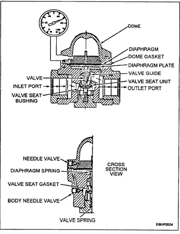
TEMPERATURE REGULATING VALVES
The temperature regulating valve regulates the amount of cooling water flowing through or bypassing a heat exchanger to maintain a desired temperature of distilled water going to the electronic equipment. Temperature regulating is usually provided by either a three-way or a two-way temperature regulating valve or a combination of both valves, as shown in figure 1-7. The three-way valve is used where seawater is the primary cooling medium in the heat exchanger, and the two-way valve is used where chilled water is the primary cooling medium.
Three-Way Temperature Regulating Valve
The three-way regulating valve (fig. 1-7) is installed so that the incoming distilled water to the valve can be directed to the heat exchanger or caused to bypass the heat exchanger. More accurately, the distilled water is proportioned between these two paths. The valve senses the temperature of the distilled water downstream of the junction between the heat exchanger
outlet and the bypass and then proportions the two flows to obtain the desired temperature. The three-way regulating valve’s range of operation is within degrees of the setting on the valve.
Refer to figure 1-15 for the following description of the operation of the three-way regulating valve.
The bulb contains a volatile liquid that vaporizes and expands when heated. The generated pressure in the bulb is a function of the temperature around it. This pressure is transmitted through capillary tubing to the flexible bellows, which are loaded by the spring. Both bellows and spring rest on the end of the valve stem. Expansion or contraction of the bellows causes movement of the stem and the piston in the valve body. The flow of the liquid entering the valve at port A is
proportioned between ports B and C in the proper ratio to maintain the mixed flow temperature at the valve’s
set point. Total flow through the valve remains
constant. Movement of the bellows is opposed by the spring, which is provided with a means to adjust the operating temperature by the spring-tension adjustment wheel. A drop in temperature at the thermostatic bulb reduces the pressure in the thermostatic assembly, causing it to exert less force, resulting in an upward movement of the stem because of the force of the spring. As the stem is connected to the piston, the piston also moves upward, enabling more liquid to pass from the bottom inlet through the right outlet (bypass) side and, at the same time, restricting flow through the left outlet (heat exchanger) side. A rise in temperature at the thermostatic bulb results in a reversed effect.
Two-Way Temperature Regulating Valve
The two-way temperature regulating valve (fig. 1-16) is normally installed in the chilled water supply to the heat exchanger with the thermostatic sensing bulb installed in the distilled water outlet from the heat exchanger.
It is shown as installed in the system on diagrams figures 1-7 and 1-8. The basic operation of the two-way temperature regulating valve is the same as the three-way temperature regulating valve. If the temperature of the distilled water is above the desired temperature, the two-way valve gradually opens to increase the flow of chilled water through the heat exchanger, which keeps the distilled-water temperature at the desired point.
Both the three-way and two-way temperature regulating valves have a manual override feature to provide uninterrupted service, if and when the thermostatic assembly fails because of damage to the capillary tubing or any other component of the thermostatic assembly. With the use of the manual override wheel, you can set the valve plunger/piston in the required position to operate the liquid cooling system by turning the manual override wheel down (from right to left) until it touches the spiral pin in the valve stem. Beyond this point, the valve plunger/piston is forced down, allowing the flow of cooling medium through the valve. With the use of the installed thermometers, you can decide if more or less cooling is needed by turning the manual override wheel up or down. The use of the manual override inhibits the thermostatic assembly and should only be used when
the thermostatic assembly is inoperable. Corrective maintenance of the regulating valve consists of inspecting the valve for leaks and for freedom of stem movement, adjusting the set point at which the valve regulates, renewing the thermostatic assembly, and cleaning and restoring valve parts. Any time that you remove a valve, you should center punch a dot code on each piece to ensure that the valve and piping are installed in the original configuration. The three-way valve can be turned around, and the problem could go unnoticed until you try to align the temperature regulation of the cooling system. There are individual manuals for the temperature-regulating valves and they should be closely followed. For example, if you remove the top of the thermostatic assembly without chilling the temperature probe, the bellows will expand and rupture, making the unit worthless. To verify that the thermostatic assembly has failed, close valves upstream and downstream of the thermostatic bulb, drain the unit below the location of the bulb, and remove the bulb from its well. Place the bulb in a suitable vessel and observe the valve stroke while the bulb is alternately heated with hot water and cooled with cold water. If the valve thermostatic assembly does not respond, it has lost its thermostatic charge, and a new unit must be installed.
FLOW REGULATORS
You will encounter many different types and sizes of flow regulating devices used in both the primary and secondary cooling systems. They are used to reduce the pressure or the flow of coolant through a cooling system.
The orifice plate is found primarily in the seawater cooling system. It is the simplest design of a flow regulating device, consisting of a steel plate with a hole in it. With constant known seawater pressure and with a given hole size, the volume of water through the device can be determined. The use of an orifice plate is limited to where the input water pressure is essential y constant, such as the ship’s firemain. The orifice plate is normally installed between two pieces of flanged pipes upstream from the heat exchanger as shown in figures 1-6 and 1-7. This will reduce the ship’s firemain pressure below the pressure in the secondary cooling system. As we have indicated earlier, should one of the heat exchanger tubes fail, the seawater pressure is lower than the distilled water pressure; therefore, it would not contaminate the secondary cooling system. The secondary cooling system would force distilled water into the primary cooling system. A ruptured heat exchanger tube or a bad single tube sheet in a heat exchanger would give no visual indication of water loss except for the indication
on the expansion tank sight glass. To stabilize the flow of seawater and to prevent jet erosion of the heat exchanger and associated piping, the orifice plate should be installed with at least 15 pipe diameters of straight pipe upstream from the heat exchanger. When there is a drop in the heat exchanger primary input pressure and the seawater supply pressure has not changed, you should first check the duplex strainer differential pressure gauge to ensure that the duplex strainer is clean. Then the orifice plate should be inspected for deposits or particles that could restrict the seawater flow. You should also inspect the orifice plate for erosion damage of the hole diameter. The orifice plate should be replaced when there is an increased flow of seawater to the point that it could damage the heat exchanger. Never use the seawater valves to throttle (partially closed) the flow of seawater in the primary cooling system, because the seawater will erode the internal parts of the valve. The damage to the valve would require extensive repair or replacement, because the valve would no longer close properly.
When used with the chilled-water system, the constant flow regulator (variable orifice, fig. 1-17) is installed downstream from the heat exchanger. This restricts the flow from the heat exchanger and keeps the heat exchanger fully submerged for greater efficiency (heat transfer). This type of flow regulator is not used in the seawater system because the internal parts would easily become fouled with marine growth and deposits. The operation is dependent on the movement of the orifice plugs (neoprene) to regulate the flow of water.
Another type of flow-regulator valve (equipment flow) used primarily with electronic equipment to regulate the flow of distilled water through the
Figure 1-18.—Equipment flow regulator.
individual cabinets and components is shown in figure 1-18. It maintains a constant flow of distilled water with limited changes in the input pressure. At the minimum water flow, the total amount of water is passed through the device. As the flow of water increases to the flow regulators maximum limit, the water flow is restricted by the insert’s movement, which causes the hole size to decrease. In this way, the flow of water is regulated. The amount of water that the flow regulator will pass is usually stamped on the side of the regulator. This is because the external dimensions are usually the same for differently rated regulators.
The nominal flow rate of the equipment-flow regulator can be from one-half to more than 12 gallons per minute. It is normally used with a pressure-regulating valve. You should be aware that this type of regulator can deteriorate over time. The insert can become distorted and cause a reduction in the flow of water. With a drill index set, you can use the back of a drill bit to measure the hole size and compare it to a known good constant-flow regulator or the equipment manual. Do not drill out the insert to restore it to the proper size, because it will become distorted. Its distorted shape would prevent the insert from regulating the distilled water flow.
The pressure-regulating valve (fig. 1-19) is used to regulate a major section of the coolings system; whereas, the flow regulator is normally used to regulate an individual feeder line to an individual component or cabinet. The pressure-regulating valve usually has a pressure-relief valve downstream from it to protect the equipment from being over pressurized. Should a failure occur in the pressure regulating valve, the pressure-relief valve would keep the water pressure at a safe level to prevent equipment damage.
The operation of a typical pressure-regulating valve is as follows: When a drop in downstream (outlet) pressure occurs, the pressure in the diaphragm chamber is lowered concurrently. The downstream side of the valve is connected to the diaphragm chamber through a narrow opening along the periphery of the piston. The
Figure 1-20.-Cooling system flow switch.
spring is allowed to force the diaphragm downward releasing the tension on the rocker arm, and the inlet pressure opens the valve. The outlet pressure increases to the preset level, and the static control chamber pressure balances the valve spring to maintain a regulated downstream pressure to the served equipment.
You should take the following precautions with this type of valve. Ensure that the locknut is loose before you adjust the adjusting screw; otherwise, you could strip the threads of the brass spring chamber. If water should start leaking out of the vent, the valve should be serviced for a leaking diaphragm. This should be done before it ruptures. The vent should never be plugged or painted over. Either would inhibit its operation.
If you should remove a flow regulator or a pressure regulator, make certain that you reinstall it correctly, because it can be installed backwards. Look for an arrow for direction of flow or the inlet and outlet stamped on the body of the device. Pipe-joint sealant should be used only on the male pipe threads and not closer than one thread to the open end to seal the device. Improper use of anti-seize tape can result in the tape being cut loose and circulated in the cooling system, which could plug up a small component.
FLOW MONITORING DEVICES
Most systems incorporate one or more types of devices to monitor the flow of distilled water through the system to ensure that the electronic equipment is supplied with an adequate flow. A low-flow switch is normally found in the secondary cooling system to monitor the overall coolant flow. It is electrically connected to a common alarm circuit to warn personnel when the system flow rate drops below a specified minimum value. A typical cooling system low-flow
switch is shown in figure 1-20. The main operating parts consist of a hermetically-sealed reed switch and a permanent magnet attached to an internal shuttle. With the proper flow of coolant, the shuttle moves the magnet up and away from the reed switch. This keeps the reed switch contacts open, When the coolant flow drops below the minimum for a flow switch, the shuttle is forced down by the spring to a balanced condition against the flow of the distilled water. The magnetic field is now close enough to cause the reed switch to close and activate the low-flow alarm.
A much smaller flow switch is used in electronic equipment to monitor the flow to individual components. Atypical equipment flow switch is shown in figure 1-21. The one depicted contains a fixed orifice.
The flow of water through the orifice causes a pressure drop across it. This pressure drop causes the diaphragm to move against the spring. When the
Figure 1-22.-Venturi flowmeter.
differential pressure (pressure drop) is sufficient, the microswitch will activate to indicate that the switch has the proper flow through it. You should be sure that the flow switch is defective before overhauling or replacing it. The problem could be a partially closed supply/return valve, obstruction in the coolant line, insufficient coolant pressure, or many other things. By using the coolant system pressure gauges and/or the installation of a permanent or a temporary in-line flowmeter, you should be able to correctly isolate the problem.
In the secondary cooling system, a full-flow system flowmeter (figs. 1-6, 1-7, and 1-8) is provided to enable you to monitor the total system flow rate for troubleshooting purposes. There are three types of system flowmeters installed aboard ship. All of them serve the same functional purpose of monitoring coolant flow rate. You will encounter the venturi-type flowmeter, orifice-type flowmeter, and the rotameter flowmeter. Most systems incorporate one secondary coolant flowmeter and one or more smaller flowmeters to ensure that the electronic equipment is being supplied with an adequate flow of coolant.
In the venturi-type flowmeter (fig. 1-22), as the coolant approaches the contracted portion (throat) of the meter, its velocity must increase as it flows through the contracted zone. The angle of approach is such that no turbulence is introduced into the stream. A pressure tap is located at the side wall in the pipe ahead of the meter, and another one is located at the throat. The increase in velocity of the coolant water through the throat results in a lower pressure at the throat. The flow rate is proportional to the difference in pressure between the two taps. The gradual tapering of the meter walls back to pipe size downstream of the throat allows the coolant water to slowdown with a minimum of lost energy. This allows a recovery of nearly 99 percent of the pressure on the approach side.
To monitor the amount of flow through the venturi-type flowmeter, a differential pressure gauge is used to monitor the pressure difference between the two
pressure taps. A calibration chart is usually supplied with the flowmeter to convert the differential pressure to gallons per minute (gpm), or the face of the meter may indicate readings in gpm.
The orifice flowmeter works in the same manner as the venturi flowmeter, but its construction is much simpler and less expensive to manufacture. In place of the tapered throat, the orifice flowmeter uses a flat plate with a hole in it, which causes a considerable loss of pressure downstream. The efficiency of this type of flowmeter can be as low as 65 percent.
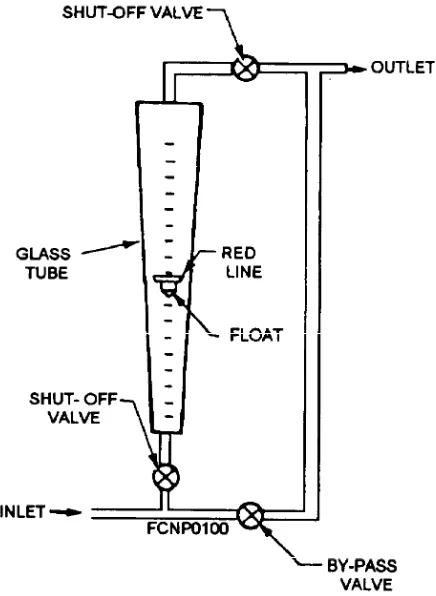
The rotameter (fig. 1-23) is a variable area orifice meter that functions by maintaining a constant differential pressure with varying flow. The rotameter consists of a float positioned inside a tapered, tempered glass tube by the action of the distilled water flowing up
through the tube. The flow restriction is the space between the float and the tube wall. This area increases as the float rises.
The differential pressure is fixed depending upon the weight of the float and the buoyant forces resulting from the combination of float material and the distilled water’s specific gravity. The tapered tube of the rotameter is usually glass with calibration marks reading directly in gpm. The major advantage of a rotameter over the venturi orifice meter is the visibility of the coolant. This allows quick determination of excessive entrained air in the coolant.
CIRCULATING PUMP
Each cooling system has two secondary distilled water circulating pumps (fig. 1-24), which are identical in construction and capacity. One pump is designated for service, and the other is held in standby in case the designated pump fails. Should the pump designated for operation fail, then the standby pump would be used in its place. The pumps should be operated alternately (every other week) to prevent deterioration of their shaft seals, equalize wear, and permit PM actions to be performed regularly.
The two circulating pumps used in the liquid cooling system are single-stage centrifugal pumps closely coupled (pump is built onto the motor) to a constant-speed electrical motor. You may run into an older system that uses a separate pump and motor joined by a flexible coupling. The centrifugal pump has two major elements—the impeller rotating on the extension of the electric motor shaft and a casing that is called the impeller chamber. The impeller imparts the initial
velocity to the coolant. The impeller chamber collects the high-velocity coolant from the impeller and guides it to the pump outlet. A mechanical shaft seal is used to eliminate external leakage. This seal is lubricated and cooled by water ducted from a high-pressure zone of the pump. You will find a vent valve located on the top of the pump casing to remove air and ensure the pump is primed with coolant.
Located at the outlet of each pump is a check valve to prevent coolant from the outlet side of the operating pump from circulating to the return side of the coolant system through the standby pump. Hand-operated valves at the pumps are used to isolate the pumps so they can be removed for maintenance.
Each secondary circulating pump is rated in gallons per minute (gpm) output at a specified head pressure in pounds-force per square inch gauge (psig) pressure, or in feet of water. The rating is usually at the pump’s maximum efficiency point, and it will vary depending upon the pump design. On all pumps, as the output pressure increases, the output flow decreases, and vice versa. This relationship is almost linear but differs with different pump designs. However, this condition means that if a restriction is placed in the pump output lines, the pressure will increase and the flow will decrease. The restriction could be a partially closed hand valve, dirty filter, damaged or crimped piping or hose, and so forth. In figures 1-6, 1-7 and 1-8, the pump performance indicators are the suction and discharge pressure gauges and the system flowmeter. If you start a pump and pressure fails to buildup, you should exhaust air through the vent cock on the top of the pump casing. You should ensure that the suction valve is fully opened and there is
pressure on the pump suction pressure gauge. If flow doesn’t develop, check for clogging and wear.
You should not operate a pump without collant flow. Some pumps have a small recirculating line that enables the pump to recirculate coolant from the discharge side of the pump to the suction side. ‘This provides for a flow of coolant through the pump if an inlet/outlet valve to the pump is closed with the pump running. Whatever the case, you should keep in mind that the operation of a pump without the normal flow of coolant through it will result in overheating and seizure of the pump. Corrective maintenance of the circulating pump consists of repairing leaks, replacement of the mechanical seal, and cleaning the internal parts. This type of maintenance is performed by personnel of the ship’s engineering department. You should provide assistance if it is needed.
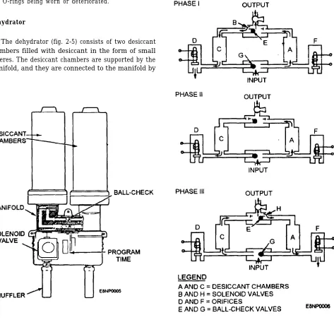
DEMINERALIZER
The secondary cooling system water purity is maintained in an ultrapure state by a demineralizer. By maintaining the coolant at a high degree of purity, you
minimize corrosion and the formation of scale on the radar unit. Corrosion or scale on a high-heat-density component such as waveguide dummy loads and klystrons results in the formation of a thermal barrier. The thermal barrier reduces the effectiveness of heat transfer at normal operating temperatures. This leads to premature failure of the components.
The demineralize (figs. 1-6, 1-7, and 1-8) is connected between the secondary cooling system supply and return lines to circulate water through it. The demineralize is sized so that 5% of the cooling system volume passes through the demineralize every hour. The coolant is purified by organic compound adsorption (if required), oxygen removal, ion exchange processes, and submicron filtration. Shown in figure 1-25 is a typical three-cartridge demineralize. Some demineralizes use only two cartridges; one of the cartridges is a combination cartridge that provides organic compound adsorption, if it is required.
The input supply valve to the demineralize unit, depicted in figure 1-25, must be adjusted on system start-up, and periodically thereafter to maintain the
correct flow rate through the flowmeter. The high of a flow rate can damage the cartridges. If the flow rate cannot be increased to the proper rate with the inlet supply valve fully open, you should check to ensure that the outlet valve is fully open. The submicron filter is used to remove small particles from the coolant flow having a size greater than 0.5 micron. If the filter becomes clogged, it also reduces the flow of coolant. This necessitates a change of the filter cartridge or filter sheet (membrane). To change the filter, the demineralize valves must be properly positioned.
If the filter cartridge or membrane continually becomes clogged (about one-half hour or less after replacement), the usual cause in the distilled water system is the presence of bacteriological impurities, Bacteriological impurities introduced into the secondary liquid cooling system using distilled water may exist in the demineralize cartridges and/or the whole secondary cooling system. If the bacteriological impurities are in the whole secondary cooling system, the growth rate in a warm water environment could be of a magnitude that exceeds the capability of the demineralize. You will have to determine the source and magnitude of contamination. However, it should be noted that bacteriological contamination in a secondary cooling system that uses distilled water and ethylene glycol is highly improbable.
Improper handling or storage of the cartridges could cause the cartridge to be a source of contamination. You should always store the cartridges in a cool, dry area. Exposure to heat hastens the growth of any biological contaminates that may have entered the cartridges. You will encounter three different types of cartridges. The first cartridge is the organic removal cartridge. It contains granulated activated charcoal (carbon) that removes large organic molecules and chlorine by adsorption. It is always installed in the first exchanger (if required) to prevent organic molecules from fouling the remaining cartridges. The second cartridge is the oxygen removal cartridge. It is composed of anion resins that remove oxygen from the water by ion exchange of sulfite ions to sulfate ions. By conducting a standard oxygen test (or if the cooling system has an oxygen analyzer installed), the quality of the outlet water from the demineralize can be tested for oxygen content so that you will know when to replace an oxygen cartridge. When the oxygen cartridge is near exhaustion, it will have a urine odor, which is given off by the sulfate. The third cartridge is the mixed-bed cartridge. It is filled with cation (positive charge) and anion (negative charge) resins, which remove solids, dissolved metals, and carbon dioxide. The charged
resins exchange ions with the contaminates, thereby removing them and leaving pure deionized coolant. You should replace the mixed-bed cartridge when the purity meter indicates a low outlet purity.
As indicated in figures 1-25 and 1-26, two conductivity cells monitor the coolant through the demineralize. The first cell measures the purity of the coolant as it enters the demineralize. The second purity cell is used to measure the purity of the coolant as it leaves the demineralize. The conductivity cell consists of two electrodes immersed in the coolant flow path. The electrodes measure the conductivity of the coolant, which varies with the amount of ionized salts dissolved init. If the impurity content increases in the coolant, the purity meter indicates higher conductance.
On some purity meters, the purity of the coolant is displayed as resistivity. In this type of meter, an increase in the impurity of the coolant causes the meter to indicate a low resistivity. Conductance is the reciprocal of resistance, and is measured in micromhos/cm. Resistivity is measured in megohms/cm. You can convert from conductivity to resistivity by taking the reciprocal of conductivity. Similarly, the reciprocal of resistivity is equal to the conductivity. A comparison of both ways of measuring the purity of the coolant is
shown in table 1-1. The purity meter indications will vary with ionized salt concentration and the temperature of the coolant flowing through the cell. The temperature effect is canceled by a built-in temperature compensation circuit.
The inlet conductivity is compared to a preset value of cell conductance to actuate an alarm circuit when the purity of the water drops below the preset level. In addition, the purity meter provides direct readings of the water purity at the inlet and outlet of the demineralize. Typical operating requirements for the demineralize are conductivity 1 micromno/cm at 77°F (resistivity 1 megohm/cm at 77°F), oxygen content 0.1 ppm by weight, and mechanical filtration 0.5 microns absolute.
When water has been circulated through the system for extended periods of time, a high resistivity or low conductivity reading may be indicated on both input and output samples. This condition is highly desirable and indicates that all ionizable material has been properly treated, and that the demineralize is maintaining a high degree of purity. When a system is filled with a fresh charge of water, it should be allowed to circulate for approximately 2 hours before comparing the input and output readings. During the initial circulation period, the resistivity readings vary because of the mixing action of water that has been treated by the demineralize with the fresh charge of water. A properly operating system can supply water of acceptable purity in 4 to 8 hours. Water in a system that has been secured for any length of time should be of acceptable purity within 2 hours. The resistivity/conductivity reading required for a specific installation must be maintained for optimum operation of the cooling water system.
Your first indication of a problem in the demineralize is usually indicated by abnormal purity meter readings (too low or too high), an abnormal flowmeter reading, and/or a light and audible warning from the purity monitor. Some purity monitors can be tested for accuracy by a built-in test function on
Table 1-1.—Distilled Water Resistivity Versus Conductivity
the meter to establish if the problem is in the purity monitor. If the purity monitor does not have a test feature, then use the calibration plug in place of one of the conductivity cells to test the operation of the purity meter. Most of the time, only routine maintenance is required to return the demineralize to its normal operating condition.
Maintenance of the demineralize consists primarily of the scheduled replacement of cartridges (before they are exhausted) and clogged filters. Obtaining satisfactory service life from the cartridges and filters is largely dependent on minimizing external contamination. Replacement cartridges must be kept sealed and stored in a cool dry place until used. The circulating system must be kept tight to reduce the need for makeup water. Makeup water, in arty case, should be as particle-free as possible and should not exceed 0.065 ppm chloride.
OXYGEN ANALYZER
In some secondary cooling systems, an oxygen analyzer is installed to measure the amount of dissolved oxygen in the liquid coolant. The presence of oxygen causes oxidation that leads to the formation of scale in the cooling system. An oxygen analyzer has an oxygen sensor installed in the supply side of the secondary cooling system. The sensor is an electrolytic cell in an electrolyte solution or gel. A thin membrane covers the end of the sensor, which is inserted in the coolant. This membrane is gas permeable to the dissolved oxygen in the secondary coolant. This allows the oxygen to pass through the membrane. The oxygen reacts with the electrolyte, which causes a proportional change in the amount of current flow in the sensor. The sensor’s electrical output is measured and displayed on the oxygen analyzer’s meter. ‘The meter is calibrated to read the oxygen content in parts per million or billion.
Because of solid-state electronics and the few components used, the oxygen analyzer requires very little maintenance other than the cleaning and changing of the electrolyte in the sensor. When the meter on the analyzer requires frequent calibration because the meter readings are drifting or changing sharply, you should recognize that the analyzer has a bad sensor. When you clean and recharge the sensor, use caution to prevent contamination of the membrane from the oil on your fingers.