Robust Fault Detection of Multilevel Inverter using
Optimized Radial Basis Function based Artificial Neural
Network in Renewable Energy Power Generation
Application
T. G. Manjunath
Sai Vidya Instutute of Technology,
Bangalore,
Karnataka, India
Ashok Kusagur,
PhD
UBDT College of Engineering,
Dhavanagere, Karnataka
India
ABSTRACT
The Optimized Artificial Neural Network based fault detection of the multilevel inverters are of research interest since the HVDC system and Electrical Drives system has started using the multilevel inverters as the power processing units. While the power supply to the multilevel inverters is constant the results of the THD obtained would be stable. But the multilevel inverters that are used with Renewable Energy Resources as the power supply, the variation in the supply would largely affect the THD values thus a robust model for the fault detection of multilevel inverters which not only considers the THD but the positive sequence voltage, negative sequence voltage, zero sequence voltage and angle of the inverter output is considered. This paper is an attempt to develop a robust fault detection method using the optimized Artificial Neural Network (ANN) using the Radial Basis function. The objective function of this optimization algorithm is the minimization of the Mean Square Error while the ANN is getting trained. The optimization is carried out by the use of the weight and the bias value search in the search space, which would enhance the training of the ANN. Particle Swarm Optimization (PSO) and the Cuckoo Search Algorithm (CSA) are considered for the optimization algorithms. Matlab based implementation is carried out and the results are measured and tabulated. It is observed that the CSA algorithm is performing better while training the ANN for the fault detection.
Keywords
Parameter Estimation, Artificial Neural Network, Particle Swarm Optimization, Cuckoo Search Algorithm and Radial Basis Function.
1.
INTRODUCTION
Considering the Total Harmonic Distortion for the fault detection implementation has been successfully analyzed in our previous papers [1-3]. With the frequent use of multilevel inverters in the HVDC systems and electrical drives systems the fault detection of the multilevel inverters would be of utmost importance since there are multiple switches that have to be monitored for faults. An open circuit fault detection system for a 7-level cascaded inverter with Back Propagation based Artificial Neural Network (ANN) is developed with the reconfiguration of the multilevel inverter (MLI) in order to get rid of the fault situation.
The ANN is trained with the Discrete Fourier Transform (DFT) of the output voltage as the parameter inputs with the fault and without the fault in the MLI system. The ANN structure thus developed after the training would be useful in
the prediction of the fault in the MLI. The reconfiguration system would make the inverter work in the desired condition while the fault is predicted in the MLI using the ANN [4]. Various fault modes of the VSI system is investigated for an induction motor drive [5]. Initially, research on fault diagnosis was focused on conventional pulse width modulation including, various fault modes of a VSI system for an induction motor are investigated [5]. The fault detection method with voltage and current detection on the semiconductor device is carried out [6]. Output voltage harmonics is measured to find the fault detection in the cascaded H-bridge Inverter as in [7-8], which suits for the phase shift PWM. Multilevel Inverters controlled by the SVPWM control [9-10]. A medium voltage drive with the cascaded H-bridge is experimented with the fault detection technique. The current waveform of the MLI module is checked for the fault detection in each module [11]. The inverter output and the voltage across each H Bridge are taken as the features in which the variation in the mean values of the measured parameters is used as the fault features. The multilevel inverter working with the Modified Phase Disposition Pulse Width Modulation method experimented using the fault detection method of the 5-level Cascaded MLI is implemented [12]. A current path analysis while the zero voltage switching states is occurring in the MLI with level shifted Pulse Width Modulation (LSPWM) is carried out to obtain the fault detection [13]. Multi-Relevance Vector Machine (mRVM) based classification is carried out with the Principal Component Analysis (PCA) for the feature extraction. This method proved to be highly sparse and fast in detection and response time [14]. A FPGA based implementation of the short circuit fault of the MLI is discussed which needs only one voltage sensor per phase [15]. Balanced three-phase voltage with the desired amplitude of the voltage is maintained by using the auxiliary module of the voltage source inverter with a capacitive dc link. Space Vector Modulation based PWM is generated in order to synthesize the output voltage of the auxiliary inverter to be constant [16]. A model based predictive control implementation is carried out to identify the failed switches and the faults [17]. The DC link with midpoint must be used in which the faulted leg would be connected to the mid point once the fault is detected [18]. The neural network implementation in different applications are discussed in [20-21].
extracted from the multilevel inverters increases the robustness of the fault detection system. In this paper the 7-level multi7-level inverter fault diagnosis with the THD value of voltage is taken as consideration. The total Harmonic distortion (THD), positive sequence voltage negative sequence voltage and zero sequence voltage amplitude and angle are taken for training. The neural network trained with particle swarm optimization and cuckoo search algorithm is compared with the traditional methods like the ANN with Back Propagation. The Section 2 in this paper would discuss about the feature extracted for the implementation carried out, Section 3 discusses different training methods that would be compared, Section 4 elaborates the results and discussion of the simulation carried out on the 7-level Cascaded MLI.
2.
FEATURE EXTRACTION FOR
ROBUST FAULT DETECTION
The consideration that the input voltage of the multilevel inverter would be varying would lead to an idea of robustness to be added in order to improve the accuracy of the fault detection. Thus by the use of multiple feature from the output voltage of the MLI would increase the scope of understanding the output better in order to be able to decide the fault detection accurately. Since it is considered that the PV array is supplied to the MLI the output of the MLI would have variable output thus, in order to detect the fault in these situation would be difficult. Hence multiple features like the positive, negative and zero sequence voltage along with the THD of the output voltage is considered.
As the fault occurring in the MLI in any of the leg would produce an unsymmetrical fault the best way to represent the unsymmetrical fault voltage is to represent it in terms of the positive, negative and zero sequence voltages along with the THD. Thus the features extracted from the output voltage of the MLI are tabulated for different open switch faults introduced in the switches. The training data would comprise the set of the positive, negative and zero sequence voltages and the THD value for the each open switch fault with varying input voltages. The set of data is collected by keeping one open switch fault constant and vary the input voltage from the PV array. The tabulated data thus obtained from the above experiment would be given for training with different algorithms.
3.
NEURAL NETWORK TRAINING
METHOD
Conventionally neural network can be trained with Back-Propagation Algorithm (BPA) technique. But more accurate training can be achieved by using the optimization techniques. In the optimization techniques meta-heuristic methods gives better performance compared to back-propagation method. There are many meta-heuristic methods available. In that particle swarm optimization (PSO), genetic algorithm (GA) and cuckoo search algorithm (CSA) performs better. While training the neuron, weights and bias parameters plays an important role in the accuracy. These algorithms are used to tune the weights and bias value to obtain lesser mean square error (MSE) value. Lesser mean square error value means the training is perfect. If the training is perfect, then the results are accurate. The training methods with algorithm are explained below.
3.1 Radial Basis Neural Network
The radial basis function based neural network is modeled as activation functions as shown in Figure 1. The output of the
neural network is a linear combination of radial basis functions of the inputs and neuron parameters.
Fig.1 Radial basis function neural network structure
No of layers 1) Input layer.
2) Hidden layer and
3) Output layer
Input layer-Source nodes that connect to the network to its environment
Hidden layer-Hidden units provide a set of basis function and High dimensionality
Output layer- Linear combination of hidden functions.
The Neural Network would have the node in any of the layer, which would provide the output, which is the sum of products of the input and the weight values. But when it comes to the radial basis neuron it is the sum of all the difference between the input and the weight value multiplied with the bias value. The Radial basis function is a transfer function, which is an exponential function. The radial basis neuron is given by the formula (1)
A
=
radbas
(
w
-
p
*
b
)
(1)Where A is the output of the neuron node, w is the weight values and p is the values of the input and b is the bias values.The transfer function of radbas is given in the equation (2).
radbas
(
n
)
=
e
-n2 (2)According to the equation (1) and (2) it can be finalized that the function is an exponential function. This is the radial basis function which works in the neuron node of the Radial Basis Function based Neural Network instead of the traditional neural network.
value being the multiplicative adjustment for the neural network training and bias values being the additive adjustment for the neural network training are important for convergence. This adjustment of both the weight and the bias values in a manner to reduce the objective function of RMSE is the algorithm that is carried out in the implementation.
The Pseudo code of the implementation is as shown below,
1. Initialize the weight and the bias values for a particular population like 50 or 100.
2. Using the populated weight and bias values the objective function is found with one iteration of the neural network training for all the populated weight and bias values combination.
3. Then the velocity update function for the optimization algorithm of PSO or CSA (which is used) would find the next weight and bias population for optimization.
4. Continue the process for the number of iteration that is fixed for the optimization algorithm.
5. The velocity update function of the PSO is
v
i(
t
+
1)
=
wv
i(
t
)
+
c
1r
1[
x
Ùi
(
t
)
-
x
i(
t
)]
+
c
2r
2[
g
(
t
)
-
x
i(
t
)]
where
v
i(
t
+
1)
is the new value of the weight orthe bias value ,
x
Ù
i
(
t
)
is the best weight or biasvalue in the current iteration,
c
1 andc
2 areconstants with values near 2,
g
(
t
)
is the weight or bias value which is the global best in all the iteration calculated so far,w
is the inertial coefficient which is a constant.6. The CSA algorithm is inspired by the way the Cuckoo would act as an intruder to the crow‟s nest to lay eggs in the crow‟s nest. The best nest would allow the egg to grow but the worst nest would throw away the eggs. The velocity update function for the CSA algorithm is as given below [19], The probability of the host bird to find the intruder egg is Pa. And the new nest can be found by the following formula,
X
i(
t
+
1)
=
X
i(
t
)
+
a
levy
(
l
)...(3)
whereX
i(
t
+
1)
is the possible solutions ,X
i(
t
)
is the previous solution,a
is the step size which controls the amount of search scale, is the number of nest that has to be abandoned in the current iteration. The Cuckoo would lay the eggs by a randomness of the Levy Flight, which is defined by the following function,levy
(
l
)
= G
(1
+
l
)
´
sin(
P
l
/ 2)
G
((1
+
l
) / 2)
´
l
´
2
((l-1)/2)1/l
where
l
is a constant (1<l
£
3) andG
is the gamma function which is defined by the integral value ,G
(
x
)
=
e
-t0
¥
ò
t
x-1dt
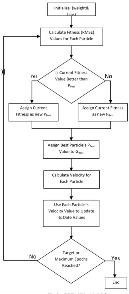
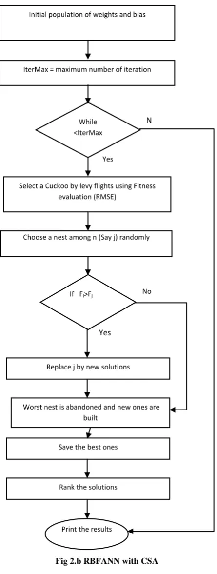
The fig.2a shows the flow chart of RBF neural network training with PSO algorithm. The fig.2b shows the flow chart of RBF neural network training with CSA algorithm. The input and target is given to the INITFF (built-in Matlab function) to generate the initial values of weights and bias. With RBF find the mean square error after training.
[image:3.595.310.537.225.740.2]Then pass this weights and bias tocuckoo search to obtain the new and best value by using the „x‟ variable update (different formulas for PSO & CSA as given in fig 2a, Fig 2b. Repeat the procedure till the end of iterations reached.
Fig 2.a RBFANN with PSO
Initialize (weight& bias)
Calculate Fitness (RMSE) Values for Each Particle
Is Current Fitness Value Better than
PBest
Assign Current Fitness as new PBest
Assign Current Fitness as new PBest
Assign Best Particle’s PBest Value to GBest
Calculate Velocity for Each Particle
Use Each Particle’s Velocity Value to Update
its Date Values
Target or Maximum Epochs
Reached?
End
Yes
No
Fig 2.b RBFANN with CSA
4.
SIMULATION AND RESULTS
During the training phase of the MLI is supplied with the different PV array voltages and the due to that the variation observed from each switch failure. The plots of the positive sequence, negative sequence and the zero obtained during different open switch fault with the variable PV array input is given as shown in the figures below.
[image:4.595.306.545.84.632.2], and are the positive, negative and zero sequence voltage of the inverter output in the faulted condition.
Fig 4. Positive Voltage Sequence Fig 5. Zero Voltage Sequence
Figure 5. Negative Sequence Voltage
Figure 6. Zero Sequence Voltage
Initial population of weights and bias
IterMax = maximum number of iteration
While <IterMax
Select a Cuckoo by levy flights using Fitness evaluation (RMSE)
Choose a nest among n (Say j) randomly
If Fi>Fj
Replace j by new solutions Yes
N o
Worst nest is abandoned and new ones are built
Save the best ones
Rank the solutions
Print the results
No
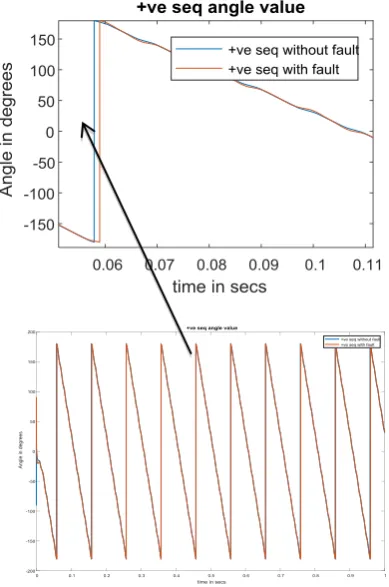
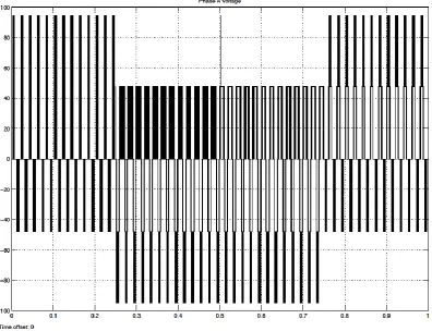
Fig 7. Positive Sequence Phase with and Without fault
𝑣1=
1
3∗ 𝑉𝑎+ 𝑎 ∗ 𝑉𝑏+ 𝑎
2∗ 𝑉
𝑐
𝑣2=
1
3∗ 𝑉𝑎+ 𝑎
2∗ 𝑉
𝑏+ 𝑎 ∗ 𝑉𝑐
𝑣0=
1
3∗ 𝑉𝑎+ 𝑉𝑏+ 𝑉𝑐
Where,
𝑎 = exp 𝑗 ∗ 2 ∗𝜋 3
Figure.10 is the important graph, which depicts the instantaneous THD value of the inverter at different switch failure. The THD values of Q1, Q2, Q3 and Q4 faulted at each 0.25 sec respectively is depicted. Algorithm discussed in the Section 3 is applied on the fault detection of the Mutltilevel Inverter system. The training of the ANN for the fault detection is the major portion of the experiment. The performance of training the ANN with different PSO and CSA technique is evaluated in order to apply the algorithm on a hardware implementation. Thus the hardware implementation of the algorithm needs a feasibility.
[image:5.595.65.260.75.369.2]Figure 8. THD in Multilevel Inverter
Fig 9. Zero Sequence Phase with and Without fault
study by means of speed of execution of the algorithm while training and testing the fault detection system. The comparative analysis of the Mean Square Error of the different algorithms with different iteration number is given in Table.1
Table 1. Execution time each iteration
Run no. BPA
ANN with PSO
ANN with GA
RBFAN N with PSO
BFANN with CSA
1
3.2189E-09
6.1979E-12 0.0287
2.11E-28 6.64E-29
2 0.2314 0.0165 0.0378
1.44E-28 7.13E-29
3 3.51E-09 0.9218 0.0385
1.03E-28 1.47E-28
4 0.3826 4.04E-05 0.0398
1.02E-28 6.38E-29
5 2.38E-08 2.52E-09 0.034
[image:5.595.54.231.403.511.2]
6
1.9757E-08
3.1857E-10 0.0398
2.11E-28 1.13E-28
7 2.53E-08 5.79E-09 0.0337
7.12E-29 8.74E-29
8 0.2171 9.03E-04 0.0394
1.84E-28 7.11E-29
9
4.6541E-06
3.7917E-08 0.0351
1.04E-28 7.11E-29
10 0.3313 1.26E-06 0.0378
9.04E-28 8.36E-29
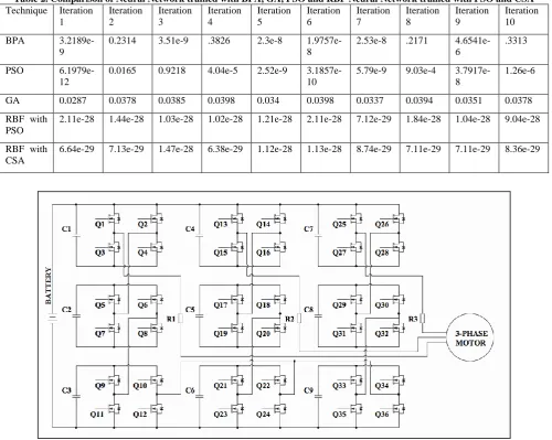
From the above results it can be seen that the radial basis function is used to reduce the mean square error (10-29). Here the back-propagation is minimizing better, but if it is trained for more number of times like 10 runs the values are changed thus reflecting inaccuracy and it is also depicted in the graph shown in Figure 11. Similar problem is confronted while PSO is used. Hence RBF is used in neural network and trained with PSO to reduce the mean square error. And it gives the error value very less, approximately zero By using cuckoo search algorithm, the error minimizes to zero consequently more accurate than PSO. So RBF neural network trained with cuckoo search algorithm is performing better comparatively. The same is indicated in fig.11. The fig.12 shows the voltage waveform at Q1, Q2, Q3 and Q4 faulted at each 0.25 sec. So this THD value is given as input and target is used as the switch number 1 to 4 in each 0.25 sec. After learning using this faults can be identified and remedial actions can be taken.
5.
CONCLUSION
The proposed robust method of fault diagnosis is applied on the 7 level MLI with Back Propagation ANN, Genetic Algorithm , PSO optimized ANN and CSA optimized ANN. The neural network while training uses minimization of the mean square error (MSE) as the objective function. Even if there is a variation in the input voltage due to PV supply the robustness of the algorithm due to multiple features introduced had helped to detect faults efficiently. The cuckoo search algorithm with radial basis function gives better results comparatively by means of training time and prediction time. The neural network trained with BP, GA and PSO, gives lesser MSE but radial basis function based neural network gives better performance compared to all the other methods used for training.
6.
REFERENCES
[1] T.G.Manjunath, Dr.Ashok Kusagur “Fault Diagnosis and Reconfiguration of Multi level Inverter switch failure- A performance perspective ” , International Journal of Electrical and computer Engineering.,vol.6,no.6, Dec 2016,pp.2610-2620
[2]T.G.Manjunath, Dr.Ashok Kusagur, “ Multilevel Inverter Fault Diagnosis using optimized Radial Basis Neural Network –A Novel performance Enhancement ”, IEEE International Conference of Electrical, Electronics , communication, computer and optimization Techniques Systems (ICEECCOT), Jan. 2017.
[3] T.G.Manjunath, Dr.Ashok Kusagur, “Performance Evaluation of Modified Genetic Algorithm over Genetic Algorithm Implementation on Fault Diagnosis of Cascaded Multilevel Inverter”, IEEE 2015 International Conference on Conditioning Assessment Techniques in Electrical Systems (CATCON), CPRI, Bangalore, Dec. 2015.
[4] Wei Jiang et al,” Fault Detection and Remedy of
Multilevel Inverter Based on BP Neural Network”,IEEE 2012,Power and Energy Engineering Conference (APPEEC), Shanghai, China, Mar. 2012.
[5] D. Kastha and B. K. Bose, “Investigation of fault modes of voltage-fedinverter system for induction motor drive,” IEEE Trans. Ind. Appl., vol.30, no. 4, Jul. 1994, pp. 1028–1038.
[6] Wenchao Song, Alex Q. Huang, “Fault Tolerant Design and Control Strategy for Cascaded H-bridge Multilevel Converter based STATCOM” IEEE Trans. Ind. Electron., vol.56,no.6,June 2009, pp.2275-2283.
[7] Pablo Lezana, Ricardo Aguilera, and José Rodríguez, “Fault Detection on Multicell Converter Based on Output Voltage Frequency Analysis”, IEEE Trans. Ind. Electron., vol.57,no.8,June 2009, pp.2700-2708.
[8] Frédéric Richardeau, Philippe Baudesson, Thierry A. Meynard,“Failures-Tolerance and Remedial Strategies of a PWM Multicell Inverter” IEEE Trans. Of Power Electronics., Vol.17 ,no.6,June 2000, pp.905-912.
[9] Ho-In Son , Tae-Jin Kim, Dae-Wook Kang and Dong-Seok Hyun “Fault Diagnosis and Neutral Point Voltage Control When The 3-Level Inverter Faults Occur”,2004 IEEE 35th Annual Power Electronics Specialists Conference (PESC),Nov 2004.
[10] Shengming Li, Longya Xu, “Strategies of Fault Tolerant Operation for Three-Level PWM Inverters” IEEE Trans. Power Electronics., Vol.21, no.4, Oct, 2005, pp.933-940.
[11] Kalpani Thantirige et al “An open-switch fault detection method for cascaded H-bridge multilevel inverter fed industrial drives”, 2016 IEEE 42nd Annual Conference of the Industrial Electronics Society (IECON), Florence, Italy ,2016.
[12] A. Anand, N. Raj, S. George and Jagadanand G, "Open switch fault detection in Cascaded H-Bridge Multilevel Inverter using normalized mean voltages”, 2016 IEEE 6th International Conference on Power Systems (ICPS), New Delhi, India, 2016, pp. 1-6.
[13]Hyun-Woo Simet al,”Detecting Open-Switch Faults: Using Asymmetric Zero-Voltage Switching States”, IEEE Industry Applications Magazine .,Vol. 22, no. 2, March-April 2016 , pp.27-37
[14] Tianzhen Wang et al, ”Cascaded H-Bridge Multilevel Inverter System Fault Diagnosis Using a PCA and Multiclass Relevance Vector Machine Approach” IEEE Trans. on Power Electronics., Vol. 30, no. 12, Dec. 2015, pp.7006 – 7018.
[15] M Shahbazi, M. R. Zolghadri, P. Poure, and S. Saadate, “Fast short circuit power switch fault detection in cascaded H-bridge multilevel converter,” in Proc. IEEE Power and Energy Society General Meeting (PES), July 2013, pp.1,5, 21-25.
[16]Houshang Salimian et al ”Fault-Tolerant Operation of Three-Phase Cascaded H-Bridge Converters Using an Auxiliary Module”, IEEE Trans. Ind. Electron., Vol. 64, no.2, Feb. 2017
[18] J. Druant, T. Vyncke, F. D. Belie, P. Sergeant, J. Melkebeek, “Adding Inverter Fault Detection to Model-Based Predictive Control for Flying-Capacitor Inverters,” IEEE Trans. Ind. Electron., vol. 60, no. 4, Aprl. 2015, pp.2054-2063.
[19] Rajabioun, Ramin. (2011). “Cuckoo Optimization Algorithm”. Applied Soft Computing. 11. 5508-5518. 10.1016/j.asoc.2011.05.008
[20] A Kusagur, SF Kodad, BVS Ram,” Modeling, design & simulation of an adaptive neuro-fuzzy inference system (ANFIS) for speed control of induction motor”, International Journal of Computer Applications 6 (12), 29-44,2010
[image:7.595.49.550.189.588.2][21]Ashok Kusagur, ”Design and implementation of Neuro fuzzy based speed control of induction motor drive by space vector pulse width modulation for voltage source inverters”, 2011.
Table 2. Comparison of Neural Network trained with BPA, GA, PSO and RBF Neural Network trained with PSO and CSA
Technique Iteration 1
Iteration 2
Iteration 3
Iteration 4
Iteration 5
Iteration 6
Iteration 7
Iteration 8
Iteration 9
Iteration 10
BPA
3.2189e-9
0.2314 3.51e-9 .3826 2.3e-8 1.9757e-8
2.53e-8 .2171 4.6541e-6
.3313
PSO
6.1979e-12
0.0165 0.9218 4.04e-5 2.52e-9 3.1857e-10
5.79e-9 9.03e-4 3.7917e-8
1.26e-6
GA 0.0287 0.0378 0.0385 0.0398 0.034 0.0398 0.0337 0.0394 0.0351 0.0378
RBF with PSO
2.11e-28 1.44e-28 1.03e-28 1.02e-28 1.21e-28 2.11e-28 7.12e-29 1.84e-28 1.04e-28 9.04e-28
RBF with CSA
6.64e-29 7.13e-29 1.47e-28 6.38e-29 1.12e-28 1.13e-28 8.74e-29 7.11e-29 7.11e-29 8.36e-29
Fig 11. Comparison between Neural network trained BPA, PSO, GA, RBF neural network trained with PSO and CSA
[image:8.595.100.497.330.634.2]