Experimental Study on Local Scour in the Downstream
Area of Low Drop Structure Types
Changsung Kim, Joongu Kang, Hongkoo Yeo
Department of Water Resource Research, Korea Institute of Construction Technology, Ilsan, Korea Email: [email protected], [email protected], [email protected]
Received May 16, 2012; revised June 15, 2012; accepted June 26, 2012
ABSTRACT
Although ecologically disadvantageous since a river is interrupted because of drop structure installation, such structure installation is also deemed ecologically advantageous in terms of scour and complex flows in the direct downstream area. This study started from the premise that scour hole carries value as a habitat and sought to analyze quantitatively the local scour adjustment possibility in the downstream area through drop structure type change and to offer a habitat through scouring. This study provided changes in drop structure types, such as straight line type and V type. For local scour analysis impacting the downstream area by drop structure type, quantitative analysis of scour scope, depth, and length was comparatively performed for a tentative physical habitat through hydraulic experiments. As a result of the experiments, this study found that scour scope increases and various water depth conditions are offered as the angle of the drop structure’s apex becomes smaller. Future studies accompanied by various fish habitation evaluations are con- sidered useful in finding an alternative to upgrade the ecological environment.
Keywords: Low Drop Structure; Local Scour; Physical Habitat; Scour Size
1. Introduction
The stability of a natural river depends on the bed slope, silt movement, state of natural ground, depth of low wa- ter channel, structure of channel and riverside and river- side vegetation. Among these, bed slope is the most im- portant factor; thus, a method of properly maintaining bed stability should be sought (H. J. Kim et al. [1]). For the natural river’s stability, installing mainly riverbed maintaining facilities is a universal practice. The drop structure as a typical structure of riverbed maintaining facilities is a type of river cross-cutting structure installed to prevent bed scour and erosion at the steep slope of the channel. The drop structure is generally defined as a structure with sharp fall of 0.5 m or more. In Korea, in- stalling scour protection structure in the apron and down- stream area is a universal practice to prevent scouring in the downstream area, whereas most bodies and apron are installed as single concrete structure (River Design Standard [2]).
The installation of such drop structure is designed and constructed in line with the installation purpose of secur- ing bed stability based on the river design standard; al- though effective for channel stability, it is known to cause various ecological and environmental damages such as interruption of the channel environment’s conti- nuity (H. J. Kim et al. [1]). As a typical example, a river
cross-cutting structure at high altitude disrupts the mi- gratory fish’s movement between the upstream and down- stream areas of a river and reduces the number of fish and diversity of fish species. Moreover, some fish can become extinct (Ministry of Environment, MOE [3]). To overcome such demerit, continued efforts have been made toward using natural materials for the body and au- xiliary structures of a drop structure or reducing eco- logical and environmental damages by installing fishway at the body of the drop structure, with some achieve- ments. Note, however, that the supplementary methods proposed to date have not presented a fundamental solu- tion. To solve the ecological and environmental problems caused by the installation of cross-cutting structures in- cluding drop structures, understanding of the living things inhabiting the river in question is essential. Based on such understanding, a most effective method may be installing cross-cutting structures through which fish living in the river in question can easily move.
drop structure, functions as a fish habitat. Note, however, that they did not present specific habitat evaluation and standard on the size of scour hole (scope, depth, etc.) according to the drop structure. Even though some study achievements have been presented in Korea including the suggestion of low drop structures using huge stones to secure an effective fish habitat environment, they simply presented the standard on the structure’s stability. Those studies merely mentioned that the effect of fish habitat improvement is in the early stages, i.e., citing only water quality improvement (MOE [3]).
The evaluation on the habitat improvement effect in the downstream area of drop structures can be performed through habitat simulation. The study on habitat began in developed countries including the US and Europe in the 1970s. In Korea, the concept of river maintaining flow considering the fish was adopted only in the latter part of the 1990s, and various studies have been conducted since then (D. G. Lim et al. [6]). Since the 2000s, various types of natural-type drop structures have been suggested to improve the habitat of fish as part of river restoration efforts and have been applied to actual problems. Note, however, that the studies to date merely present a com- prehensive, conceptual result i.e., the physical habitat can be improved by complex flow through the installation of boulder or embankment within the channel. Actually, systematic and specific studies are insufficient.
This study started with the premise that a scour hole has value as habitat and sought to analyze local scour adjustment possibility in the downstream area through drop structure type change and to offer habitat through scour in the future. Various types of scour holes includ- ing straight and V shapes were used in this study, and quantitative comparison for a tentative physical habitat was carried out by evaluating the scour effect on the downstream area of the channel in question. As for the structure in question, a low drop structure with drop height where fish for simulation can ascend was selected, and a wood drop structure that was environment-friendly and easily acquired was the object of this study. This study conducted hydraulic experiments to check the scour effect downstream according to the drop structure type.
2. Existing Studies
Scour in the downstream area of drop structures is caused by plunging jet generated by the drop of flow passing through the drop structure. The flow passing through the drop structure shows a type of free over fall and a com- plex flow type in the riverbed downstream due to plung- ing jet. The study on scour in the downstream area of drop structures generated by complex flow characteris- tics was conducted by Schokiltsh [7], Veronese [8], Zim-
merman and Maniak [9], Bormann and Julien [10], Fahl- busch [11], Hoffmans [12], Federal Highway Admini-stration (FHWA) [13], and Construction Industry Re-search and Information Association (CIRIA) [14]. Scho- kiltsh [7] derived an empirical equation by performing indoor experiments under the condition of similar free fall. This equation has a limitation, i.e., it does not con-sider the height of the drop structure, and applies to the experiment with height difference of 0.06 m and 0.32 m between the upstream and downstream areas. Veronese [8] carried out an evaluation on the scour depth caused by the low water head’s waterspout in the down-stream area of riverbed protection structures and suggested in FHWA [13]. Note, however, that other equations predict scour depth with only total head loss or water depth in the inlet and downstream area unlike the equation de-rived as the relation between particle movement and ve-locity. Bed materials are not reviewed, with the scour depth estimated to be relatively excessive. Zimmerman and Maniak [9] suggested an equation to estimate the scour depth formed in the floor protection structure in the drop structure waterspout, which is the same location in the equation of Veronese [8]. Bormann and Julien [10] proposed an equation of scour depth formed in the downstream area of the slope-type drop structure. As for the equation application scope, from 0.3 m2/s to 2.5 m2/s
of flow per width, the limit of maximum scour depth derived through calculation is 1.4 m. The equation of Fahlbusch [11] theoretically approaches shearing stress and drag and lift equilibrium and resistance. This equa-tion suggests that scour depth decreases as water depth and flow decrease, whereas scour depth decreases as downstream depth increases. The limitation of such ap-plication is that considering various variables is neces-sary including sediment size, sediment size distribution, sediment shape, silt density, material’s viscosity, and turbulence level since the equation deals only with the equilibrium of strength, given the fact that various phy- sical variables are associated with silt’s marginal move-ment. Hoffmans [12] derived an equation with the non- dimensional scour variable associated with riverbed sedi- ment size ( 90) by supplementing the proposed equation of Fahlbusch [11] through the application of the -theo- rem in 2v. In case of
d
π
c d900.0125 m,
applies. In case of , 90 applies.
25 m
d
2v2.9 0.01 900.0125 m c
d
In case of d900.0125 m and
2
1/3* 90
90 g
d d
and 1.65 given, kinematic viscosity . This equation was adopted as the scour evaluation equa-tion in the drop structure waterspout in CIRIA [14].
6 2 10 m /s
3. Hydraulic Model Experiment
type low drop structure was an experimental channel with length of 30 m, height of 1.2 m, and width of 3.0 m. The experimental channel was installed to supply precise flow through the square weir located upstream; a width- wise laying sluice gate was installed to control the water level in the downstream area of the channel. The drop structure as the experiment object was installed at the center of the channel to check the riverbed change scope downstream. A 3.0 m open channel having the same width as an actual small channel width was used so that physical habitat evaluation could be performed according to fish type in addition to scour analysis. Concerning water level control downstream, as a result of the review of the experiment study carried out by C. S. Kim et al.
[15] regarding scour in the downstream area of the verti- cal drop structure and scour protection structure subsi- dence, maximum scour depth was noted in the minimum condition of water depth in the downstream area of the vertical drop structure. Therefore, this study also con- ducted experiments in a state of no artificial control of downstream water level, i.e., in outflow condition. Fig- ure 1 show the structure and flow supply device located
at the center of the channel in the experimental channel where scour experiments were performed.
The size of the drop structure used in the experiment targeted a low drop structure with height of 0.5 m or less, which was close to the actual situation. Even though the experiment was carried out in a lab, efforts were made so that the experiment was as free as possible from the issue of the similitude law according to scale. The hydraulic experiment carried out in this study consisted of wood with diameter of 0.1 m, targeting a natural-type low drop structure with height of less than 0.5 m.
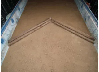
This study adopted the straight line type (180˚) and upward V-type as drop structure types, with three angles adopted for the V-type. Figure 2 shows the drop struc-
ture types. The straight line type is a drop structure that is easily found in a river, whereas the upward V-type tends to be applied more in foreign countries than in Korea. Various studies have been conducted for the straight line type, and reliable results have been presented. Note, however, that effective study results are insufficient,
[image:3.595.307.537.85.165.2]Figure 1. Experimental flume.
Figure 2. Low drop structure types for the experiment.
except studies on the scour of some varied types (laby- rinth weir) in the case of the V-type drop structure.
Table 1 shows the experiment conditions. The drop
structure in question comes in 4 types whose upward angle (θ) was changed to 180˚, 140˚, 100˚, and 70˚ as
shown in Figures 1 and 2. The drop structure conditions
are H180, H140, H100, and H70, respectively, in this study, and H180 means a straight line type. Only the up- ward V-type was considered in this study because ero- sion can occur at the shore in the case of natural river, since scour can be generated on the left and right sides of the downstream area of the structure owing to overflow of the drop structure in the case of the downward V-type (θ > 180˚). Moreover, the downward-type drop structure
was excluded from the experiment object because the scour type could be distorted owing to the wall impact of the experimental channel.
[image:3.595.92.252.602.719.2]4. Experimental Results and Discussion
Table 2 shows the scour experiment results in the down-
stream area, which change according to the drop struc- ture types. When the drop structure assumed a horizontal type, experiments were performed by changing only the angle of the drop structure’s apex without lateral slope to see the scour of the drop structure according to the drop structure types. The scour effect in the downstream area of the drop structure was indicated by apex angle with regard to scour depth and length, and the measurement results on the topographical change downstream were presented. Looking into the change according to the drop structure types, each angle of the drop structure’s apex was set at 180˚, 140˚, 100˚, and 70˚, respectively, by structure type; topographical change in the downstream area of the drop structure was measured according to 0.01 - 0.04 m2/s flow per unit width. Here, for scour
Table 1. Experimental case.
Type Unit Discharge (m2/s) Inflow Depth (m) Tail-Water Depth (m) Angle of Apex (˚) Remark
H180V00(1) 0.01 0.120 0.040
H180V00(2) 0.02 0.142 0.055
H180V00(3) 0.03 0.150 0.070
H180V00(4) 0.04 0.160 0.085
180
H140V00(1) 0.01 0.120 0.040
H140V00(2) 0.02 0.130 0.050
H140V00(3) 0.03 0.150 0.070
H140V00(4) 0.04 0.160 0.085
140
Exceed the floor height
H100V00(1) 0.01 0.115 0.040
H100V00(2) 0.02 0.135 0.055
H100V00(3) 0.03 0.140 0.070
H100V00(4) 0.04 0.147 0.085
100
H070V00(1) 0.01 0.110 0.040
H070V00(2) 0.02 0.120 0.055
H070V00(3) 0.03 0.130 0.070
H070V00(4) 0.04 0.140 0.085
70
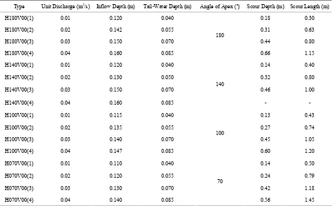
Table 2. Experimental results with horizontal variations of structure layout.
Type Unit Discharge (m2/s) Inflow Depth (m) Tail-Water Depth (m) Angle of Apex (˚) Scour Depth (m) Scour Length (m)
H180V00(1) 0.01 0.120 0.040 0.18 0.30
H180V00(2) 0.02 0.142 0.055 0.31 0.63
H180V00(3) 0.03 0.150 0.070 0.44 0.80
H180V00(4) 0.04 0.160 0.085
180
0.66 1.15
H140V00(1) 0.01 0.120 0.040 0.14 0.40
H140V00(2) 0.02 0.130 0.050 0.32 0.80
H140V00(3) 0.03 0.150 0.070 0.46 1.00
H140V00(4) 0.04 0.160 0.085
140
- -
H100V00(1) 0.01 0.115 0.040 0.13 0.43
H100V00(2) 0.02 0.135 0.055 0.27 0.74
H100V00(3) 0.03 0.140 0.070 0.45 1.05
H100V00(4) 0.04 0.147 0.085
100
0.60 1.20
H070V00(1) 0.01 0.110 0.040 0.14 0.50
H070V00(2) 0.02 0.120 0.055 0.24 0.79
H070V00(3) 0.03 0.130 0.070 0.42 1.18
H070V00(4) 0.04 0.140 0.085
70
0.56 1.45
[image:4.595.57.540.435.734.2]Sl was measured based on the drop structure. In the case of the straight line drop structure, application is possible without another definition since the structure is of the straight line type. Note, however, that very complex to- pography is formed depending on the structure type in the case of a V-type drop structure. Therefore, Sl was defined as the length measured at the center of the drop structure so that comparison can be done at the same location.
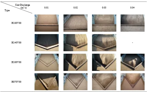
Table 3 shows the scour types in the downstream area
according to the drop structure types. In H180V00 condi- tion, scour was generated as a straight line drop structure type in the downstream area with regard to the scour type downstream. From low- to high-flow conditions, scour depth and length tended to show an uptrend; such phe- nomenon is the same type of scour in the downstream area of general drop structures that have been dealt with extensively as the existing study case. In H140V00 con- dition, i.e., under the condition of drop structure with angle of 140˚, as local flow gradually increased, the scour amount in the central part increased. Maximum scour depth was formed in the center of the direct down- stream area of the structure. Under the condition of H100V00, scour was gradually concentrated on the chan- nel center in terms of local scour as flow increased. Un- der flow condition of 0.03 m2/s or more, not only scour
in the direct downstream area but also sedimentation and
scour downstream were generated. The center located in between the downstream area of drop structures was judged to show more sedimented shape compared to the left and right sides because of the complex flow type wherein the flows on the left and right inside the channel are interrupted by each other as overflow falls over the drop structure. As a peculiar phenomenon, secondary scour was generated on the left and right sides of the downstream area of the structure. This is also interpreted to mean that whirlpools are interrupted by each other due to the plunge on the left and right sides of the structure. Under the experimental condition of H070V00, the cen- ter of the scour area increased as flux increased in terms of local scour; at 0.02 m2/s. scour was concentrated on
the center of the drop structure downstream. In addition, the central part of the drop structure downstream showed less scour compared to other locations because of the interruption of overflow to the left and right sides of the structure.
As for the scour type in the downstream area of the drop structure, according to the drop structure types, scour holes were evenly distributed over the entire struc-ture in the case of the straight line-type drop strucstruc-ture. Note, however, that scour changed according to the change of angles of the drop structure’s apex, and water flow concentrated on the central part by overflow as the angle of the drop structure’s apex decreased. The water
Table 3. Scour shapes in the experimental cases.
Unit Discharge (m2/s)
Type
0.01 0.02 0.03 0.04
H180V00
H140V00 -
H100V00
flow concentrated on the center becomes a factor that increases local scour in the central part, but whirlpool caused by scour wields the effect of reducing scour on the left and right sides owing to interruption at the central part by each other.
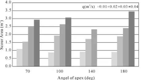
This study confirmed that the scour types in the down- stream area of the drop structure were different from the existing vertical drop structure (H180V00) in the case wherein the angle of the drop structure’s apex changes. In other words, the change of angle of the drop structure will bring about change in local scour scope, depth, and length. Such spatial change can become an important factor in habitat size estimation, since scour holes are related to the habitat. The drop structure in this study was based on conditions considering the habitat; thus, this study spatially analyzed the experiment results. Figure 3
shows the scope of influence of scour according to the drop structure types. As for the calculation method of area, the scour area in the downstream area of drop structures was analyzed and calculated using the topo- graphical measurement data and photo data in the down- stream area of each drop structure. When flow was 0.01 m2/s per unit width, an almost similar area was recorded.
As flow per unit width increased, however, different characteristics were exhibited. When flow was 0.02 - 0.03 m2/s per unit width, the angle of the drop structure’s
apex showed maximum value at 100˚. Meanwhile, when
flow was 0.04 m2 per unit width, the angle of the drop
structure’s apex showed maximum value at 180˚. The
difference of scour area was believed to stem from dif- ferent scour types according to the change of angle of the drop structure’s apex.
Figure 4 illustrates the change of maximum scour
depth. The criteria factors of habitat are velocity of flow, water depth, and riverbed materials. For maximum scour depth, water depth can be considered among the habitat criteria. According to the angle of apex, different scour depths were confirmed in this study. Looking into each hydraulic condition, as flow per unit width increased, scour depth increased. In the same flow condition, as the angle of apex increased, the maximum scour depth changed in this study. Here, when flow was 0.01 m2/s per
unit width, the difference in the maximum scour depths’ effect on the angle of apex was minimal, possibly due to the fact that enough scour did not develop in the down- stream area of drop structures. Meanwhile, the trend could be clearly seen in the flow condition of 0.02 m2/s
or more. Here, when flow was 0.04 m2/s per unit width,
scour depth was formed beyond 0.7 m as the experiment channel’s installation height downstream and under the condition of 140˚ apex angle. Note, however, that the
same minimum value was recorded in all flow conditions when the angle of apex was 70˚ except the condition of
[image:6.595.310.539.87.218.2]0.01 m2/s. As the angle increased, scour depth gradually
Figure 3. Scour area with different angle of the drop struc- ture’s apex.
Figure 4. Scour depth with different angle of the drop struc- ture’s apex.
increased, reaching a maximum of 140˚; at 180˚, i.e., in
the straight line drop structure type, scour depth tended to decrease. In the case of 180˚, scour was formed by
overflowing running water, and scour depth tended to increase gradually due to the running water’s interaction as the angle of apex decreased while scour was generated by simple overflowing running water power. Note, how- ever, that secondary scour was formed downstream and within the angle of 140˚. Actually, the overflows inter-
rupt each other in the downstream area of drop structures, and scour tends to decrease relatively.
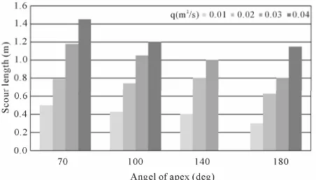
The scour length was measured based on the struc- ture’s center. In the case of the straight line-type hori- zontal drop structure (H180V00), the same scour was formed in the entire structure. In other words, the same scour depth was formed over the structure’s width, and the scour length also showed almost similar values. When the drop structure’s type changed, however, the scour hole showed a different type from the straight line type as can be confirmed through the experiment results. Consequently, this study measured the maximum scour length focusing on the central part of each drop structure; this was defined as the maximum scour length. Figure 5
[image:6.595.312.537.258.385.2]Figure 5. Scour length with different angle of the drop struc- ture’s apex.
In terms of scour depth, the maximum scour depth was confirmed to have been formed in a specific angle, but the scour length differed by angle of apex under each flow condition. When flow was 0.01 m2/s and 0.02 m2/s
per unit width, an almost similar scour length was re- corded from 70˚ to 140˚; at 180˚, i.e., in the straight line type, the minimum scour length was observed. When the flow was 0.03 m2/s per unit width, however, the maxi-
mum value was recorded at 70˚, and scour length gradu- ally declined as the angle of apex rose. This trend’s effect on the angle of the drop structure’s apex was minimal under low flux condition; its effect on the downstream area increases in many conditions. As the angle of apex diminished, the flow passing through the drop structure was concentrated on the channel’s central part, and scour length was believed to increase through interruption be- tween overflows.
The ratio of scour length/maximum scour depth means the scour hole’s slope; the ratios were compared to infer the scour hole’s type. Figure 6 shows the relationship
between the change of angles of the structure’s apex and the non-dimensional ratio of scour length/scour depth in the downstream area of drop structures. The ratio of Sl/ Sd showed a decline as the angle of the drop structure’s apex increased, and the correlation was very high. When the flow was 0.02 m2/s per unit width, Sl was about 3
times larger than Sd at 70˚; as the angle increased, how- ever, Sl was about 2.7 times, 2.5 times, and 2.0 times larger than Sd at 100˚, 140˚, and 180˚ (straight line), re- spectively. When the angle of apex increased under the condition of the same scour depth, the scour size in- creased, and various water depths condition could be demonstrated. Consequently, the change of angles of the drop structure’s apex is believed to adjust the conditions of various scour sizes and various scour depths when the habitat is considered.
5. Conclusions
[image:7.595.60.286.87.216.2]This study analyzed scour change wherein natural mate-rials were used and river cross-cutting structure over
Figure 6. Relationship between Sl/Sd and angle of apex with the drop structure.
which fish could ascend affected the downstream area as well as the physical environmental effect due to topog- raphical change downstream. The installation of natural- type low drop structures is expected to reduce the envi- ronmental damages of the previous cross-cutting struc- tures and improve the ecological environment. The eco- logical evaluation of scour holes was performed quanti- tatively in the past, but this study quantified the evalua- tion through hydraulic and large-scale channel experi- ments.
Regarding the scour types in the downstream area of drop structures, according to the drop structure type, this study confirmed that scour holes were evenly distributed in the entire structure in the case of the straight line drop structure. Note, however, that scour changed according to the angles of the drop structure’s apex, and that water flow was concentrated on the center by overflow as the angles of the drop structure’s apex decreased. The water flow concentration on the center became a factor in in-creasing local scour.
Under the condition wherein the same scour depth was formed, this study found that scour size increased, and that various depth conditions were observed as the apex angle increased. Therefore, when the fish habitat is con-sidered, the various angles of the drop structure’s apex are believed to adjust the various size and depth condi-tions. The various types of drop structures are considered useful as an alternative in improving the ecological envi- ronment through studies accompanied by various fishes’ habitat evaluation in the future.
6. Acknowledgements
This study was supported by the Internal Research Pro- ject of “River Structure Design Techniques for Harmo- nizing Nature with the Human” in KICT.
REFERENCES
Alternative of Ecological Growth with River Crossing Structure,” The Magazine of the Korean Society of Civil Engineers, Vol. 51, No. 3, 2003, pp. 42-58.
[2] Korea Water Resource Association, “River Design Stan- dard,” Korea Water Resource Association, Seoul, 2009. [3] Ministry of Environment, “Development of Close-to-Na-
ture River Improvement Techniques Adapted to the Ko-rean Streams,” Korea Institute of Construction Technol-ogy, Seoul, 2002.
[4] C. M. Cooper and S. S. Knight, “Fisheries in Man-Made Pools below Grade-Control Structures and in Naturally Occurring Scour Holes of Unstable Streams,” Journal of Soil and Water Conservation, Vol. 42, No. 5, 1987, pp. 370-373.
[5] Washington State Aquatic Habitat Guidelines Program, “Stream Habitat Restoration Guidelines,” Washington State Department of Fish and Wildlife, Washington DC, 2004. [6] D. K. Lim, S. H. Jung, H. K. Ahn and K. H. Kim,
“Ap-plication of Physical Habitat Simulation System (PHAB-SIM) in the Reach of Small Dam Removal for Zacco platypus,” Journal of Korea Water Resource Association, Vol. 40, No. 11, 2007, pp. 909-920.
[7] Schokiltsh, “Kolkbildung unter Űberfallstrahlen,” Die Was- swirtschaft, Vol. 24, 1932, pp. 341-343.
[8] A. Veronese, “Erosionidi Fondo a Valle di uno Scarico,” Annali dei Lavori Pubblici, Vol. 75, 1987, pp. 717-726. [9] F. Zimmerman and U. Maniak, “Scour Behind Stilling
Basin with End Sills of Baffle Piers,” Proceedings of 12th Congress IAHR, Ft. Collins, September 1967, pp. 117- 124.
[10] N. E. Bormann and P. Y. Julien, “Scour Downstream of Grade-Control Structures,” Journal of Hydraulic Engi- neering, Vol. 117, No. 5, 1991, pp. 579-594.
doi:10.1061/(ASCE)0733-9429(1991)117:5(579)
[11] F. E. Fahhlbusch, “Scour in Rock River Beds Down- stream of Large Dams,” International Journal on Hydro- power & Dams, Vol. 1, No. 4, 1994, pp. 30-32.
[12] G. J. C. M. Hoffmans, “Jet Scour in Equilibrium Phase,” Journal of Hydraulic Engineering, Vol. 124, No. 4, 1998, pp. 430-437.
doi:10.1061/(ASCE)0733-9429(1998)124:4(430)
[13] Federal Highway Administration, “Bridge Scour and Stream Instability Countermeasures,” 2nd Edition, Federal High- way Administration, Washington DC, 2001.
[14] Construction Industry Research and Information Associa- tion, “Manual on Scour at Bridges and Other Hydraulic Structures,” Construction Industry Research and Informa- tion Association, London, 2002.