© 2019, IRJET | Impact Factor value: 7.211 | ISO 9001:2008 Certified Journal
| Page 1087
Stress Analysis of Connecting Rod of 4 Stroke Petrol Engine by using
Finite Element Analysis
Rachit Tiwari
1, Dr. Alok Singh
2, Dr. P.M. Mishra
31
M.Tech Scholar, Department of Mechanical Engineering, M.A.N.I.T. Bhopal (M.P.), India-462003
2Assistant Professor, Department of Mechanical Engineering, M.A.N.I.T. Bhopal (M.P.), India-462003
3Assistant Professor, Department of Mechanical Engineering, M.A.N.I.T. Bhopal (M.P.), India-462003
---***---Abstract -
Connecting rods are used to transmit the gas
pressure which is acting on the piston to the crank shaft. It acts as a rigid link. It is in kinetic motion so chances of distortion in connecting rods were high when compared to other engine parts. In this research work, the basic design of connecting rod of 4 stroke petrol engine i.e. Splendor is made with the help of SOLIDWORKS 2015 and then finite element analysis is performed with the help of ANSYS WORKBENCH 13.0 software. In this analysis 2 different materials were taken into consideration. First one is conventional AISI 1070 steel and second one is AISI 4337 steel. By the analysis values of stresses, strain, factor of safety in connecting rod were obtained in both the materials and compared with each other. In this research various types of failures, their cause were discussed. The analysis result shows safe design of connecting rod under given conditions so that maintenance actions can be minimized.
Key Words: Connecting rod, petrol engine, ansys,
solidworks.
1. INTRODUCTION
Internal Combustion(IC) engine has comprised of numerous parts like cylinder, piston, crank and connecting rod. One of the fundamental pieces of an engine is the connecting rod. To transmit the reciprocating movement of the piston to rotary movement of the crankshaft is the main function of the connecting rod. Connecting rod has piston end and also crank end. Piston is connected with the piston end. The crank end (huge end) is appended to the crankshaft. The connecting rod should be designed so that it can withstand the load with no failure amid high cycle fatigue. The most significant pieces of connecting rod are crank end, long shank and piston end. There are various reasons due to which a connecting rod fails, some of which are – less lubrication and heat, overloading the rods, elongated rod bore, bore stretch, fatigue, pin failure, over revving, hydrolock, failure of bearing and wear & tear.
Solidworks is a strong solid modeling PC helped structure (cad) and PC supported building (cae) PC program that keeps running on microsoft windows. Solidworks is disseminated by dassault framework systems. In this examination and analysis solidworks 2013software programming is utilized to make a 3 solidworks using a 3d configuration methodology. As you structure a section, from
the underlying portrayal to the last outcome, you make a 3d model. From this model, you can make 2d drawing or mix segments comprising of parts or subassemblies to make 3d gatherings. You can likewise make 2d illustrations of 3d assemblies. When planning a model utilizing solidworks, you can picture it in three measurements, the way the model exists once it is fabricated.
ANSYS Workbench is typically called a project-management tool. All our software tools can be linked using this top level interface. The passing of data between ANSYS Geometry, mesh, solver, Post processing tools is handled by the workbench. The individual applications and passing of the data between them is done and managed by Workbench. It makes it easy to automatically perform design studies, parametric analyses, etc. For design optimization.
2. LITERATURE REVIEW
G. Naga et al. [1] explains weight optimization in the connecting rod of the IC engine by various materials like Genetic steel, aluminum, titanium and cast iron. The model connecting rod is made on Pro-E and analysis is done on ANSYS. They carry out the various load analysis in static and stress analysis of the connecting rod. Design optimization for appropriate material to minimize the deflection. The load acting on the connecting rod as a function of time are obtained. The relation for obtain the load for the connecting rod at the given constant speed of crankshaft is also determined. They find out that the connecting rod can be designed and optimized under a tensile load corresponding to 3600 crank angles at the maximum engine speed as one extreme load and the crank pressure as the other extreme load which result to cost reduction and weight reduction. The bending stresses are calculated for tensile bending stresses about 266.86333 N/mm2 and also found that connecting rod made up of genetic steel shows less deformation and stress then titanium, cast iron and Aluminium.
© 2019, IRJET | Impact Factor value: 7.211 | ISO 9001:2008 Certified Journal
| Page 1088
Compared to the existing material the new material found tohave less weight and better stiffness. It resulted in a reduction of 39.48% of weight, with 64.23% reduction in displacement. The optimized connecting rod is comparatively much stiff than the existing connecting rod.
N.P. Doshi et al. [3] observed that the minimum stresses among all loading conditions, were found at crank end cap as well as at piston end. So the material can be reduced from those portions, thereby reducing material cost. For further optimization of material dynamic analysis of connecting rod is needed. After considering dynamic load conditions once again finite element analysis will have to be performed. It will give more accurate results than existing.
Mohammad Abdusallam et al. [4] observed that further optimization of material dynamic analysis of connecting rod is required. After considering dynamic load condition, once again finite element analysis will have to be performed. It will give more accurate results than existing results.
B. Anusha, C.vijayabhaskar Reddy et al. [5] in their paper a static analysis is conducted on a connecting rod of a single cylinder 4-stroke petrol engine. The model is developed using Solid modelling software i.e. PRO/E (creo-parametric). Further finite element analysis is done to determine the von-misses stresses shear stress and strains for the given loading conditions.
Mr. H. B. Ramani et al. [6] in their study, detailed load analysis was performed on connecting rod, followed by finite element method in Ansys-13 medium. In this regard, In order to calculate stress in Different part of connecting rod, the total forces exerted connecting rod were calculated and then it was modelled, meshed and loaded in Ansyssoftware. The maximum stresses in different parts of connecting rod were determined by Analysis. The maximum pressure stress was between pin end and rod linkages and between bearing cup and connecting rod linkage. The maximum tensile stress was obtained in lower half of pin end and between pin end and rod linkage. It is suggested that the results obtained can be useful to bring about modification in Design of connecting rod.
Sarihan and song [7] for the optimization of the wrist pin end, used a fatigue load cycle consisting of compressive gas load corresponding to maximum torque and tensile load corresponding to maximum inertia load. Evidently, they used the maximum loads in the whole operating range of the engine. To design for fatigue, modified goodman equation with alternating octahedral shear stress and mean octahedral shear stress was used.
Atish Gawale, et al. [8] are focused on The design and weight of the connecting rod, so that they can find the optimum material for connecting rod.
S.B.Chikalthankar et al.[9]In this case the work complete connecting rod Finite Element Analysis (FEA) methodology.
It was also performed a fatigue study based on Stress Life theory, considering the Modified Goodman diagram.
Mahesh et al.[10] in their work they discussed about the optimum design for the connecting rod. They designed the connecting rod using catia software and analyze it by ansys. They perform the analysis using 4 different materials. They concluded that aluminum alloy based connecting rods are best for speed engines. Steel alloy based connecting rods are suitable for heavy load engines.
Kumar amit [11] in their work they discussed stress concentration related problems. By providing bigger arc in corners these problems can be avoided.
3. METHODOLOGY
In this research finite element analysis (FEA) is utilized to find out the failure prone areas in connecting rod of 4 stroke petrol engine. To perform this analysis ANSYS workbench 13.0 software is used. To design the connecting rod solidworks 2015 software is used. In this research connecting rod of 4 stroke bike i.e. Hero Honda splendor 100cc bike is designed. Primary input data is collected from various resources and a vehicle agency.
1. Collect the input data from various online resources and research papers.
2. After this first create a 2D model in solidworks 2015 with the help of various commands.
3. Then convert this 2D sketch into 3D design by the help of extrude command.
4. After this import this design in to ansys workbench 13.0 by changing its extension to .IGS.
5. Then perform meshing in ansys. It is the one of the most important part of analysis.
6. After this apply constraints in the geometry by the help of various commands. After this apply the amount of force or pressure and define the axis on which it is acting.
7. After this results i.e. Maximum shear stress, maximum principal stress, factor of safety, is generated.
8. After this compare those results with standard values and find a conclusion.
Specifications Of hero Honda splendor 100cc engine are as follows-
Engine type air cooled 4-stroke petrol engine
Bore × Stroke (mm) = 50×49.5
© 2019, IRJET | Impact Factor value: 7.211 | ISO 9001:2008 Certified Journal
| Page 1089
Maximum Power = 5.512KW@8000rpmMaximum Torque =7.948Nm @ 5000rpm
[image:3.595.47.278.182.383.2]Compression Ratio = 9.0:1 to 10.0:1
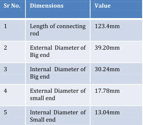
Table 1 Dimensions of connecting rod
Sr No. Dimensions Value
1 Length of connecting
rod 123.4mm
2 External Diameter of
Big end 39.20mm
3 Internal Diameter of
Big end 30.24mm
4 External Diameter of
small end 17.78mm
5 Internal Diameter of
Small end 13.04mm
The connecting rod of production engine is generally made up of production steel. In this analysis the first material for design is conventional material i.e. Carbon steel (AISI 1070 steel). In case of racing cars the connecting rod is made of aluminium and its composites alloy because it is light weight in comparison to steel and also it has higher ability to absorb high impact at the expense of durability or titanium because it is high strength material with light weight. But AISI 4337 steel also shows similar properties to carbon steel. So in this analysis second material for connecting rod is AISI 4337 steel. Carbon content in AISI 1070 steel is 0.65-0.75% and in AISI 4337 steel it is 0.35-0.45%. Due to this AISI 4337 steel is less brittle in comparison to AISI 1070 steel.
Pressure calculation
ρ petrol = 750.12 Kg/m3
ρ = 750.12 x 10 -9Kg/m3
Atmospheric Temperature, T = 298K
m = ρ x v
m = 750.12x10-9 x 97.2x1000
m = 72.911x10⁻³ Kg
M petrol =114.218x10⁻³ Kg/mole
R petrol= 8314.31/114.218x10-3
R= 72.793 x 10³ J/Kg.mol.
From Gas law equation
PV = mRT
= 72.911x10-3 x72.793x103 x298/ (97.2x10³)
= 16.271 MPa
Design Calculation
F1 = P x π/4 x D2
=16.271xπ/4x502
[image:3.595.311.556.430.555.2]= 31948.03 N
[image:3.595.310.557.586.710.2]Figure no. 1 Meshing of connecting rod
Figure no. 2 Maximum shear stress in AISI 1070 steel
© 2019, IRJET | Impact Factor value: 7.211 | ISO 9001:2008 Certified Journal
| Page 1090
Figure no.4 Minimum shear stress in AISI 1070 steel [image:4.595.312.554.251.374.2]Figure no.5 Minimum shear stress in AISI 4337 steel
Figure no.6 Factor of safety in AISI 1070 steel
Figure no.7 Factor of safety in AISI 4337 steel
[image:4.595.40.285.405.527.2]Figure no.8 Total deformation in AISI 1070 steel
Figure no.9 Total deformation in AISI 4337 steel
4. CONCLUSIONS
The design of connecting rod is analysed by ANSYS workbench 13.0. By comparing the results obtain by analyses with standard data following conclusions are obtained.
1. Maximum shear stress In AISI 1070 steel 71.4mpa and in AISI 4337 steel it is 71.8 mpa. Maximum allowable shear stress in AISI 1070 steel is 530 Mpa and in case of AISI 4337 steel it is 550 mpa.
2. Maximum principal stress in AISI 1070 steel is 148.99 mpa and in case of AISI 4337 steel it is 133.71 mpa. Allowable principal stress in AISI 1070 steel is 620 mpa and in case of AISI 4337 steel it is 650 mpa.
3. The minimum value of safety factor in AISI 1070 steel is 0.18768 and in case of AISI 4337 steel it is 0.3712.
4. The maximum value of total deformation in AISI 1070 steel is 0.027064 and in case of AISI 4337 steel it is 0.031107.
REFERENCES
[image:4.595.39.286.557.680.2]© 2019, IRJET | Impact Factor value: 7.211 | ISO 9001:2008 Certified Journal
| Page 1091
2. Thakare nikhil u., bhusale nitin d., “finite elementanalysis of connecting rod using ansys”, international journal of advances in science engineering and technology,vol. 3, pp. 82-86, , 2015.
3. N.p. Doshi, n.k. Ingole, “analysis of connecting rod using analytical and finite element method”, international journal of modern engineering research (ijmer) vol.3, issue.1,pp-65-68, 2013.
4. Mohamed abdusalam hussin, er. Prabhat kumar sinha, dr. Arvind saran darbari, “design and analysis of connecting rod using aluminium alloy 7068 t6, t6511”, international journal of mechanical engineering and technology (ijmet), volume 5, issue 10, october (2014), pp. 57-69.
5. B. Anusha, dr.c.vijayabhaskar reddy, “ comparision of materials for two-wheeler connecting rod using ansys”, International journal of engineering trends and technology (ijett) – volume issue 9- sep 2013.
6. Mr. H. B. Ramani, mr.neeraj kumar, mr. P. M. Kasundra w. Li, d. Li and j. Ni ,“analysis of connecting rod different loading condition using ansys software”, international journal of engineering research & technology (ijert) vol. 1 issue 9, november- 2012
7. Sarihan and song, “design evaluation and optimization of connecting rod parameters using fem”, international journal of engineering and management research, vol.-2, issue-6, december 2012.
8. Atish gawale, a. A.shaikh and vinay patil, “nonlinear static finite element analysis and optimization of connecting rod”, World journal of science and technology 2012, 2(4):01-04. Issn: 2231 – 2587.
9. S.B. Chikalthankar, sharad, “Analysis & Optimization of Connecting Rod”, Second International Confe-rence on Emerging Trends in Engineering and Technology,2009,IEEE, pp. 86-91.
10. Mahesh, harsh tripathi, “Design Evaluation and Optimization of Connecting Rod Parameters using FEM”, IJEMR, Volume 2, Issue 6, December 2012, pp. 21-25.