Abstract—The paper presents an analytical method to synthesize a seven-bar slider mechanism with variable topology for motion between two dead-center positions. Synthesis is carried out in two phases for motion generation between two dead-center positions. The tasks like path generation with prescribed timing and function generation are also dealt with. A dyadic complex number method is used. The complexity nature of synthesis of multi-degree freedom mechanisms made simpler through variable topology operating in two phases. The general attractions of the method are simplicity, ease of operation, easy to understand, codable for programming etc.
Index Terms— seven-bar slider, variable topology; dead- center positions, press working, complex numbers.
I. INTRODUCTION
A seven-bar slider has two degrees of freedom. Various methods are proposed to synthesize it. A seven-bar slider with variable topology operates in two phases. In each phase, a link adjacent to the permanently fixed link of seven-bar slider is fixed temporarily and the resulting portion of the mechanism acts like a six-bar slider with single degree of freedom [1]. Metal forming is one of the oldest production processes and yet, it is one the most commonly used manufacturing technologies even today. In order to achieve the desirable punch motion, today many mechanical presses use multiple links. The metal forming operations like shearing, bending and deep drawing require different variable motions of the punch, like shearing requires very short stroke of the ram and deep drawing requires a slow and long stroke of the punch
[2, 3].The variable stroke lengths could be achieved by adjusting the link lengths as in case of adjustable mechanisms [4]. Here in this paper this is achieved through variable topology for seven-bar slider mechanism.
To begin with an overview of the available literature on variable topology is presented to form the basis of the present work. Rose [5], Ting and Tsai [6] and Ting [7] made indirect reference of five-bar variable topology mechanisms. Rawat [8] established a synthesis technique for a five-bar variable
Manuscript received March 18, 2010.
U. M. Daivagna is working as Assistant Professor in Mechanical Engineering Department of S T J Institute of Technology, Ranebennur, and Karnataka State, India. Pin: 581 115, phone: 0837326643,
fax:08373266427,email:[email protected].
Dr.S. S. Balli is working as Professor in Mechanical Engineering Department of Basaveshwar Engineering College, Bagalkot, and Karnataka State, India. Pin: 587 102, phone: 08354234060,
fax:08354234204,email:[email protected].
topology mechanism operating in two phases. Joshi et al. [9] and Joshi [10] used the dyad synthesis of a five-bar variable topology mechanism for circuit breaker applications. Balli and Chand dealt with motion between extreme positions [11], defects and solution rectification [12] of a five-bar variable topology mechanism. In the recent developments of mechanical presses, W.Z.Guo [2] et al. dealt with the design of mechanical press consisting of seven-bar slider mechanism of two degrees of freedom. Cai-Fang Meng et al [13] proposed the optimal design and control of a novel press with an extra motor. H. Zhou, Kwun-Lon Ting [2] dealt with adjustable slider-crank linkages for multiple path generation, T.S.Mruthunjaya [14] dealt with graphical synthesis of seven-bar mechanism. Daivagna and Balli [15] dealt with synthesis of an off-set five-bar slider mechanism with variable topology.
Many works on seven-bar linkages with variable topology mainly target on revolute joint type. Though there are works which deal with the five-bar slider crank linkages, they are not commonly found in industrial because of their limitations and difficulty in synthesizing [16].
In the methods presented above for variable topology mechanisms of seven-bar , off-set five-bar slider , the arbitrarily prescribed or chosen values lead to an infinite number of solutions to a given problem which result in a large domain of solution space. The solution obtained may be infeasible and one has to reiterate the solution steps till he/she gets a practically feasible mechanism, which functions satisfactorily. The criterion of motion of mechanism between its dead-center positions may be used to reduce the solution space between dead centers.
Since presses play a vital role in industry, further improvements in its synthesis adds a valuable contribution. Therefore, the objective of the present problem undertaken is to develop a non-iterative analytical method of solution to determine the links of a seven-bar slider mechanism with variable topology for motion between two dead-center positions of the mechanism. The stroke obtained in Phase-I is shorter than Phase-II. One can use Phase-I of the mechanism for the press which requires a shorter stroke and Phase-II of the mechanism may be used for the press which requires a longer stroke. Thus, a single seven-bar slider mechanism after synthesizing through variable topology method operates explicitly in Phase-I and Phase-II giving away two presses of different strokes which may be used for shearing and deep drawing operations .
Synthesis of a Seven-Bar Slider Mechanism with
Variable Topology for Motion between Two
Dead-center Positions
II. SEVEN-BAR SLIDER MECHANISM WITH VARIABLE
TOPOLOGY
[image:2.595.314.521.137.349.2]Any mechanism with five or more links and with two or more degrees of freedom could be made to act as variable topology mechanism operating in two or more phases [10, 11]. The planar seven-bar slider mechanism is shown in Fig.1. The operations of the mechanism in Phase-I and Phase-II shown in Figs.2 and 3 respectively are discussed in the following paragraphs.
2.1 Phase-I
In Phase-I, the link OcC is temporarily fixed and the
resulting mechanism is a six-bar slider mechanism of single degree of freedom. It is a combination of five-bar slider and four-bar mechanism in series. OaA1 is the input link. B is the
possible path tracer point. Suffix 1 and 2 of alphabets in Fig. 2 represent the two finitely separated positions of the six-bar slider portion of the seven-bar slider variable topology mechanism in Phase-I. C is a temporarily fixed pivot. Oa and
Oc are the permanently fixed pivots.
[image:2.595.61.242.290.495.2]Fig. 1. A planar seven-bar slider mechanism
Fig. 2. A planar seven-bar slider mechanism with variable topology at its two dead-center positions, in Phase-I
2.2. Phase-II
Once the above six-bar slider portion of seven-bar slider mechanism with variable topology reaches the position 2 , the link OcC is released to move and the link OaA is fixed
temporarily, thus switching on to the Phase-II. Again the resulting mechanism is six-bar slider of single degree of
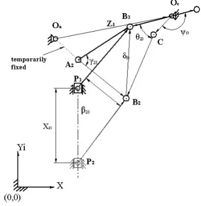
Fig. 2. A planar seven-bar slider mechanism with variable topology at its two dead-center positions, in Phase-II freedom. Here link OcC is input link, B is the tracer point.
Suffix 2 and 3 of alphabets in Fig.3 represent the two finitely separated positions of the six-bar slider portion of the seven-bar slider variable topology mechanism in Phase-II. Also, it is to be noted that C is no more a fixed pivot where as A2 is a temporarily fixed pivot. Oc and Oa are the permanently
fixed pivots.
III. SYNTHESIS
3.1 Solution steps
The solution to the problem consists of the following steps: (i) Identification of the links to be fixed temporarily in each phase so that in both the phases one can get six-bar slider portion of seven-bar slider variable topology mechanism.
(ii) Recognization of the type of mechanism in each phase.
(iii) Writing of the standard dyad equations for the motion between position 1 and position 2 of Phase-I and also between position 2 and position 3 of Phase-II.
(iv) Identification of the values to be prescribed, values to be chosen freely and the unknowns based on the task to be performed.
(v) Solving of the equations of motion in each phase for the link lengths.
(vi) Retaining of link parameters determined in Phase-I while solving other link lengths in Phase-II. (vii) Finding of the total number of solutions that are
possible in all phases by the method.
When it is required to synthesize a planar seven-bar slider mechanism (shown in Fig.1) with variable topology, one can have three options as follows:
[image:2.595.56.280.423.718.2](ii) Other end link is fixed temporarily, (iii) Middle link, the slider is fixed temporarily. The options (i) and (ii) are considered for the present paper. It is assumed that the mechanism moves from dead center position 1 to the dead center position 2 in Phase-I and from the dead center position 2 to the dead center position 3 in Phase-II. In the present case, as soon as the mechanism moves from one dead-center position to the other, it stops and
then switches on to the Phase-II. So there is no question of overcoming the dead lock and hence, no auxiliary drive is needed. Moreover, the dead lock positions can overcome by inertia forces of the cranks.
Table I
Conventions to be followed to denote the linkages and the angles in Phase-I and in Phase-II Link Phase-I Phase-II Vectors and angles Position 1 to 2 Position 2 to 3 OaA1 =Z2 , φ φ12 Temporarily fixed
A1B1= Z3,γ γ12 γ23
B1P1 =Z4,β β12 β23
C1B1 = Z5 , θ θ12 θ23
Oc C = Z6 , ψ Temporarily fixed ψ23
Oa C =Z1 From Oa to C ---
Oa P = Z7 From Oa to P1 ---
12
X , X23 Slider displacement slider displacement
2
1
= Z7V+X12/Z7V 12 is Stretch ratio ---
7H
Z =e Eccentricity between Oa and slider path ---
OaOc = Z8 From Oa to Oc ---
8V
Z = d1 Vertical offset for OaOc ---
8H
Z =d2 Horizontal offset for OaOc ---
Displacement vector B1B2 = δ12 B2B3 = δ23
Number of solutions ∞ 6 ∞1
Total number of solutions ∞ 7
Sign convention CCW motion is +ve CW motion is –ve , Linear displacement upward is +ve Downward is -ve The conventions to be followed in Phase-I and Phase-II
are given in Table 1. The input motion in Phase-I is φ12 ,
the displacement vector B1B2 is given by δ12 .
Writing the dyad equations [1, 17] for Phase-I (refer Fig.2),
2
Z (ei12 1) +
3
Z (eiγ12 1) = 12
(1)
7H
Z (ρ121) + Z4(eiβ12 1) = 12
(2)
12
X + Z4(eiβ12 1) = 12
(3)
5
Z (eiθ12 1) = 12
(4) 3.2 Motion generation
In motion generation mechanisms, the body to be guided usually is a part a floating link. Hence, the location of tracer point on the coupler and the coupler orientation are the part of design specifications as the entire motion of the coupler link is to take place. It requires that an entire body be guided through a prescribed motion order. 3.2.1 Phase-I synthesis
In the standard dyad Eqs.(1)-(4), in motion generation, the coupler point motions (γ12, β12) and the displacement
vector δ12 are prescribed. φ12 , X12, θ12 and Z2are the free choices. Hence, there will be ∞ 6 numbers of solutions.
Then the unknowns Z3 , Z4 , Z5 , Z7 and Z1 are determined as follows;
3
Z =
) 1 (
) 1 ( 12
12
iγ
i 12
e e Z2
(5)
4 Z =
) 1 ( δ
12 iβ
12
e
12
X
(6)
5
Z =
) 1 ( iθ12
12
e
(7) From loop closure equation,
7
Z = Z2+ Z3-Z4 (8)
1
Z = Z2+ Z3-Z5 (9) Also, Z7=Z7V+ Z7H (10)
Off-set = e = Z7H= - Z7Sin α1 ei(90-α1) (11) Where α1 is the angle made by Z7with the vertical line
passing through Oa in CW.
3.2.2 Phase-II synthesis
Input motion in Phase-II is ψ23 the displacement vector
B1B2 is given by δ23 .
Writing the dyad equations for Phase-II (refer Fig. 3)
6
Z (eiψ231) +
5
Z eiθ12(ei23 1) = δ
23 (12)
3
Z ei12 (eiγ23 1) = δ
23 (13)
23
X + Z4ei12(ei231) = δ
Here δ23 and θ23 are prescribed, γ23 is a free choice.
Therefore, there will be ∞1 number of solutions. Hence the
total number of solutions from Phase-I and Phase-II are
∞7. The link lengths determined in Phase-I are retained in
Phase-II Then, the unknownsZ6, Z8, vertical off-set d1
and horizontal off-set d2 (refer Fig.3) are determined as
follows; 6 Z = ) 1 ( ) 1 ( 23 23 12 i iθ iθ 23 e e e 5 Z (15) From loop closure equation,
8
Z = Z2 ei12+
3
Z ei12
5
Z eiθ12-
6
Z (16) Now, α2 is the angle made by Z8with the horizontal line
passing through Oc in CW (refer Fig.3)
Vertical off-set = d1 = Z8V = Z8Sin α2 eiα2 (17)
Horizontal off-set = d2 =Z8H = Z8Cos α2 e-i(90α21) (18) 3.3 Path generation with prescribed timing
In path generation a point on a floating link is to trace a path defined with respect to the fixed frame. If the path points are to be correlated with either time or input link positions, the task is called as path generation with prescribed timings. For this purpose, location of a tracer point on the coupler and the position of the input link are the part of the design specifications. The position of the link must correspond to each position of the tracer point on the coupler. The path of tracer point i.e. motion of coupler point and rotation of one crank are to be prescribed. The values to be prescribed and to be chosen freely in case of motion generation problem are to be interchanged for the path generation with prescribed timing [1, 17].
3.3.1 Phase-I synthesis
The input crank motion φ12, linear displacement
vectorX12, θ12 and δ12 are prescribed. γ12 ,β12 andZ2are
the free choices. Hence, there will be ∞ 4 number of
solutions .Then the unknownsZ3,Z4,Z5,Z7,Z1and e are determined using the Eqs. 5-11 respectively.
3.3.2 Phase-II synthesis
Prescribed parameters are δ23 and ψ23 and θ23 is a free
choice. Therefore, there willbe ∞number of solutions.
6
Z ,Z8, d1 and d2 are determined using Eqs. 15-18
respectively.
3.4 Function generation
In function generation mechanism, relative motion or forces between links connected to ground is taken into account. It is required to coordinate the rotation or sliding motion of input and output links for two specified design positions [1, 17, and 18].
3.4.1 Phase-I synthesis
In function generation problem, the output and input motion are φ12,X12 , θ12 and Z5are prescribed. γ12 , β12
and Z2 are free choices.Therefore, there will be ∞4
numberofsolutions.Then unknownsZ3,Z4,Z7,Z1and e
are determined as follows; 2
Z (ei12 1) +
3
Z (eiγ12 1) =
5
Z (eiθ12 1) (19)
12
X + Z4(eiβ12 1) =
5
Z (eiθ12 1) (20) Let Z5(eiθ121) = 12 (21) Where 12is the displacement of the vector B1B2.
Reducing the Eqs.19 and 20 to the forms of standard
dyadic equations [1, 11, 17, and 18] as follows; 2
Z (ei12 1) +
3
Z (eiγ121) = 12
(22)
12
X + Z4(eiβ12 1) = 12
(23)
3 Z = ) 1 ( ) 1 ( 12 12 iγ i 12 e e
Z2
(24) 4 Z = ) 1 ( δ 12 iβ 12 e 12 X (25) 7
Z ,Z1and e are determined using Eqs. 8-11respectively.
3.4.2 Phase-II synthesis
Writing the loop closure equation for the Phase-II (refer Fig.3),
6
Z (eiψ231) +
5
Z eiθ12(ei23 1) =
3
Z ei12 (eiγ231)
(26)
23
X + Z4ei12(ei231) =
3
Z ei12 (eiγ231) (27) Let Z3 ei12 (eiγ231) = δ
23 (28)
Reducing the Eqs. 26 and 27 to the forms of standard dyadic equations [1, 17] as follows;
Z6(eiψ23 1) +
5
Z eiθ12(ei231) = δ
23 (29)
X23 + Z4 ei12(ei23 1) = δ
23 (30)
Here ψ23, X23 and β23 are prescribed and θ23 is the free
choice. Therefore, there will be ∞ number of solutions.
6
Z ,Z8, d1 and d2 are determined as follows;
When δ23 (or γ23 )and ψ23 are prescribed.
) 1 ( ) 1 ( -) 1 ( 23 23 12 23 12 i i i i i e e e e e 5 4 23 6 Z Z X
Z (31)
8
Z , d1 and d2 are determined using Eqs. 16-18
respectively.
IV. SOLUTION SPACE
The method gives an infinite number of solutions depending upon the number of free choices made. In order to obtain practically useful mechanisms, it is necessary to reduce the solution space by calculating the free choices in terms of known parameters. [1, 17].
V. ADVANTAGES OF THE METHOD
The dyad technique by Sander and Erdman permits handling any type of bar-slider mechanism and is extensively used for the synthesis of single degree of freedom mechanisms. Here it has been applied to variable topology mechanisms, which in this case are two degrees of freedom systems. The method reduces the job of synthesizing seven-bar slider mechanism of two degrees of freedom to design a six-bar slider mechanism with one degree of freedom in two phases. The synthesis of a six-bar slider mechanism is simpler. Thus the method is simpler compared with other methods of synthesis of seven-bar slider mechanism. Following are the some of the advantages of the method.
Simplicity, ease of application and generality.
Increased accuracy over graphical methods. VI. LIMITATIONS OF THE METHOD
The synthesized mechanism by the method may suffer from defects like circuit and branch which can be rectified separately.
The solution does not permit good initial free choices for all possible solutions.
VII. APPLICATION OF THE METHOD
The synthesized seven-bar slider mechanism with variable topology can be applied to mechanical press operations. The steps involving in these operations are as follows;
Let the input motor for the mechanism be link 2 in Phase-I and link 6 in Phase-II.
For the shearing operation (Phase-I), let the input parameter link 6 be temporarily fixed or locked.
The punch and die for the operation may be suitably arranged to perform the shearing.
Switch on the motor, one can operate the shearing operation.
After the completion of the shearing, release the link 6 and temporarily fix or lock link 2.
The punch and die for the drawing operation may be suitably arranged.
Switch on the second motor of link 6 and one can carryout the drawing operation.
Thus the same press can be used for multiple operations, thus it is economical.
VIII. CONCLUSION
The proposed method is for the synthesis of seven-bar slider mechanism with variable topology for the motion generation between two dead-center positions. In the present work, order is not significant as the numbers of design positions are two. The synthesized mechanism is free from Grashof’s because of rotary inputs of the mechanism in both the phases. There may be circuit and branch defects [12]. The proposed method reduces the synthesis of seven-bar slider mechanism of two degrees of freedom to the synthesis of a six-bar slider mechanism but in two phases of operations. The application and the advantages of the method to shearing in Phase-I and drawing in Phase-II is discussed. The method proposed is simple, easy to understand. The authors are more concerned with developing the variable topology mechanisms for the industrial purpose to save cost and energy. The solution rectification of the proposed mechanism is to be undertaken in the future work.
EXAMPLE
It is required to synthesize a seven-bar slider mechanism with variable topology for the motion between two dead-center positions, used for press working operations in two phases. Following are the tracer point displacement specifications;
Phase-I: from point (107.0600, 149.0600) to the point (142.2800, 103.0600)
Prescribed parameters are γ12 = -27.940 and β12 = -31.580
Phase-II: from point (142.2800, 103.0600) to the point (154.3900, 139.6400)
Prescribed parameters are δ23 = (12.11 +36.58i),
θ23 = -5.660 CW
Solution: (a) Motion generation
Phase-I: Given that: displacement =δ12 = (35.22 -46.0i), γ12
= -27.940 and β
12 = -31.580 (Prescribed parameters)
Let Z2= (-26.14 + 4.92i), X12= (0-33.03i), θ12 = +58.220
and φ12 = +144.530 (Free choices)
From Eq.5,
3
Z = (52.0775-9.7811i) =52.9775
169.36060From Eq.6, 4
Z = (5.3228+68.7590i) = 68.9647
85.57340FromEq.7,
5
Z = (-58.9157–8.6260i) =59.5439
188.32960FromEq.5,
7
Z = (20.6039–73.6300i) =76.4585
288.63320From Eq.9,
1
Z = (84.7824 + 3.7649i) = 84.8660
2.54270From Eq.11,
Off-set = e = (20.6038 +0i) =20.6038
00Phase-II: Given that: displacement,δ23=(12.11+ 36.5800i)
and θ23 = -5.660 CW
Let ψ23 = +174.340 CCW (free choice)
From Eq.15,
6
Z = (-9.5310-16.5586i) =19.1057
240.07550From Eq.16,
8
Z = (96.5371+20.3235i) =96.5371
12.15310From Eq.17,
8V
Z =Vertical offset, d1 = (0+20.3300i) =20.3300
900From Eq.18,
8H
Z =Horizontal off-set, d2 = (94.3735+0i) =97.3735
00(b) Path generation with prescribed timing
Phase-I: Given that: displacement =δ12 = (35.22 -46.0i),
φ12 = +144.530,X12= (0-33.03i) and θ12 = +58.220
Let Z2= (-26.14 + 4.92i), γ12 = -27.940 and β12 = -31.580
(Free choices) From Eq.5,
3
Z = (52.0775-9.7811i) =52.9775
169.36060From Eq.6, 4
Z = (5.3228+68.7590i) = 68.9647
85.57340FromEq.7,
5
Z = (-58.9157-8.6260i) =59.5439
188.32960FromEq.5,
7
Z = (20.6039–73.6300i) =76.4585
288.63320From Eq.9,
1
Z = (84.7824 + 3.7649i) = 84.8660
2.54270From Eq.11,
Off-set = e =Z7H=(20.6038 +0i) = 20.6038
00Phase-II: Given that:
Displacement, δ23= (12.11 + 36.5800i) and ψ23 = +174.340
Let θ23 = -5.660 CW (free choice)
FromEq.15,
6
Z = (-9.5310-16.5586i) =19.1057
240.07550From Eq.16,
8
Z = (96.5371 + 20.3235i) = 96.5371
12.15310From Eq.17,
8V
Z =d1 =Vertical offset Off-set
= (0+20.3300i) =20.3300
9008H
Z =d2 =Horizontal off-set = (94.3735+0i) =97.3735
00(b) Function generation
Phase-I: Given that: φ12 = +144.530 ,X12= (0-33.03i) and
θ12 = +58.220 and Z5= (-58.9157 – 8.6260i)
From Eq. 21, displacement =δ12 = (35.22 -46.0i),
Let Z2= (-26.14 + 4.92i), γ12 = -27.940 and β12 = -31.580
(Free choices) From Eq.24,
3
Z = (52.0775-9.7811i) = 52.9775
169.36060From Eq.25, 4
Z = (5.3168 + 68.7562i) = 68.9615
85.57820From Eq.5,
7
Z = (20.6099 – 73.6273i) = 76.4575
285.63810From Eq.9,
1
Z = (84.7824 + 3.7649i) = 84.8660
2.54270From Eq.11,
Off-set = e = Z7H= (20.6100 +0i) = 20.6100
00Phase-II:
Given that: ψ23=+174.340CCW,X23=(0+47.6300i),
β23 = -13.76000, Z3= (52.0775-9.7811i) and
γ23 = 42.780 CCW .θ23 = -5.660 CW (free choice)
From Eq.28, δ23 = (11.4207 + 36.9174i)
From Eq.31,
6
Z = (-9.1954 – 16.7443i) = 19.1031
241.22590From Eq.16,
8
Z = (94.0378 + 20.4992i) = 96.2462
12.29750From Eq.17,
8V
Z =d1=Vertical offset= (0 + 20.3300i) = 20.5004
900From Eq.18,
8H
Z =d2=Horizontal off-set=(94.0378+0i)= 94.0378
00REFERENCES
[1] Shrinivas Balli and Satish Chand. Synthesis of a planar seven-link mechanism with variable topology for motion between two dead-center positions, Mechanism & Machine Theory, 38(11),2003,1271-1287pp.
[2] R.Du and W.Z.Guo, The design of a new metal forming press with controllable mechanism, Transactions of the ASME, Vol.125, September 2003, 582-592.
[3] P C Sharma, Production Engineering, Eighth Revised Edition, S Chand and Company Ltd, New Delhi, 1997.
[4] H Zhou ,Kwun-Lon Ting , Adjustable slider-crank linkages for multiple path generation, Mechanism & Machine Theory, 37(5),2002,499-509pp.
[5] Stanley E Rose. Five-bar loop synthesis. Machine Design, October 12th, 1961, pp 189-195.
[6] K L Ting H Tsai, Mobility and synthesis of five-bar programmable linkages, in: Proceedings of 9th OSU
Applied Mechanism Conference, Kansas City, MD, 1985, pp III-1-III-8.
[7] K L Ting, Five-bar Grashof’s criteria, Transaction the ASME,Journal of Mechanisms,Transmissions and Automation in Design (December),1986,pp533-537. [8] Yogesh Rawat, Synthesis of Variable Topology
Mechanisms Graphical Method, Dissertation, M.E.D.IIT, Bombay, 1997.
[9] S.A.Joshi, C.Amaranath, Synthesis of Variable Topology Mechanisms for Circuit Breaker Applications, in: Proceedings of the 8th NaCOMM Conference, I.I.T Kanpur, 1997.
[10] S A Joshi, Variable topology mechanisms for circuit breaker applications, MTech,Dissertation, Mechanical Engineering Department, IIT,Bombay,1998.
[11] Shrinivas Balli and Satish Chand, Synthesis of Five-bar Mechanism with Variable Topology for Motion between Extreme positions, Mechanisms and Machine Theory, 36(10), 2001, pp 1147-1156. [12] Shrinivas. Balli and Satish. Chand, Defects in link
mechanisms and solution rectification, Mechanisms and Machine Theory, 37(10), 2002, pp 857-876. [13] Cai-Fang Meng, Ce-Zhang, Yong-Hui, Zhao-Guang
Shen, Optimal design and control of a novel press with an extra motor , Mechanisms and Machine Theory, 39(8), 2004, pp 811-818.
[14] Mruthunjaya T S, Synthesis of plane linkages to generate function of two variables using point position reduction –II.Sliding inputs and output, Mechanisms and Machine Theory, 7(4) , 1972, pp 399-405.
[15] Daivagna.U.M and S.S.Balli, FSP Synthesis of an off-set Five Bar-Slider Mechanism with Variable Topology,Proc of NaCoMM2007, Indian Institute of Science, Bangalore, pp 345-350.
[16] H Zou and Kwun-Lon Ting, Path Generation with Singularity avoidance for Five-bar slider crank parallel Manipulators, Mechanisms and Machine Theory, 40(3), 2005, pp 371-384.
[17] A G Erdman and G N Sandor, Mechanism Design: Analysis and Synthesis, Vol-lI, 1999, PH, New Delhi, 1997.