EMC Corporation Corporate Headquarters: Hopkinton, MA 01748-9103 1
-508-435-1000
www.EMC.comfor VMware ESX Server
P/N 300-002-304 REV 44
EMC believes the information in this publication is accurate as of its publication date. The information is subject to change without notice.
THE INFORMATION IN THIS PUBLICATION IS PROVIDED “AS IS.” EMC CORPORATION MAKES NO REPRESENTATIONS OR WARRANTIES OF ANY KIND WITH RESPECT TO THE INFORMATION IN THIS PUBLICATION, AND SPECIFICALLY DISCLAIMS IMPLIED WARRANTIES OF MERCHANTABILITY OR FITNESS FOR A PARTICULAR PURPOSE.
Use, copying, and distribution of any EMC software described in this publication requires an applicable software license.
EMC2, EMC, and the EMC logo are registered trademarks or trademarks of EMC Corporation in the United
State and other countries. All other trademarks used herein are the property of their respective owners. For the most up-to-date regulator document for your product line, go to EMC Online Support
Preface... 11
Chapter 1 Introduction to VMware Infrastructure/ vSphere VMware vSphere... 18
vSphere 4... 18
vSphere 5... 18
VMware ESX/ESXi Server... 19
VMkernel ... 19
Service console ... 20
Useful VMware ESX/ESXi Server utilities and functions ... 21
Control interface... 23
VMware Web UI ... 23
VMware vSphere Client ... 23
VMware vCenter Server ... 23
Connecting EMC storage with ESX/ESXi Server... 24
Chapter 2 Installation of ESX/ESXi Server Installation ... 26
Installation media ... 26
Installation methods... 26
Initiator setting and installation ... 28
Host Bus Adapter (HBA)... 28
iSCSI card ... 29
Converged Network Adapter (CNA) ... 30
Adapter installation... 31
Install adapter card... 31
Chapter 3 Connectivity
Fibre Channel ... 34
Fabric zoning... 34
Symmetrix connectivity... 34
VNX series and CLARiiON connectivity... 40
iSCSI... 50
VMware ESX SW iSCSI... 51
VMware ESX HW iSCSI ... 63
Symmetrix connectivity... 64
VNX series and CLARiiON connectivity... 67
FCoE initiator configurations... 71
Configuring Emulex FCoE CNAs with VMware ESX Server... 71
Configuring QLogic FCoE CNAs with VMware ESX Server... 80
Configuring Brocade FCoE CNAs with VMware ESX Server... 85
Cisco Unified Computing System with FCoE... 90
Configuring FCoE for Intel Ethernet Server Adapter with VMware ESX server ... 92
Chapter 4 Array Information and Configuration Symmetrix array configurations... 94
Required storage system configuration ... 94
Addressing Symmetrix devices... 94
EMC Symmetrix Management Console (SMC) ... 98
Recommendations for optimal performance... 103
ESX host in the VNX series and CLARiiON environment ... 105
VNX series and CLARiiON failover modes ... 105
Adding the VMware ESX server host to a storage group ... 108
Performing a VNX series and CLARiiON NDU with VMware ESX server hosts ... 109
Manual trespass on VNX series and CLARiiON systems to recover the original path ... 116
EMC VPLEX ... 123
Overview ... 123
Prerequisites ... 129
Provisioning and exporting storage ... 130
Storage volumes... 132
System volumes ... 134
Required Symmetrix FA bit settings ... 135
Supported storage arrays... 137
Initiator settings on back-end arrays... 137
Host connectivity ... 137
Exporting virtual volumes to hosts ... 138
Front-end paths ... 142
Configuring VMware ESX hosts to recognize VPLEX volumes ... 144
EMC XtremIO ... 145
Best practices for zoning and subnetting... 145
Configuring a VMware vSphere host ... 148
Configuring Fibre Channel HBA... 155
Configuring multipath software... 160
File system and application requirements ... 166
Chapter 5 Multipathing in VMware ESX/ESXi Server Overview ... 172
Path policies ... 172
Multipathing in VMware ESX Server with Symmetrix ... 174
Multipathing in VMware ESX 3.x with CLARiiON ... 175
Native multipathing in VMware ESX/ESXi 4.x and ESXi 5.x .. 176
Symmetrix policy ... 176
VNX series and CLARiiON policy ... 176
Multipathing in VMware ESXi/ESX 5.x and ESXi 4.x with VPLEX... 177
ESX Server 4.x... 179
ESX/ESXi 4.x and ESXi 5.x ... 179
PowerPath /VE for VMware ESX/ESXi 4.x and ESXi 5.x... 181
Major components ... 182
Supported storage types ... 182
PowerPath commands... 183
Claim rules ... 184
Appendix A Migration Considerations ESX 3.0.x ... 186
ESX 3.5 ... 187
Appendix B Virtual Provisioning
Virtual Provisioning ... 190
Terminology ... 190
Traditional versus Virtual (thin) Provisioning ... 192
Monitoring, adding, and deleting pool capacity ... 193
Virtual LUN architecture and features ... 195
VMware Virtual Machine File System with thin LUN ... 197
ESX 3.x... 197
ESX 4.x... 198
Virtual Provisioning with VNX series and CLARiiON ... 199
Virtual Provisioning on VMware ESX v3.x ... 199
Virtual Provisioning on VMware ESX v4.x ... 202
Virtual Provisioning with Symmetrix ... 212
Main components ... 212
Management tools ... 213
Virtual Provisioning on EMC Symmetrix VMAX ... 214
Implementation considerations ... 224
Appendix C Virtual Machine File System VMFS datastore ... 226
Volume alignment ... 227
Version history ... 228
Size limits ... 229
Appendix D Raw Disk Usage and Mapping Raw disk usage and caveats ... 232
Raw Device Mappings (RDM) ... 233
Appendix E Boot from SAN Booting from Symmetrix storage arrays ... 236
Title Page
1 One host, two switches, and one Symmetrix array ... 36
2 One host, two switches, and four Symmetrix arrays ... 37
3 SMC Properties verification screen ... 38
4 Solution Enabler CLI verification screen ... 39
5 One host, two switches, and one VNX series or CLARiiON systems .... 42
6 One host, two switches, and four VNX series or CLARiiON systems ... 43
7 Connectivity Status dialog ... 45
8 Registering for a failover-enabled environment example ... 47
9 Warning message example ... 48
10 Host reported as attached, but manually registered example ... 49
11 SCSI commands encapsulated by Ethernet headers ... 50
12 VMkernel and service console on a single vSwitch ... 51
13 Two NICs on a single vSwitch iSCSI configuration ... 57
14 Two NICs in dual vSwitch iSCSI configuration ... 58
15 vSwitch configuration ... 59
16 Cisco Unified Computing System example ... 91
17 SMC interface example ... 99
18 Device Masking and Mapping-Masking dialog box ... 100
19 Masking: Set LUN Addresses dialog box ... 101
20 Set Port Attributes dialog box ... 102
21 Register Initiator Record window ... 108
22 Storage Group Properties window ... 109
23 Software Installation Wizard ... 111
24 Software Installation Wizard window ... 112
25 Non-Disruptive Upgrade Delay window ... 113
26 Software Package Selection window ... 115
27 Software Operation Progress History window ... 116
28 LUNs example ... 118
29 View LUN properties ... 119
31 Confirm trespass LUNs ... 121
32 Report on LUNs ... 122
33 VPLEX provisioning and exporting storage process ... 131
34 Create storage view ... 139
35 Register initiators ... 140
36 Add ports to storage view ... 141
37 Add virtual volumes to storage view ... 142
38 VMkernel pluggable storage architecture ... 180
39 Traditional storage provisioning ... 192
40 Virtual (thin) provisioning ... 192
41 Pool % Full Threshold ... 193
42 Reserved capacity ... 194
43 LUN threshold and allocation limit ... 195
44 Reserved capacity ... 196
Title Page
1 EMC models and minimum operating system requirements ...12
2 Useful utilities and functions for VMware ESX Server 3.x ...21
3 Useful utilities and functions for VMware ESX Server 4.x ...21
4 Useful utilities and functions for VMware ESXi 5 ...22
5 Symmetrix SCSI-3 addressing modes ...96
6 Symmetrix director bit setting for ESX Server environments ...98
7 Required Symmetrix FA bit settings for connection to VPLEX ...136
8 Supported hosts and initiator types ...144
As part of an effort to improve and enhance the performance and capabilities of its product line, EMC from time to time releases revisions of its hardware and software. Therefore, some functions described in this document may not be supported by all revisions of the software or hardware currently in use. For the most up-to-date information on product features, refer to your product release notes.
If a product does not function properly or does not function as described in this document, please contact your EMC representative.
This guide describes the features and setup procedures for VMware ESX Server host interfaces to EMC Symmetrix, VMAX, VNX, and CLARiiON storage systems. This document is meant to assist in the installation and configuration of VMware ESX Server attached to Symmetrix, VMAX, VNX, and CLARiiON systems.
Audience This guide is intended for use by storage administrators, system
programmers, or operators who are involved in acquiring, managing, or operating Symmetrix, VMAX, VNX, and CLARiiON, and host devices.
Readers of this guide are expected to be familiar with the following topics:
◆ Symmetrix, VMAX, VNX, and CLARiiON system operation
VMAX, Symmetrix, VNX, and CLARiiON references
Unless otherwise noted:
◆ Any general references to Symmetrix or Symmetrix array include the VMAX3 Family, VMAX, and DMX.
◆ Any general references to VNX include VNX5100/5200/5300/ 5400/5500/5600/5700/5800/7500/7600/8000.
◆ Any general references to CLARiiON or CLARiiON array include the FC4700, FC4700-2, CX, CX3, and CX4.
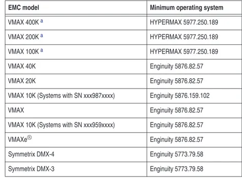
Table 1lists the minimum EMC Enginuity™and EMC HYPERMAX requirements for EMC VMAX and Symmetrix models.
a. VMAX 400K, VMAX 200K, and VMAX 100K are also referred to as the VMAX3™Family. Related
documentation
For the most up-to-date information for supported server and HBA combinations, always consult theEMC Support Matrix(ESM), available through E-Lab Interoperability Navigator (ELN) at
http://elabnavigator.EMC.com.
For VMware-specific documentation, such as theVMware ESX Server Release Notes,ESX Server Administration Guide,and theESX Server Installation Guide, go to:
http://www.VMware.com/support
Table 1 EMC models and minimum operating system requirements
EMC model Minimum operating system
VMAX 400Ka HYPERMAX 5977.250.189
VMAX 200Ka HYPERMAX 5977.250.189
VMAX 100Ka HYPERMAX 5977.250.189
VMAX 40K Enginuity 5876.82.57
VMAX 20K Enginuity 5876.82.57
VMAX 10K (Systems with SN xxx987xxxx) Enginuity 5876.159.102
VMAX Enginuity 5876.82.57
VMAX 10K (Systems with SN xxx959xxxx) Enginuity 5876.82.57
VMAXe® Enginuity 5876.82.57
Symmetrix DMX-4 Enginuity 5773.79.58
For a list of supported guest operating systems, refer to the VMware
Guest Operating System Installation Guide, located at:
http://www.VMware.com/pdf/GuestOS_guide.pdf Conventions used in
this guide
EMC uses the following conventions for notes and cautions.
Note:A note presents information that is important, but not hazard-related.
IMPORTANT
An important notice contains information essential to operation of the software.
Typographical conventions
EMC uses the following type style conventions in this guide:
Bold Used for names of interface elements, such as names of windows, dialog boxes, buttons, fields, tab names, key names, and menu paths, (what the user specifically selects or clicks)
Italic Used for full titles of publications referenced in text
Courier Used for:
• System output, such as an error message or script • System code
• Pathnames, filesnames, prompts, and syntax • Commands and options
Courier bold Used for user input.
Courier italic Used for variables.
< > Angle brackets enclose parameter or variable values supplied by the user
[ ] Square brackets enclose optional values
| Vertical bar indicates alternate selections - the bar means “or”
{ } Braces indicate content that you must specify (that is, x or y or z)
Where to get help EMC support, product, and licensing information can be obtained as follows.
EMC support, product, and licensing information can be obtained on the EMC Online Support site as described next.
Note:To open a service request through the EMC Online Support site, you must have a valid support agreement. Contact your EMC sales representative for details about obtaining a valid support agreement or to answer any questions about your account.
Product information
For documentation, release notes, software updates, or for
information about EMC products, licensing, and service, go to the EMC Online Support site (registration required) at:
https://support.EMC.com Technical support
EMC offers a variety of support options.
Support by Product —EMC offers consolidated, product-specific information on the Web at:
https://support.EMC.com/products
The Support by Product web pages offer quick links to
Documentation, White Papers, Advisories (such as frequently used Knowledgebase articles), and Downloads, as well as more dynamic content, such as presentations, discussion, relevant Customer Support Forum entries, and a link to EMC Live Chat.
EMC Live Chat —Open a Chat or instant message session with an EMC Support Engineer.
eLicensing support
To activate your entitlements and obtain your Symmetrix license files, visit the Service Center onhttps://support.EMC.com, as directed on your License Authorization Code (LAC) letter e-mailed to you. For help with missing or incorrect entitlements after activation (that is, expected functionality remains unavailable because it is not licensed), contact your EMC Account Representative or Authorized Reseller.
For help with any errors applying license files through Solutions Enabler, contact the EMC Customer Support Center.
If you are missing a LAC letter, or require further instructions on activating your licenses through the Online Support site, contact EMC's worldwide Licensing team [email protected] call:
◆ North America, Latin America, APJK, Australia, New Zealand: SVC4EMC (800-782-4362) and follow the voice prompts.
◆ EMEA: +353 (0) 21 4879862 and follow the voice prompts.
We'd like to hear from you!
Your suggestions will help us continue to improve the accuracy, organization, and overall quality of the user publications. Send your opinions of this document to:
This chapter provides information about the VMware infrastructure vSphere, including:
◆ VMware vSphere... 18
◆ VMware ESX/ESXi Server... 19
◆ Control interface... 23
◆ Connecting EMC storage with ESX/ESXi Server... 24
Note:In this document, Virtual Infrastructure (VI) and vSphere are used interchangeably.
Introduction to
VMware Infrastructure/
vSphere
VMware vSphere
VMware has renamed its infrastructure product to vSphere. The following versions are briefly discussed in this section:
◆ “vSphere 4” on page 18 ◆ “vSphere 5” on page 18
vSphere 4
VMware vSphere 4 is the industry’s first cloud operating system, transforming IT infrastructures into a private cloud, a collection of internal clouds federated on-demand to external clouds, delivering IT infrastructure as a service.
vSphere 4 supports 64-bit VMkernel and service console. The service console version is derived from a release of a leading enterprise Linux vendor.
vSphere 5
VMware vSphere 5 supports virtual machines (VMs) that are up to four times more powerful than previous versions with up to 1 terabyte of memory and 32 virtual CPUs. These VMs are able to process in excess of 1 million I/O operations per second. When combined with VMware vSphere 5's enhanced, simplified High Availability, performance, and availability is greatly improved. VMware vSphere 5 also supports the automated approach to manage data center resources, including server deployment and storage management. Customers define policies and establish the operating parameters, and VMware vSphere 5 does the rest. The three key features to enable the automated processes are:
◆ Auto-Deploy
◆ Profile-Driven Storage
VMware ESX/ESXi Server
VMware ESX Server is the main building block of the VMware infrastructure. It provides a platform for multiple virtual machines sharing the same hardware resources, (including processor, memory, storage, and networking resources), the ability to perform all the functions of a physical machine. This maximizes the hardware utilizing efficiency while minimizing installation capital and operating cost.
VMware ESX Server consists of two main components, discussed briefly in this section:
◆ “VMkernel” on page 19 ◆ “Service console” on page 20
◆ “Useful VMware ESX/ESXi Server utilities and functions” on page 21
The interaction between them forms a dynamic and reliable virtualized environment, providing virtual machines with high availability, resource management, operational automation and security features that improve service quality levels even to the most resource-intensive mission-critical applications.
VMkernel
The ESX Server virtualized layer, VMkernel, runs on bare metal, handling CPU and memory directly without going through a third-party operating system. VMkernel uses Scan-Before-Execution (SBE) to handle special or privileged CPU instructions.
To access other hardware, including network and storage devices, vmkernel modules are used. Some of the modules are derived from the Linux kernel modules.
VMkernel can provide services including CPU scheduling, memory management and virtual switch data processing for virtual machines to access the underlying physical hardware of the server, where they are built on.
VMkernel manages all the operating systems on the machine, including both the service console and the guest operating systems running on each virtual machine.
VMkernel is usually interfaced with three major components: hardware, guest operating system, and the service console.
Service console
The Service Console is available only with ESX, not with ESXi. Until vSphere 4, both ESX and ESXi were available. vSphere 5 is only available with ESXi.
vSphere 4 The service console gives access to VMkernel, and thus can provide
management services, including firewall, Simple Network
Management Protocol (SNMP) agents, and a web server to the ESX Server and the virtual machines built on the server.
For remote access to the service console by a root user through ssh client software, such asPutty, can be enabled. The root user can modify settings for ssh, Telnet, and FTP using the security configuration page in the management interface
(http://<servername>/security-config), or edit the ssh configuration file directly through service console.
It is recommended that younotrun resource-consuming tasks on the service console since it competes with other virtual machines for processor cycles in VMkernel scheduling.
vSphere 5 With the Service Console removed, vSphere 5 has a reduced
hypervisor code-base footprint (less than 150 MB vs. ESX's 2 GB). vSphere 5 completes the ongoing trend of migrating management functionality from the local command line interface to remote management tools.
With vSphere 5, instead of using the Service console, VMware created remote command lines, such as the vSphere Command Line Interface (vCLI) and PowerCLI, to provide command and scripting capabilities in a more controlled manner. These remote command line sets include a variety of commands for configuration, diagnostics and troubleshooting. For low-level diagnostics and the initial
configuration, menu-driven and command line interfaces are available on the local console of the server.
Useful VMware ESX/ESXi Server utilities and functions
This section describes useful utilities and functions for ESX Server 3.x, 4.x, and ESXi 5.
Table 2describes useful utilities and functions for ESX Server 3.x.
Table 3describes useful utilities and functions for ESX Server 4.x.
Table 2 Useful utilities and functions for VMware ESX Server 3.x Utility/Function Description
fdisk Command used to create and manipulate partition tables.
vmkfstools Command used to create and manipulate files on LUNs owned by the VMware ESX Server host. vmkload_mod Command used to view, load, remove driver modules in the VMkernel.
vmkdump Command used to manage the VMkernel’s dump partition.
vm-support Command used to gather information about the VMware ESX Server itself and virtual machines to assist in debugging issues or to obtain performance information for the virtual machines.
vmkiscsi-tool Command used to configure the iSCSI software and hardware initiators and basic iSCSI management functions.
esxcfg-mpath Command used to list all or specific paths on the system with its detailed information or to specify a specific path for operations.
esxcfg-rescan Command used to rescan HBA or iSCSI initiators and update their status.
Table 3 Useful utilities and functions for VMware ESX Server 4.x (page 1 of 2) Utility/Function Description
fdisk Command used to create and manipulate partition tables.
vmkfstools Command used to create and manipulate files on LUNs owned by the VMware ESX Server host. vmkload_mod Command used to view, load, remove driver modules in the VMkernel.
vm-support Command used to gather information about the VMware ESX Server itself and virtual machines to assist in debugging issues or to obtain performance information for the virtual machines.
vmkvsitools Command used to display information about lspci, ps, hwclock, VMware, hwinfo, bootOption, vmksystemswap.
Table 4describes useful utilities and functions for VMware ESXi 5.
vmkiscsi-tool Command used to configure the iSCSI software and hardware initiators and basic iSCSI management functions.
esxcfg-mpath Command used to list all or specific paths on the system with its detailed information or to specify a specific path for operations.
esxcfg-rescan Command used to rescan HBA or iSCSI initiators and update their status.
esxcli Command used to set the path policy, mask paths, preview and manage third-party storage arrays. Command can also be used to manage iSCSI NIC bindings.
Table 3 Useful utilities and functions for VMware ESX Server 4.x (page 2 of 2) Utility/Function Description
Table 4 Useful utilities and functions for VMware ESXi 5 Utility/Function Description
vmkfstools Command to create and manipulate virtual disks, file systems, logical volumes, and physical storage devices on an ESX/ESXi host.
vmware-cmd Command to provide an interface to perform operations on a virtual machine, including to retrieve information about the power state, register and unregister the virtual machine, set configuration variables, and manage snapshots.
resxtop Command to retrieve performance statistics. Command is included in vSphere command line interface (CLI) and is part of the vSphere Management Assistant (vMA), which is an equivalent to esxtop that runs only inside an ESX service console.
Control interface
This section briefly describes the following:
◆ “VMware Web UI” on page 23
◆ “VMware vSphere Client ” on page 23 ◆ “VMware vCenter Server” on page 23
VMware Web UI
VMware Web UI is a free option allowing administrators to monitor or manage the server remotely through a web-based graphical interface by simply typing the host IP in an internet browser window and logging on using an administrator password. One of the main disadvantages of VMware Web UI, compared with VI Client, is that only one ESX server can be accessed at a time.
VMware vSphere Client
vSphere Client is a graphical user interface that allows the remote connection from administrators and users of different roles to the VirtualCenter Management Server or individual ESX Server installations from any Windows platform. For more information on vSphere, refer to“VMware vSphere” on page 18.
VMware vCenter Server
Upon release of vSphere 4.0, VMware VirtualCenter is renamed to be vCenter Server. VMware vCenter Server is a scalable and extensible platform to manage a virtualized environment.
vCenter Server is a Windows Service running automatically in the background, monitoring and managing activities even when VI / vSphere Clients are disconnected or not in use. VirtualCenter can manage more than one host and it must be accessible by each host and machines running the Virtual Infrastructure / vSphere Client. Generally, new versions of VirtualCenter/vCenter Server can be compatible with its previous versions, while it is not valid vice versa. For the details of ESX, vCenter Server, and vSphere Client version compatibility, refer to the vSphere Compatibility Matrices available at
Connecting EMC storage with ESX/ESXi Server
To add or remove EMC®storage devices to or from an ESX/ESXi Server, complete the following steps:
1. Modify the EMC storage array configuration appropriately using storage management tools.
Applicable storage configurations include: • LUN masking
• Creation and assignment of LUNs and mataLUNs to the Fibre Channel ports that used by VMware ESX/ESXi Server
Storage management tools include:
• GUI-based management interface for EMC VNX®series and CLARiiON®storage
• EMC Symmetrix®Management Console for Symmetrix storage
• Command line based CLI for VNX series and CLARiiON storage
• Solution Enabler for Symmetrix storage
2. After changing the configuration, rescan the host /initiator adapter ports to update the changes made inStep 1. To do this, choose one of the following methods: • Reboot the VMware ESX/ESXi Server • Rescan HBA port in vSphere Client
• Execute theesxcfg-rescancommand in the VMware
ESX/ESXi Server or in any other remote access software client, such as PuTTY
This chapter covers installation and setting information for the VMware ESX Server 3.x and 4.x, and VMware ESX Server ESXi 5, including:
◆ Installation... 26 ◆ Initiator setting and installation ... 28 ◆ Recommendations ... 32
Installation of ESX/ESXi
Server
Installation
This section contains the following information:
◆ “Installation media” on page 26 ◆ “Installation methods” on page 26
Installation media
CD-ROM
ESX Server can be installed directly from a CD-ROM into a physical server. ESX 4.x requires a DVD disk with larger size.
ISO image
The ISO image can be loaded through a virtual CD-ROM.
IMPORTANT
ESX Server only supports installation with x 86 architecture servers.
Installation methods
The following are installation methods:
◆ Graphical mode
User can install ESX through graphical instructions.
◆ Text mode
ESX is installed by reading text options and giving commands.
◆ Script install
This appears in ESX 4.x and ESXi 5, which is used for quick install on first hard drive or deployment on multiple servers in a shorter time.
Refer to the following sections for specific recommendations for the following versions:
◆ “ESX 3.x ” on page 27 ◆ “ESX 4.x” on page 27 ◆ “ESXi 5” on page 27
ESX 3.x Note:For the installation of ESX 3.x and ESX 4.x, there are default partition sizes. It is recommended you use the default sizes.
ESX 3.x is based on 32-bit modified Red Hat version 2.4.21 or newer kernel.
ESX 4.x Note:For the installation of ESX 3.x and ESX 4.x, there are default partition sizes. It is recommended you use the default sizes.
ESX 4.x is based on the Red Hat Linux kernel, which is a 64-bit system. The default service console partition information is as follows:
ESXi 5 All freshly installed hosts in vSphere 5 use the GUID Partition Table format instead of the MSDOS-style partition label. This change supports ESXi installation on disks larger than 2 TB.
Newly installed vSphere 5 hosts use VMFS5, an updated version of the VMware File System for vSphere 5. Unlike earlier versions, ESXi 5 does not create VMFS partitions in second and successive disks. Upgraded systems do not use GUID Partition Tables (GPT), but retain the older MSDOS-based partition label.
Note:Partitioning for hosts that are upgraded to ESXi 5 differs significantly from partitioning for new installations of ESXi 5. Refer to the vSphere Upgrade documentation athttp://www.VMware.com/support/pubs.
/boot 101 MB primary swap 544 MB primary / 5 GB primary /var/log 2 GB /boot 1.10 GB primary swap 600 MB primary / 5 GB primary /var/log 2 GB
Initiator setting and installation
VMware supports QLogic-, Emulex-, and Brocade-based Fibre Channel host bus adapters with EMC storage. Refer toEMC Support Matrixfor the most up-to-date supported HBA models.
Both the QLogic iSCSI hardware initiator and the generic networked interface card (NIC) iSCSI software initiator are supported with EMC iSCSI storage arrays. Refer to the Linux "iSCSI Connectivity" section of theEMC Support Matrixfor supported configurations and required driver revision levels.
An EMC-published QLogic iSCSI guide is available on the QLogic website. Native iSCSI release notes are available on
http://support.EMC.com.
This section provides information on the following:
◆ “Host Bus Adapter (HBA)” on page 28 ◆ “iSCSI card ” on page 29
◆ “Converged Network Adapter (CNA)” on page 30
Host Bus Adapter (HBA)
The Fibre Channel HBA driver functions as a device driver layer below the standard VMware SCSI adapter driver. The Fibre Channel interface is therefore transparent to the VMware disk administration system.
There are legacy cards with speed of 1 GB/s; however these cards were used with earlier versions of ESX. It is recommended to use 4 GB or 8 GB HBA cards starting at ESX 3.x and later to achieve better performance.
To check QLogic HBA parameters, issue the following command:
# /proc/scsi/qlaxxx/N
Fibre Channel Rate 2 GB/s 4 GB/s 8 GB/s
I/O Bus PCI PCI-X 1.0/2.0 PCI-E 1.0a/1.1/2.0
◆ For Emulex HBAs
# /proc/scsi/lpfcxxx/N
◆ For Brocade HBAs
# /proc/scsi/bfaxxx/N
whereNis the sequential value of each QLogic HBA installed in the system, beginning with the number after the last host adapter number entry in the file.
The parameters contain useful information of the initiator, the major information including:
• HBA Model Number • Driver Version • Firmware Version • BIOS Version • Current Speed
• Link Down Timeout Value • Port Down Retry Times • WWPN/WWNN of initiator
• WWPN/WWNN of the target being connected
Normally the timeout value for link down events is 30 seconds. To change the parameters of the HBAs, use utilities like SAN Surfer for QLogic and HBAnywhere for Emulex. Both offer the graphical interface and command line interface.
Note:EMC supports fabric boot with VMware ESX Server v2.5.x and later using the QLogic or Emulex HBAs.
Virtual Machines are recommended to boot over the fabric.
iSCSI card
EMC supports both the hardware QLogic iSCSI HBA and the software generic NIC iSCSI HBA, in conjunction with EMC iSCSI storage arrays on the VMware platform.
Note:This example uses QLogic HBAs. The card names are slightly different for other brands.
All hardware iSCSI HBAs have 1 Gb/s throughput rate. Cards may have single ports or dual ports.
To check the parameters, issue the following command:
# cat/proc/scsi/qlaxxx/N
whereNis the sequential value of each HBA installed in the system, beginning with the number after the last host adapter number entry in the file.
The parameters contain useful information of the initiator, the major information including:
◆ iSCSI Model Number
◆ Driver Version
◆ Firmware Version
◆ IP specification
◆ IQN of initiators
◆ IQN of targets
The parameters can be changed through QLogic SAN Surfer management utility.
Converged Network Adapter (CNA)
EMC is now supporting Fibre Channel over Ethernet (FCoE) Converged Network Adapter (CNA) offerings with VMware ESX Servers. FCoE adapters represent a method to converge both Fibre Channel and Ethernet traffic over a single physical link to a switch infrastructure that manages both storage (SAN) and network (IP) connectivity within a single unit.
Currently supported FCoE Converged Network Adapter (CNA) offerings are:
◆ Emulex LP21000 and LP21002
Currently, the VMware ESX Server versions that support Fibre Channel over Ethernet are ESX Server 3.5 Update 2 and later and ESX 4.0 and later.
Always refer to theEMC Support Matrixto verify which servers are supported in FCoE configurations with ESX Server.
You may customize the installation according to your server and the amount of memory and hard disk space you have.
Adapter installation
EMC supports all the in-box drivers come with the different versions of ESX Server. From ESX 3.x and later versions, there is no need to manually load the adapter driver into system. ESX will detect the hardware and load the driver automatically.
For driver version information, refer toEMC Support Matrixor the
VMware Hardware Compatibility Guide.
Install adapter card
When choosing an adapter for your server, it is important to know which adapter is compatible with your server’s PCI/PCI-X/PCI Express slots. Certain adapter models have specific voltage
requirements or physical limitations that allow them to only work in specific slots. There are three general steps to install a card on the server.
1. Open the server cover.
2. Insert the adapter with correct direction into PCI slot.
3. Connect the Fiber/Ethernet/Twinax cables for FC HBA/iSCSI HBA/CNA with one end connecting to adapter port and the other end to the connector on the storage system or a hub/switch port.
Fiber Channel Rate 4 G/s
I/O Rate 10 G/s
I/O Bus PCI-E
Recommendations
The following are a few recommendations for the installation:
◆ Use static IP addresses.
◆ Set the hardware clock when prompted.
◆ Create at least one user account other than root.
Note:emacs, samba, and NFS are not enabled by default in the Console OS.
◆ Reboot the system after completing the installation.
• For VMware ESX Server v3.x installations, when the system reboots, you are prompted with three options boot prompt:
esx, service console, debugging mode
The default boot image for VMware ESX Server v2.5.x is esx. • For ESX 4.x, there are two option
– VMware ESX 4.x, Troubleshooting mode – Default boot, VMware ESX 4.x.
◆ HBAs installed in the ESX server do not require changes on parameters in the BIOS. Keep the default BIOS and NVRAM settings for HBAs.
This chapter provides HBA and iSCSI configuration information for the VMware ESX Server with Symmetrix and VNX series and CLARiiON systems.
◆ Fibre Channel... 34 ◆ iSCSI ... 50 ◆ FCoE initiator configurations ... 71
Connectivity
Fibre Channel
Fibre Channel, or FC, is a gigabit speed network technology. A Fibre Channel SAN is a collection of Fibre Channel nodes that
communicate with each other, typically through fibre-optic media.
Node Anodeis defined as a member of the Fibre Channel network. A node is provided a physical and logical connection to the network by a physical port on a Fibre Channel switch. Every node requires the use of specific drivers to access the network.
Fabric switches Fibre Channel nodes communicate with each other through one or
more Fibre Channel switches, also calledfabric switches. The primary function of a fabric switch is to provide a physical connection and logical routing of data frames between the attached devices.
Fabric zoning
With ESXi hosts, use a single-initiator zoning or a
single-initiator-single-target zoning. Single-initiator-single-target is the preferred zoning practice.
IMPORTANT
EMC does not support multi-initiator zones in a VMware ESX Server fabric environment.
Zoning should be performed on the fabric by creating zone sets that contain the initiator and the target(s).
Symmetrix connectivity
Note:Refer to theEMC Support Matrixor contact your EMC representative for the latest information on qualified hosts, host bus adapters, and connectivity equipment.
The Symmetrix system is configured by an EMC Customer Engineer via the Symmetrix service processor.
The EMC Customer Engineer (CE) should contact the EMC Configuration Specialist for updated online information. This information is necessary to configure the Symmetrix system to support the customer’s host environment.
After the EMC CE has assigned target IDs and LUNs and brought the Symmetrix channel and disk directors online, reboot the network operating systems, and go into the configuration program.
Note:All qualified HBAs are listed in theEMC Support Matrix.
Note that the VMware ESX Server installer will recognize LUNs 25 MB or less as management LUNs. This includes any gatekeepers assigned to the VMware host via Solutions Enabler.
Two possible configuration scenarios are described in the following two examples:
◆ “Example 1” on page 35 ◆ “Example 2” on page 36.
Example 1 In this example as shown inFigure 1 on page 36, one host with two
HBAs is attached to one Symmetrix array using two separate switches. The zones should be composed of a single initiator and a single target so they would be created with one HBA and on FA port. In this particular example, two switches are used. Using only one switch is supported, but such a configuration would lack
redundancy. Preferably, a minimum of two switches should be used to add another level of redundancy. Alternatively, for additional redundancy, two separate fabrics could be utilized.
Figure 1 One host, two switches, and one Symmetrix array
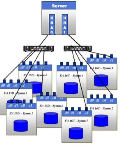
Example 2 In this example, as shown inFigure 2 on page 37, one host with two
HBAs is attached using a two-switch fabric to four Symmetrix arrays FA ports. In this configuration, the zones are created with one HBA and one FA port. That is,
◆ HBA0 is zoned to one 15D0 port on each of the four arrays.
Figure 2 One host, two switches, and four Symmetrix arrays
Note:All qualified HBAs are listed in theEMC Support Matrix.
When assigning Symmetrix LUNs to a VMware ESX Server host, the LUNs should be assigned to the host across both FAs since the Symmetrix is an active/active array.
The Symmetrix director ports are zoned to the HBAs on the switch. Devices can be added to the host using wither Symmetrix
Management Console (SMC) or Solutions Enabler.
Example for 4.x
Two HBAs with two paths each to the array totals four paths, and if using single initiator/single target zoning, there are four zones.
Note:It is recommended to choose "rule of 17" for Symmetrix connectivity (choose two FAs that add up to 17).
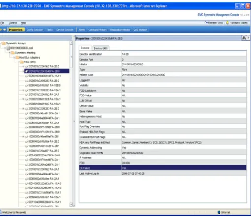
Once zoning is completed, use the Symmetrix Management Console (SMC) to verify that the initiators are visible on the console. SMC is a tool that is used to manage the Symmetrix. It can be used to map and mask the Symmetrix devices to the initiators.
Figure 3shows the screen used to verify the initiators are visible. When the initiator is chosen on the pane on the left-hand side of this window, the details of the initiator appear on the right. You must ensure that the parameterOn FabricshowsYes. This confirms that the zoning was successful.
Figure 3 SMC Properties verification screen
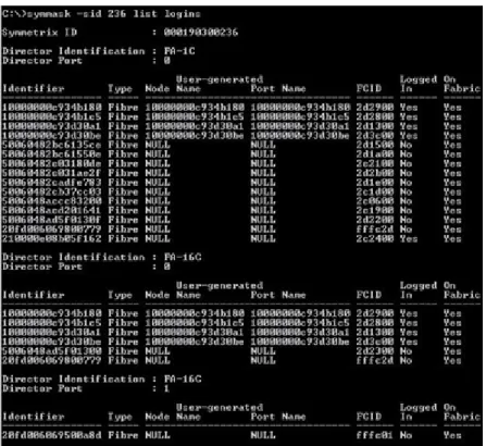
Another tool that can be used to monitor the Symmetrix is Solutions Enabler which, unlike the SMC, uses a command line interface (CLI).
Once the tool is installed on the ESX Server, the following command can be used to verify that the zoning was successful:
# symmask -sid <last 3 digits of the symm frame> list logins -dir <dir#> -port <port#>
InFigure 4, the initiators that have been zoned are listed. Under the
On Fabriccolumn heading you must seeYeslisted beside your initiators to verify zoning.
Figure 4 Solution Enabler CLI verification screen Verification of zoning
from initiator side
From the host side, running the following commands lists the details of the initiator ports:
◆ For Emulex HBA:
#cat /proc/scsi/lpfcdd/N
◆ For QLogic HBA:
#cat /proc/scsi/qla2xxx/N
These commands also lists the WWNs and WWPNs of the array ports that the host has been zoned to.
For example:
@@@@@ cat /proc/scsi/lpfc820/6
Emulex LightPulse Fibre Channel SCSI driver 8.2.0.30.49vmw
Emulex LP21000-M 10GE PCIe FCoE Adapter on PCI bus 0b device 00 irq 137 BoardNum: 0
Firmware Version: 1.00A5 (A3D1.00A5)
Portname: 10:00:00:00:c9:3c:f8:1c Nodename: 20:00:00:00:c9:3c:f8:1c SLI Rev: 3
NPIV Supported: VPIs max 100 VPIs used 0 RPIs max 512 RPIs used 7
Vport List: Link Up - Ready:
PortID 0x230015 Fabric
Current speed 4G
Physical Port Discovered Nodes: Count 2
t01 DID 241b00 State 06 WWPN 50:06:04:82:d5:f0:c8:d1 WWNN 50:06:04:82:d5:f0:c8:d1 t00 DID 282d00 State 06 WWPN 50:06:04:82:d5:f0:c8:de WWNN 50:06:04:82:d5:f0:c8:de
The WWPNs and WWNs of the array ports are bolded.
VNX series and CLARiiON connectivity
Note:Refer to theEMC Support Matrixor contact your EMC representative for the latest information on qualified hosts, host bus adapters, and connectivity equipment.
EMC Access Logix™must be installed on the VNX series and
CLARiiON storage system to which the VMware ESX Server is being attached.
VMware ESX Server uses the Linux version of the Navisphere Agent CLI. The Naviagent must be loaded on the Service Console of the ESX Server while the Naviagent CLI is supported on both the Service Console and the Virtual Machines.
In VMware ESX Server 4.x, both native multipath software and EMC PowerPath®/VE automatically perform registration to VNX series
and CLARiiON systems. Unisphere/Navisphere Agent is not required on VMware ESX Server 4.x.
VMware ESX Server owns the HBAs, not the operating systems running in the virtual machines. As a result, the VMware ESX Server's HBAs will be registered on the VNX series and CLARiiON system and assigned to a Storage Group.
The virtual machines will be assigned LUNs through the VMware ESX Server Service Console.
The following are two examples of zoned hosts:
◆ “Example 1” on page 41 ◆ “Example 2” on page 43
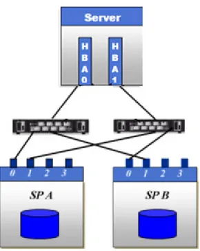
Example 1 In this example, as shown inFigure 5 on page 42, one host with two
HBAs is attached to one VNX series or CLARiiON system using two separate switches. Two SP ports on each SP within the systems are being used. HBA0 is zoned to SPA0 and to SPB1. HBA1 is zoned to SPA1 and to SPB0. The zones should be composed of a single initiator and a single target so they would be created with one HBA and on SP port. Two HBAs with two paths each to the systems totals four paths and if using single initiator/single target zoning, there are four zones. In this particular example, two switches are used. Using only one switch is supported, but such a configuration would lack
redundancy. Preferably, a minimum of two switches should be used as this adds another level of redundancy. Alternatively, for additional redundancy, two separate fabrics can be utilized.
Example 2 In this example as shown inFigure 6, one host with two HBAs is attached using a two-switch fabric to four VNX series or CLARiiON system SPs. In this configuration, the zones are created with one HBA and one SP port. For instance:
◆ HBA0 is zoned to one SPA port on each of the four systems.
◆ HBA1 is zoned to one SPB port on each of the four systems.
Figure 6 One host, two switches, and four VNX series or CLARiiON systems
Note:All qualified HBAs are listed in theEMC Support Matrix.
When assigning VNX series or CLARiiON LUNs to a VMware ESX Server host, the LUNs may be assigned to only one SP or their assignments may be split between the two SPs. Either configuration is valid.
Identifying the WWNs of the HBAs
◆ The recommended method to discover WWNs is to run the
wwpn.plcommand for either QLogic or Emulex HBAs. For each vmhba instance, thewwpn.plwill provide the corresponding QLogic or Emulex WWPNs.
For example:
[root@l82bi199 /]# /usr/sbin/wwpn.pl vmhba2: 210000e08b0910a7 (QLogic) 6:1:0 vmhba3: 210100e08b2910a7 (QLogic) 6:1:1
◆ An alternate method to obtain Emulex HBAs’ initiator and target information is to refer to /proc/scsi/lpfcdd/N(whereN
indicates the file for each adapter in the system) when the driver is loaded. Bygrep’ing the file(s), the necessary information to register to host will be reported.
grepthe file to obtain the initiator and target information. For example,
grep DID /proc/scsi/lpfcdd/1
produces output similar to the following for the first Emulex HBA:
lpfc0t00 DID 060300 WWPN 50:06:01:61:10:60:12:5c WWNN 50:06:01:60:90:60:12:5c lpfc0t01 DID 060400 WWPN 50:06:01:69:10:60:12:5c WWNN 50:06:01:60:90:60:12:5c ◆ When using QLogic HBAs, the same information is logged in
/proc/scsi/qla2x00/N(whereNindicates the file for each adapter in the system) when the driver is loaded.
grepthe file to obtain the initiator and target information. For example, for a host with QLA23xx HBAs:
grep scsi-qla /proc/scsi/qla2300/0
produces output similar to the following for the first QLogic HBA: scsi-qla0-adapter-node=200000e08b0910a7; scsi-qla0-adapter-port=210000e08b0910a7; scsi-qla0-target-0=5006016810601270; scsi-qla0-target-1=5006016010601270; scsi-qla0-target-2=50060160082012bb; scsi-qla0-target-3=50060169082012bb;
Now that the WWNs have been identified, the VMware ESX Server host can be registered to the VNX series or CLARiiON system.
The following section will describe the manual registration process.
Manually register the host
In order to manually register the host on the VNX series or CLARiiON system, perform the following steps:
1. Start the management interface in a web browser on a host to be used for management purposes.
2. Select theStoragetab so that the arrays being managed by the management interface are displayed.
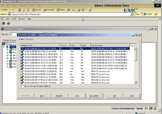
3. Right-click on the appropriate array and select theConnectivity Statusoption.
4. TheConnectivity Statusdialog for that array will show the Initiator WWNs for each host logged into the array.
An example of theConnectivity Statusdialog box can be seen in
Figure 7 on page 45.
5. In order to manually register your host’s HBAs, select the WWN of the HBA and click onRegister.
You will be prompted to add the server information, such as the server name and IP address.
Repeat this step for each HBA instance for this VMware ESX Server host. This will register this HBA or HBAs for your VMware host.
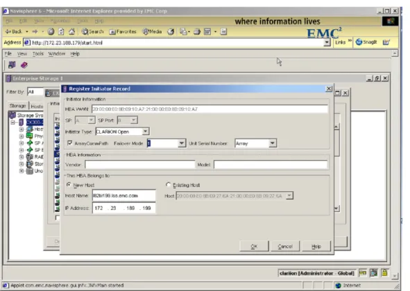
6. Another dialog,Register Initiator Record, appears. When attaching a VMware ESX Server to a VNX series and CLARiiON, the standard. For afailover-enabledenvironment, the required settings are as follows:
• Initiator Type: CLARiiON Open • ArrayCommPath: Enabled • FailOverMode: 1
• Unit Serial Number:Array
Note that the failover functionality referred to here is the native failover functionality incorporated into the VMkernel, not PowerPath. PowerPath is not available for the VMkernel.
Figure 8 on page 47shows an example of registering for a failover-enabled environment.
Note:The box for the ArrayCommPath parameter is checked and the Failover Mode is set to1.
Figure 8 Registering for a failover-enabled environment example
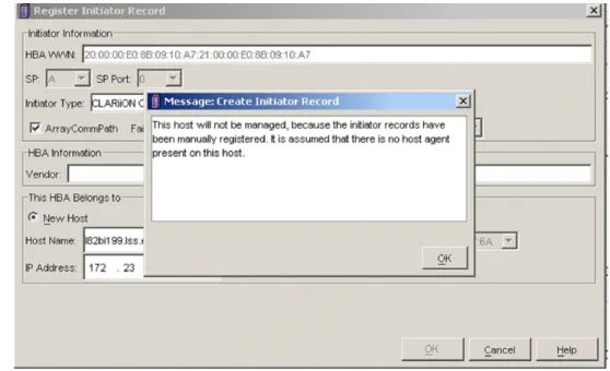
Because no Naviagent is used on the VMware ESX Server, you will receive a warning message when registering the host.
Figure 9 Warning message example
Because the Naviagent is not being used, this warning is to be expected and is acceptable.
7. RepeatStep 1throughStep 4for each HBA in the VMware ESX Server system.
8. To verify that your host has been properly registered, right click on the array and go to theHoststab.
The host will be reported as attached, but manually registered as in the example of the system namedl82bi199.lss.emc.comas
iSCSI
The Internet Small Computer Systems Interface (iSCSI) protocol enables the transport of SCSI blocks through TCP/ IP network. iSCSI works by encapsulating SCSI commands into TCP packets and sending it over IP network. An example is shown inFigure 11.
Figure 11 SCSI commands encapsulated by Ethernet headers
iSCSI is IP-based traffic and therefore can be routed or switched using standard (10 Mb/s, 100 Mb/s, 1 G, 10 G) Ethernet equipment. Traditional Ethernet adapters (NICs) are designed to transfer packetized file level data among PCs, servers, and storage devices, such as NAS appliances.
In order for NIC to process block level data, the data needs to be placed into a TCP/IP packet before being sent over the IP network. This block level data packet creation and TCP/ IP processing is done through the use of iSCSI drivers. The process, known assoftware (SW) iSCSI, is extremely CPU intensive and lowers the overall server performance. SW iSCSI doesnotsupport boot from SAN. For more information on SW iSCSI, refer to“VMware ESX SW iSCSI” on page 51.
The TCP/IP processing performance bottleneck has been the driving force behind the development of TCP/IP offload engines (TOE) on adapter cards. A TOE removes the TCP/IP processing from the host CPU and completes TCP/IP processing and packet creation on the HBA. Thus, a TCP/IP offload storage NIC operates more like a storage HBA rather than a standard NIC. This is often referred to as
hardware (HW) iSCSI. HW iSCSI supports boot from SAN. For more information on SW iSCSI, refer to“VMware ESX SW iSCSI” on page 51.
The setup of ESX server differs between SW and HW iSCSI. ESX Server does not support both hardware and software initiators running simultaneously.
Note:Refer to theEMC Support Matrixfor supported HW iSCSI initiators.
Always ensure that the hardware iSCSI initiators are successfully installed and recognized by the system.
VMware ESX SW iSCSI
This section describes the steps required to configure SW iSCSI initiator ports.
Note:SW iSCSI does not support boot from SAN. iSCSI traffic should be isolated from other network traffic.
ESX 3.x SW iSCSI support
◆ Supports only send targets discovery
◆ Requires both VMkernel port and service console to be on the same vSwitch, as shown inFigure 12
Figure 12 VMkernel and service console on a single vSwitch ◆ Supports NIC-teaming
While configuring a software iSCSI initiator using NICs, VMware recommendsNIC-teamingto provide failover between multiple NICs, which means the NICs are on the same vSwitch using the same IP address.
ESX 4.x and ESXi 5.0 SW iSCSI support
◆ Supports both send and static targets discovery
◆ Requires only VMkernel port to be in the network configuration
◆ Supports NIC-teaming
◆ Supports ALUA, failover mode 4 for VNX series and CLARiiON system
◆ Supports EMC Powerpath/VE
Note:For more information about EMC PowerPath/VE, refer to
http://www.emc.com.
Setting up SW iSCSI
To set up the SW iSCSI initiator, complete the following steps.
Note:Some steps are optional, as noted, depending on the ESX version used.
Each step is outlined in more detail in this section: 1. “Set up VMkernel” on page 52
2. “Set up the service console (optional for ESX 4.x; not applicable for ESXi 5.0)” on page 54
3. “Enable the SW iSCSI configuration” on page 55
4. “Add send targets” on page 55
5. “Add static targets (not applicable for ESX 3.5)” on page 55 Set up VMkernel
To set up the VMkernel, complete the following steps: 1. Log in to the VMware VI client as administrator.
2. From the inventory panel, select the server to be configured. 3. Click theConfigurationtab and clickNetworking.
4. ClickAdd Networking.
5. InConnection Type, selectVMkerneland clickNext. TheNetwork Accesspage displays.
6. Either select an existing vSwitch or clickCreate a virtual switch.
Note:iSCSI traffic should be separated from other network traffic.
7. Check the box next to each adapter that you want to connect to the vSwitch.
TheVMkernel Connection Settingswindow displays. The adapters that you select should appear in thePreviewpanel, as shown in the next figure.
8. ClickNext.
9. UnderPort Group Properties, select or enter a network label. 10. UnderIP Settings, enter the adapter IP address and subnet mask
for VMkernel.
11. Set theVMkernel Default Gateway. This must be a valid address.
12. ClickNext.
13. Review theSummaryand if all of the settings are correct, click
Finish.
14. For ESX 4.x and ESXi 5.0 only, to verify SW iSCSI initiator network has been correctly setup, open a console window by issuing the following command:
# vmkping <target_ip_address>
For ESX 3.x, proceed to“Set up the service console (optional for ESX 4.x; not applicable for ESXi 5.0)” on page 54. ESX 3.x requires a vmkiscsid daemon which resides in the service console) to initiates sessions and handles login and authentication. The actual I/O goes through VMkernel.
Set up the service console (optional for ESX 4.x; not applicable for ESXi 5.0)
To set up the service console, complete the following steps:
1. InConfigurationtab, networking section, under the vSwitch that was created, clickPropertiesand then clickAdd.
2. InConnection Type, selectService Consoleand clickNext. TheAdd Network Wizarddialog box appears, as shown in the next figure.
3. UnderPort Group Properties, select or enter a network label. 4. UnderIP Settings, enter the adapter IP address and subnet mask
for the service console.
5. Set theService Console Default Gateway. 6. ClickNext.
7. Review theSummaryand if all of the settings are correct, click
Finish.
8. To verify SW iSCSI initiator network has been correctly set up, open a console by issuing the following command:
# vmkping <target_ip_address>
You should be able to get response from the target.
Enable the SW iSCSI configuration
1. Click theConfigurationtab and then clickStorage Adapters.
2. SelectSW iSCSI adapterand then clickProperties. 3. Under theGeneraltab, clickConfigure.
4. UnderStatus, check the box next toEnabled. 5. If required, amend the iSCSI name and clickOK.
Add send targets
Note:This steps is optional for ESX 4.x and ESXi 5.0, which may use Add static targets.
Add target addresses for the hardware initiator.
Note:Both send and static targets discovery are supported.
To add send targets:
1. Click theConfigurationtab and then clickStorage Adapters. 2. SelectSW iSCSI adapterand then clickProperties.
3. Click theDynamic Discoverytab and then clickAdd. 4. Enter the send targets server IP and clickOKto add target
information from a selected storage system.
Add static targets (not applicable for ESX 3.5)
Note:ESX 4.x and ESXi 5.0 can use either Add Send targets or Add Static Targets.
1. Click theConfigurationtab and then clickStorage Adapters. 2. SelectSW iSCSI adapterand then clickProperties.
3. Click theStatic Discoverytab to add static targets and then click
4. Enter the send targets server IP, port, and iqn address and click
OKto add the static targets.
5. ClickCloseto close theiSCSI Initiator Propertiespage.
Once the iSCSI initiator ports on the ESX Server are configured, iSCSI storage must be presented to the ESX Server. Refer to the latestEMC Support Matrixfor the most up-to-date information on which EMC arrays that are supported via iSCSI attach to VMware ESX Server 3.x and 4.x.
Enable services and agents in the initiator firewall
Configure the service console firewall to accept services and installed management agents, enabling the services and agents to access the ESX Server, by completing the following steps:
1. Log in to the VMware VI client as administrator.
2. In the VI Client, underHosts and Clusters, click the server. 3. Click theConfigurationtab and then clickSecurity Profile. 4. ClickPropertiesto open theFirewall Propertiesdialog box.
This dialog box lists services and management agents. 5. If not already checked, enable the software iSCSI Client by
checking the box. 6. ClickOK.
Once the iSCSI initiator ports on the ESX Server are configured, iSCSI storage must be presented to the ESX Server. Refer to the latestEMC Support Matrixfor the most up-to-date information on which EMC arrays that are supported via iSCSI attach to VMware ESX Server 3.x.
Network configurations for ESX 4.x and ESXi 5.0
In a two or more NICs’ environment, SW iSCSI may be set up through the use of a single vSwitch or dual vSwitch network configuration, as shown inFigure 13 on page 57.
In ESX 4.x and ESXi 5.0, a single vSwitch containing two NICs can be configured to use NIC teaming or port binding to provide failover capabilities. Port binding can be enabled by overriding vSwitch failover order such that each NIC is only bound to one VMkernel port. Refer to“Set up 1:1 VMkernel to network adapters mapping” on page 61for steps to perform port binding.
Note:EMC recommends having the two NICs/ VMkernel ports are on different subnets. Ensure the SP ports belonging to the same Storage Processor are also on different subnets.
Likewise, two vSwitches can be created on ESX 4.x and ESXi 5.0 and each vSwitch can be bound to one or more NICs, as shown in
Figure 14.
Figure 14 Two NICs in dual vSwitch iSCSI configuration
Setting up multipathing with all iSCSI adapters on a single vSwitch for ESX 4.x and ESXi 5.0
To set up multipathing with all iSCSI adapters on a single vSwitch for the ESX 4.x and ESXi 5.0, the following steps must be completed. Each step is outlined in more detail in this section:
1. “Add iSCSI adapters to existing vSwitch” on page 59
2. “Set up 1:1 VMkernel to network adapters mapping” on page 61 Figure 15 on page 59shows an example of a vSwitch configuration.
Figure 15 vSwitch configuration
Add iSCSI adapters to existing vSwitch
To add iSCSI adapters to an existing vSwitch, complete the following steps:
1. Log in to the VMware VI client as administrator.
2. From theinventorypanel, select the server to be configured. 3. Click theConfigurationtab and clickNetworking.
4. InConfigurationtab,Networkingsection, under the vSwitch that was just created, clickProperties.
TheAdapter Selectionwindow displays, as shown in the next figure.
6. Check the box next to each adapter that you want to connect to the vSwitch and clickNext.
7. ClickNext.
8. Review theSummaryand if all of the settings are correct, click
Set up 1:1 VMkernel to network adapters mapping
To set up 1:1 VMkernel to network adapters mapping, complete the following steps:
1. In thevSwitch Propertieswindow, shown in the next figure, select theVMkerneland clickEdit.
2. Select theNIC Teamingtab and check the boxOverride vSwitch failover order:,as shown in the next figure.
3. Set one active adapter for each VMkernel and move the rest of the adapters toUnused Adapters.
Repeat this step for every VMkernel on the vSwitch.
Note:There should be the same number of VMkernel and Network adapters.
4. Activate host-based multipathing by connecting each VMkernel ports e.g., vmk0 and vmk1, to the iSCSI initiator from the service console by issuing the following commands:
• For vSphere 4:
# esxcli swiscsi nic add -n vmk0 -d vmhba32 # esxcli swiscsi nic add -n vmk1 -d vmhba32 # esxcli swiscsi nic list -d vmhba32
• For vSphere 5:
# esxcli iscsi networkportal add -n vmk0 -A vmhba32 # esxcli iscsi networkportal add -n vmk1 -A vmhba32 # esxcli iscsi networkportal list -A vmhba32
Both vmk0 and vmk1 should be listed and there should be two separate paths to the same target.
5. To remove VMkernel ports from iSCSI initiators, ensure there are no active session between hosts and targets, and run the
following command from service console: • For vSphere 4:
# esxcli swiscsi nic remove -n vmk0 -d vmhba32
• For vSphere 5:
# esxcli iscsi networkportal remove -n vmk0 -A vmhba32
VMware ESX HW iSCSI
This section contains information on the VMware ESX HW iSCSI.
ESX 3.X HW iSCSI support
Supports both send and static targets discovery
ESX 4.x and ESXi 5.0 HW iSCSI support
◆ Supports both send and static targets discovery
◆ Supports ALUA mode, failover mode 4 for VNX series and CLARiiON systems
◆ Supports EMC PowerPath/VE
Note:For more information about EMC PowerPath/VE, refer to
http://www.emc.com.
Configuring HW iSCSI initiator
To configure ESX/ESXi hardware initiator (iSCSI HBA), complete the following steps:
1. Log in to the VMware VI/vSphere client as administrator. 2. From the inventory panel, select the server to be configured. 3. Click theConfigurationtab, and clickStorage Adapters. 4. Select HW iSCSI initiator to configure, and clickProperties. 5. In the HWiSCSI Initiator Propertiespage, click theGeneraltab
and then clickConfigure.
6. UnderiSCSI Properties, can enter aniSCSI nameandiSCSI Aliasfor the hardware initiator and then clickOK.
7. UnderHardware Initiator Properties, add IP settings for the initiator.
8. Add target addresses for hardware initiator, both send and static targets discovery are supported:
a. Click theDynamic Discoverytab, to add send targets, and then clickAdd.
b. Enter the send targets server IP and clickOKto add target information from a selected storage system.
Or
a. Click theStatic Discoverytab, to add static targets, and then clickAdd.
b. Enter the send targets server IP, port, and iqn address and clickOKto add
9. ClickCloseto close theiSCSI Initiator Propertiespage.
Once the iSCSI initiator ports on the ESX Server are configured, iSCSI storage must be presented to the ESX Server. Please refer to the latest EMC Support Matrixfor EMC arrays that are currently supported through iSCSI attach to VMware ESX Server 3.x and 4.x.
Symmetrix connectivity
The following bit settings are required on the director ports for ESX/ESXi operations:
◆ Common serial number (C)
◆ SCSI 3 (SC3) set (enabled)
◆ SPC-2 (Decal) (SPC2) SPC-2 flag is required
The bit settings can be configured using EMC Symmetrix Management Console or Solutions Enabler. Refer to“Symmetrix array configurations” on page 94for more details.
This section details the steps needed for:
◆ “Using Solution Enabler” on page 65
◆ “Using Symmetrix Management Console (SMC)” on page 66 Using Solution Enabler
To use Solution Enabler, complete the following steps: 1. Install Solution Enabler for ESX host.
Note:A license is required.
2. Go to the default location:
cd /opt/emc/SYMCLI/V6.5.1/bin
3. Run#./symcfg discover.
4. Subsequently, run#./symcfg list.
5. Ensure the attached Symmetrix have a local attachment.
6. Verify the ESX host is visible to the array by issuing the following command:
#./symmask -sid <last 3 digits of the symm frame> list logins -dir <dir number>
-p <port number> | more
A initiator will be shown asLogged Inafter a LUN has been masked to the initiator. Refer to the EMC Symmetrix Management Console Online Help for information on how to mask a LUN.
Using Symmetrix Management Console (SMC)
To use the SMC, complete the following steps: 1. Log in to the SMC from a browser.
Note:Disable pop-up blockers.
2. Expand theSymmetrix Arraysfolder on the left panel and then select the array connected.
3. Expand theSymmetrix Maskingfolder. 4. Expand theHost Bus Adaptersfolder. 5. Expand theiSCSIfolder.
The initiator should be listed with a record for every target connected. Ensure that the HBA and Port Flags in effect are correctly set.
Similarly, an initiator will be shown asLogged Inonly after a LUN has been masked to the initiator, as shown in the next figure. Refer to Symmetrix Management Console online help available on onhttp://support.EMC.comfor information about how to mask a LUN.
VNX series and CLARiiON connectivity
For a failover-enabled environment, the required settings are as follows:
◆ Initiator Type: CLARiiON Open
◆ ArrayCommPath: Enabled
◆ FailOverMode: 1
◆ Unit Serial Number: Array
Note:The failover functionality referred to here is the native failover functionality incorporated into the VMkernel.
In order to manually register the host, you must first identify the iqns of the initiators. iSCSI name and iqn refers to the same thing. The iqn
is used when registering the VMware ESX Server host onto the VNX series and CLARiiON systems. The iqn can be found from VI/ VSphere clientInventorypanel >Configurationtab,Storage adapters.
To manually add VMware ESX host to VNX series and CLARiiON, complete the following steps:
1. Log in to the management interface from a browser.
Note:Java is required.
2. Select theStoragetab, right-click on the appropriate array, and select theConnectivity Statusoption, as shown in the next figure.
3. Select the initiator iqn from the list, in theConnectivity Status
dialog box.
4. ClickRegister, or clickNewif the initiator record cannot be found.
TheCreate Initiator Recorddialog box displays whenNewis clicked, as shown in the next figure.