Clemson University
TigerPrints
All Theses
Theses
12-2012
An efficient image segmentation algorithm using
bidirectional Mahalanobis distance
Rahul Suresh
Clemson University, [email protected]
Follow this and additional works at:
https://tigerprints.clemson.edu/all_theses
Part of the
Computer Sciences Commons
This Thesis is brought to you for free and open access by the Theses at TigerPrints. It has been accepted for inclusion in All Theses by an authorized administrator of TigerPrints. For more information, please [email protected].
Recommended Citation
Suresh, Rahul, "An efficient image segmentation algorithm using bidirectional Mahalanobis distance" (2012).All Theses. 1556.
An efficient image segmentation algorithm using
bidirectional Mahalanobis distance
A Dissertation Presented to the Graduate School of
Clemson University
In Partial Fulfillment of the Requirements for the Degree
Master of Science Electrical Engineering by Rahul Suresh December 2012 Accepted by:
Dr. Stanley Birchfield, Committee Chair Dr. Brian Dean
Abstract
In this thesis, we present an efficient graph-based image-segmentation algorithm that im-proves upon the drawbacks of the minimum spanning tree based segmentation algorithm [9], namely leaks that occur due to the criterion used to merge regions, and the sensitivity of the output to the parameterk. To address these problems, we propose the use of bidirectional Mahalanobis distance, along with a Gaussian model for each region, and an intuitive normalized parameterτthat replacesk
and works for all images without having to be changed. Furthermore, we propose an approximation to the algorithm that enables it to run efficiently in O(N logN) time (N represents the number of pixels in the image), without compromising on the performance. Experiments on a wide variety of images demonstrates the ability of the algorithm to achieve accurate results in an efficient manner.
Dedication
Acknowledgments
I would firstly like to express my sincere gratitude towards my advisor Dr.Birchfield, without whom this thesis would not have been possible. His support and guidance was always inspiring.
I would also like to convey by gratitude towards Dr.Dean and Dr.Hoover for agreeing to serve in my committee and for their valuable feedback.
I would also like to acknowledge JungPhil Kwon for participating in our research meetings and brainstorming ideas. Additionally, I would like to thank all the members of the computer vision research group at Clemson University for creating an inspirational research environment.
Last but not the least, I would like to thank all my friends at Clemson who have supported me- Shivram, Sumod, Vibhor, Balu, Aditya, Darshana, Pallavi and Neeraja.
Table of Contents
Title Page . . . i
Abstract . . . ii
Dedication . . . iii
Acknowledgments . . . iv
List of Figures . . . vii
1 Introduction . . . 1
1.1 Image segmentation . . . 1
1.2 Applications of image segmentation . . . 2
1.3 What defines a good segmentation? . . . 3
1.4 Thesis outline . . . 4
2 Related Work . . . 6
2.1 Split and merge approaches . . . 6
2.2 Clustering and mean shift segmentation . . . 6
2.3 Spectral graph theory and normalized cuts . . . 7
2.4 Minimum spanning tree based segmentation . . . 8
3 Background theory . . . 10
3.1 Image as a graph . . . 10
3.2 Minimum Spanning Tree . . . 11
3.3 Minimum spanning tree segmentation algorithm . . . 12
3.4 Results and Drawbacks . . . 16
4 Proposed Algorithm . . . 18
4.1 Constructing the image grid . . . 18
4.2 Region growing . . . 20
4.3 Updating weights in the list . . . 24
4.4 Approximation . . . 24
4.5 Pseudocode . . . 25
5 Results . . . 27
5.1 Results on synthetic images . . . 27
5.2 Analysis of optimal segmentation . . . 28
5.3 Results on the BSDS dataset . . . 29
6 Conclusions and Discussion . . . 48
List of Figures
1.1 Example of image segmentation. a) Original image b) Segmented image [20] . . . . 2
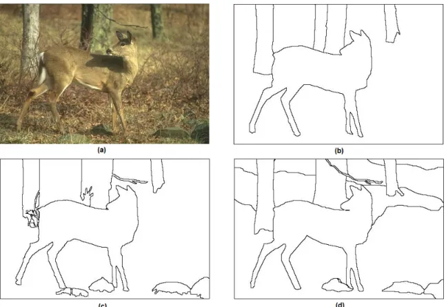
1.2 (a) Deer image (b),(c),(d) Manual segmentation performed by various human subjects. Image courtesy- [20] . . . 4
3.1 The leak of the MST algorithm demonstrated on a synthetic image. a) Noisy image with 2 partitions and a thin grayscale ramp between them. b) MST result, in which the ramp enables the two sides to be merged despite their very differences in appearance. 17 3.2 Effect of the choice ofkon the granularity in the MST segmentation algorithm output. (a)-(d) MST results for various values of k, showing the difficulty of selecting the proper value. . . 17
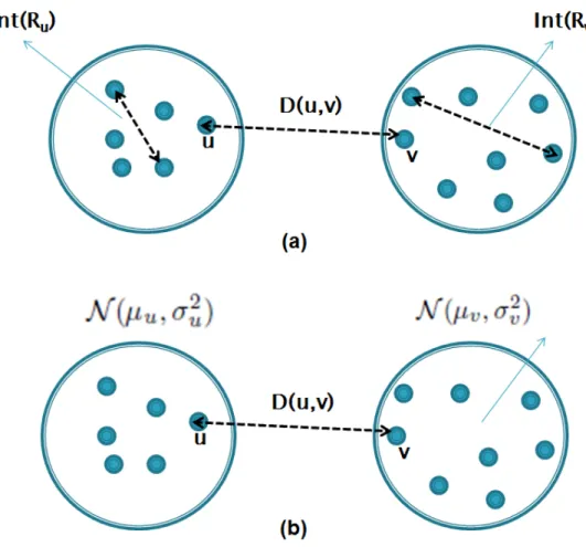
4.1 Criterion used for merging 2 regions a) MST algorithm compares the edge (u, v) with the maximum edge weights of regionsRu and Rv b) Our algorithm models Ru and Rv as Gaussian models and compares the Mahalanobis distance between them before merging. . . 22
5.1 The leak of the MST algorithm demonstrated on a synthetic image. a) Noisy image with 2 partitions and a thin grayscale ramp between them. b) MST result c) Our algorithm’s result . . . 28
5.2 (a) Gradient image (b) MST result (c) Our algorithm’s result . . . 28
5.3 Effect of the choice ofkon the granularity in the MST segmentation algorithm output. (a)-(d) MST results for various values of k, showing the difficulty of selecting the proper value. (e) Our algorithm for τ = 2.5, which is the same value used for all images, despite scene content and image size. . . 28
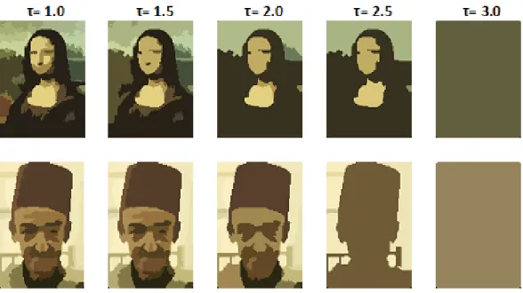
5.4 Our algorithm- different granularities of segmentation for a) Monalisa b) Man . . . . 29
5.5 Graph showing the relationship between threshold and number of components for Monalisa (TOP) and Man (BOTTOM) . . . 30
5.6 BSDS300 Segmentation Results (Mean Colors)- I[20] . . . 32
5.7 BSDS300 Segmentation Results (Contours)- I [20] . . . 33
5.8 BSDS300 Segmentation Results (Mean Colors)- II[20] . . . 34
5.9 BSDS300 Segmentation Results (Contours)- II [20] . . . 35
5.10 BSDS300 Segmentation Results (Mean Colors)- III[20] . . . 36
5.11 BSDS300 Segmentation Results (Contours)- III [20] . . . 37
5.12 BSDS300 Segmentation Results (Mean Colors)- IV[20] . . . 38
5.13 BSDS300 Segmentation Results (Contours)- IV [20] . . . 39
5.14 BSDS300 Segmentation Results (Mean Colors)- V[20] . . . 40
5.15 BSDS300 Segmentation Results (Contours)- V [20] . . . 41
5.16 BSDS300 Segmentation Results (Mean Colors)- VI[20] . . . 42
5.17 BSDS300 Segmentation Results (Contours)- VI [20] . . . 43
5.18 BSDS300 Segmentation Results (Mean Colors)- VII[20] . . . 44
5.20 BSDS300 Segmentation Results (Mean Colors)- VIII [20] . . . 46 5.21 BSDS300 Segmentation Results (Contours)- VIII [20] . . . 47
Chapter 1
Introduction
1.1
Image segmentation
Image segmentation refers to the process of dividing an image into components or regions such that the pixels within a region share certain visual characteristics with each other [10][27]. Math-ematically, image segmentation involves partitioning an imageIintoKcomponents-R1, R2, . . . , RK
such that:
R1∪R2∪R3. . .∪RK =I (1.1)
Ri∩Rj =φ ∀i, j:i6=j (1.2)
Each segmentRi is a subset of the imageI. Its size can be as small as one pixel (complete
segmen-tation) and as large as the entire image itself (no segmensegmen-tation).
1≤ |Ri| ≤ |I| ∀i (1.3)
A good segmentation algorithm would divide the image into segments of intermediate sizes such that similar objects or backgrounds are grouped together. Iff(Ri) represents a function that measures
whether regionRi is homogeneous or not, then a good segmentation algorithm would divide image
Figure 1.1: Example of image segmentation. a) Original image b) Segmented image [20]
f(Ri) = T RU E ∀i (1.4)
f(Ri∪Rj) = F ALSE ∀i, j:i6=j (1.5)
In other words, pixels within a region share certain visual traits that are not found in the pixels of another region. Figure 1.1 is a good illustration of image segmentation. Notice that pixels adjacent with similar color values are grouped together.
1.2
Applications of image segmentation
Image segmentation is a widely used technique and a major area of research in computer vision. It is used in a wide range of applications from lower level tasks such as finding connected components to higher level applications such as large-scale image classification systems.
Image segmentation is a very important preprocessing step in many biomedical analysis problems [3] [24] [21]. The requirements of biomedical segmentation varies widely depending on the modality of imaging used and the part of the body involved. However, in almost all cases, there is a need to segment various anatomical organs to facilitate further diagnosis and treatment. Image segmentation is also increasingly used these days in computer-guided surgery [12]. Image segmentation is seen as a very important preprocessing step in object recognition systems. Lower level features such as texture, color and intensity are used to segment the image into several regions. Relevant segments (or subset of pixels) are alone used by the recognition systems. This considerably saves the computational cost involved, especially when running on a large database [23]. Another important application where image segmentation is used extensively today is content based image retrival (CBIR) [7]. Some of the other areas where image segmentation is popular are face recognition [13], iris recognition [14], and astronomy [22].
1.3
What defines a good segmentation?
Consider the image containing the deer in Figure 1.2. Various human subjects were asked to manually segment the image. Notice that there is a lot of variation in the results. The number of segments is considerably higher in Figure 1.2-(d) than in Figure 1.2-(b). This variation in the segmentation results does not represent an an error in the output, but shows the varied levels of granularity perceived by the different human subjects [30]. In other words, we have many segmen-tations for the same image and all of them are “correct”. This ambiguity in defining “correctness” of segmentation makes the evaluation of segmentation algorithms difficult. Other areas in computer vision such as object detection and classification are well defined and hence no difficulty exists in evaluating them. This problem is unique to image segmentation [1] .
One of the primary objectives of this thesis is to address the above problem by defining “optimal” granularity and providing a mathematical intuition for it . Yu and Hoover have done extensive work in determining “stable” segmentation [32] [15]. They define stable segmentation as a configuration where the number of regions are least sensitive to parameter changes. The segmentation algorithm is run repeatedly on the same image for a wide range of its parameters and the best configuration is chosen based on the inavariance to parameter changes. We use a method
Figure 1.2: (a) Deer image (b),(c),(d) Manual segmentation performed by various human subjects. Image courtesy- [20]
along these lines to define “optimal” or “stable” granularity for our system.
1.4
Thesis outline
This thesis proposes an efficient image segmentation algorithm that runs real time and pro-duces good segmentation results. The mathematical justification for what constitutes the “optimal” granularity is also provided. Chapter 2 provides an overview about the various segmentation algo-rithms that are popular today and their relative merits and demerits. Emphasis is laid on graph based segmentation algorithms as it closely corresponds to this work. Chapter 3 provides a detailed background on the minimum spanning tree (MST) based segmentation algorithm. The major draw-backs of this algorithm are also discussed in detail. In Chapter 4, we introduce a novel, efficient, graph-based segmentation algorithm that improves upon the drawbacks of the MST algorithm. In Chapter 5, we discuss the results of our proposed segmentation algorithm. We validate its
perfor-mance by testing on a large database of images and comparing our algorithm to other segmentation algorithms. Chapter 6 provides a summary of this thesis work and possible future improvements.
Chapter 2
Related Work
There has been a considerable amount of research in the area of image segmentation. This chapter will provide an overview of some of the popular image segmentation techniques that exist today, with special emphasis on graph based approaches.
2.1
Split and merge approaches
Split and merge algorithms begin by considering the entire image as one region. The image is then iteratively split into regions based on the evidence of a boundary. The algorithms that follow this approach are generally based on quadtrees [28] [8] [16]. In the quadtree based approach, the im-age is recursively split into 4 equal sized regions based on the existance of non-uniformity in features and again recursively combined based on the existance of smilarities until a stable segmentation is obtained.
2.2
Clustering and mean shift segmentation
Another class of segmentation algorithm is based on clustering and mean shift. While clus-tering and mean-shift based methods are considered to be different algorithms, they still have a lot of underlying similarities. In the mean-shift segmentation algorithm, each pixel is represented as feature vector consisting of spatial and color components. The algorithm assumes that there is a probability distribution underlying the data. The modes of the distributon would represent the
centers of different regions. Each data point has a window defined around it and is shifted towards the mean of all the data points within that window. This is repeated iteratively until the data points converge to the modes of the distribution [4] [6].
Thek-means segmentation algorithm, as the name suggests, usesk-mean clustering to seg-ment data. Pixels are represented as vectors in ann-dimensional feature space. Feature space could be a combination of color and spatial information. k cluster centers are chosen randomly and each pixel is assigned to its closest cluster. Then the cluster means are recomputed. This process is repeated iteratively until the cluster centers converge. The main disadvantage of k-means is that the number of regions (clusters) must be known beforehand. Furthermore, the segmentation results are extremely sensitive to the initial choice of cluster centers. There is a lots of research happening of late that tries to address the above problems [33].
2.3
Spectral graph theory and normalized cuts
Another class of image segmentation algorithms seek to represent the image as a graph and find a “cut” that would partition the graph into different regions [19]. The objective of a graph cut problem is to find the set of edges to be removed such that similar vertices are grouped together. Consequently, the edges forming the cut should be the edges with the largest weights (lowest simi-larity).
Suppose we partition a graph G into disjoint setsS1 and S2. The objective of a min-cut
problem is to minimize the sum of the weights of edges that form the cut. We want to minimize the following function: f(S1, S2) = X i∈S1 X j∈S2 Wij (2.1)
The above optimization problem has a bias to create single node partitions. In order to ensure that reasonable sized partitions are obtained through the cut, the objective function that needs to be minimized is modified as follows:
RatioCut(S1, S2) = f(S1, S2) |S1| +f(S1, S2) |S2| (2.2)
Spectral graph theory based approaches including Normalized cuts use eigenvalues to find the graph partition [5] [31] [26] [29] [11]. The eigenvector of the Laplacian matrix L with second highest eigenvalue is chosen to form the cut .
L=D−W (2.3)
whereD is a diagonal matrix containing the row sums of the similarity matrixW.
Dii = X
j
Wij (2.4)
2.4
Minimum spanning tree based segmentation
Minimum spanning tree based segmentation algorithm is an efficient graph based segmen-tation algorithm [9]. It is a variant of Kruskal’s MST algorithm. In Kruskal’s algorithm, edgesE of the graphGare sorted in the non-decreasing order of their weights. These sorted edges are added to the minimum spanning tree in order as along as the new edge added does not form a cycle (thereby destroying the tree).
Kruskal’s algorithm adds all vertices of the graph Ginto one tree. However, the objective of the MST based segmentation algorithm is to obtainK trees from the graph G, where each tree would represent a region. In this algorithm, an undirected graph G = (V, E) is constructed by building an image grid or a nearest neighbor graph [9]. Pixels constitute vertices while edges are formed by connecting neighboring pixels in x−y space (image grid approach) or by connecting every pixel to its nearest neighbors in (x, y, R, G, B) space. The edges are sorted in non-decreasing order of weights. An approach similar to Kruskal’s minimum spanning tree algorithm is used to add vertices into the spanning tree. However, MST based segmentation algorithm adds an edge into a tree only if there is no evidence of boundary between the vertices forming the edge. In other words, regionsR1 andR2 are merged only if:
Dif f(R1, R2)<min Int(R1) + k |R1| , Int(R2) + k |R2| (2.5)
Dif f(R1, R2) is the weight of the edge under consideration. Int(R1) andInt(R2) refer to the
maxi-mum internal difference within the region (maximaxi-mum edge-weight) while |Rk| ensures that the merge criteria is relaxed for relatively small regions.
A forest of trees are obtained from the graph, where each tree represents a region in the image. The algorithm runs in O(N logN) time, N representing the number of pixels in the image. The primary drawbacks of the algorithm include its sensitivity to parameterkand also the problem of “leak”. Since this algorithm is very closely related to this thesis, a very detailed description has been provided in Chapter 3.
Chapter 3
Background theory
3.1
Image as a graph
A graph G= (V, E) is an abstract data type containing a set of vertices V and edges E. Vertices, often called nodes, are connected to each other through edges. A weight is associated with every edge in the graph and its value depends on the degree of similarity/ dissimilarity between the nodes connected by it. The list of edges between the various vertices are represented using Adjacency Matrix for a dense graph and Adjacency list for a sparse graph. Several useful operations can be performed on a graph. These include:
1. Checking if a path exists between verticesvi andvj.
2. Finding the connected components in a graph.
3. Finding the strongly connected components in a graph
4. Determining if a cycle exists in the graph
5. Computing the shortest path between verticesvi andvj.
6. Computing the minimum spanning tree
7. Partitioning a graph into various regions using graph-cut algorithms.
Graph techniques have become very popular in computer vision. In the graph representation of an image, a single pixel or a group of pixels normally form the vertices while the degree of dissimilarity
between the vertices determines the weight associated with the edges. There are multiple ways to construct an image graph. These include:
1. Image grid: In this scheme, every pixel is assigned to a vertex in the graph. Edges are connected between adjacent pixels inx−yspace, thereby creating a grid. The weight associated with the edges is normally the Euclidean distance between the pixels in color space. An advantage of this representation is that it is extremely easy to construct. Furthermore, the number of edges m = O(N), thereby by reducing the time complexity of algorithms that normally run inO(m) time. One of the main disadvantages of this representation is that an edge exists between two vertices only if they are adjacent in the x−y space, thereby global properties are often not captured while running a segmentation algorithm.
2. Complete graph: In a complete graph, there exists an edgeebetween every pair of vertices
vi, vj ∈ V. Thus, an image with n nodes would have O(N2) edges. The feature space for
computing the distance between the nodes forming an edge can beRGB color space orx−y
space or a combination of both. Most of the graph operations in this scheme would be very expensive.
3. Nearest neighbor graph: This representation acts as a comprimise between the image-grid representation (that fails to captures global properties in x−y space) and a complete graph (which has O(N2) edges). For every vertexvi ∈V, its k=O(1) neighbors are computed in
some feature space using Approximate Nearest Neighbors (ANN) algorithm [17]. (x, y, R, G, B) is an example of a 5-D features space that captures both color and spatial properties. Each vertex is then connected to itsknearest neighbors, thereby creating a graph that hasm=O(n) edges.
3.2
Minimum Spanning Tree
A tree is a connected graph with no cycles. Given a connected unweighted graphG= (V, E), a tree can be constructed using every vertex vi ∈ V such that there exists a path between every
pair of vertices. Such a tree is called a spanning tree. A graph can have many spanning trees. A spanning tree that is obtained by choosing a subset of edges from the graphG such that the sum of weights of the edges forming the spanning tree is minimal is called a Minimum Spanning Tree.
Kruskal’s [18] and Prim’s [25] algorithm are popularly used to find the minimum spanning tree of graphs. Kruskal’s algorithm has been discussed in the next section as it very closely relates to the image segmentation algorithm proposed in this thesis.
3.2.1
Kruskal’s Algorithm
In this algorithm, edges E of the graph G are sorted in the non-decreasing order of their weights. The sorted edges are added to the minimum spanning tree in the order of their weights as long as the new edge added does not form a cycle (thereby destroying the tree). In other words, we start off by considering graphGto be a forest ofN trees, each with exactly one node. After every iteration, two trees are merged as long as they do not form a cycle. This process is repeated until all the vertices of the graph are merged into one spanning tree. It can observed that the algorithm makes greedy choices at every stage to locally optimize the solution.
The pusedocode for the Kruskal’s algorithm is given below:
Kruskal(G= (V, E)) 1 he1, . . . , emi ←SortAscendingByWeight(E) 2 for(u, v)←e1 toemdo 3 u0←FindSet(u) 4 v0←FindSet(v) 5 if u0 6=v0 then 6 Merge(u0, v0)
There are three main operations in this algorithm- Sorting, FindSet and Merge. The FindSet and Merge operations can be accomplished in O(mα(N)) time, whereα is an extremely slow growing function called the inverse Ackermann function. The bottleneck in the algorithm is the initial sorting process, thus the overall time complexity isO(mlog(m)) time.
3.3
Minimum spanning tree segmentation algorithm
Felzenszwalb and Huttenlocher [9] proposed an efficient graph based agorithm that uses of a variant of Kruskal’s algorithm to segment images. The objective of Kruskal’s algorithm is to compute the minimum spanning tree of a weighted connected graph. However, if Kruskal’s algorithm were
directly applied to image segmentation, then we would end up with one image segment (consisting of the entire image). Thus, the objective of the MST based segmentation algorithm is modified to obtainK trees from the graphG. Each tree would represent a region in the image. Specific details about the algorithm are explained in the subsequent sub-sections.
3.3.1
Constructing the image graph
Given an imageI of size (w, h), we construct an image-grid Gas follows:
1. Every pixelI(x, y) is mapped with vertexvi∈V such that:
i= (y−1)∗w+x (3.1)
The information about the vertices are stored using a disjoint-set data structure D.
2. Edge setEis constructed by linking every vertexviwith its four immediate neighbors inx−y
space. The list of edges are maintained using an array.
3. The weightwiassociated with every edgeei∈Eis the Euclidean distance in theRGBfeature
space between the vertices ui, vi∈V that forms the edge.
Note that there areN nodes andm=O(N) edges in the graph.
3.3.2
Disjoint-set data structure
Information about vertices (or regions) are maintained using a disjoint-set data structure
D of sizeN. For every vertex vi, we store information about its root, size of the region to which
it belongs and the maximum edge weight in the region. During initialization of the image-gridG, every region consists of exactly one pixel. Information about vertexvi is stored at theith index of
D. D[i] is initialized as follow:
D[i].root=−1 (3.2)
D[i].numP ixels= 1 (3.3)
While the length of the disjoint set isN (corresponding to the number of pixels in the image), their values are stored, accessed and updated at their root vertices only. The root of any region Ri is
obtained using the following recursive algorithm:
getEquiv(i)
1 if equiv[i] ==−1 then
2 return(i) 3 else
4 return(getEquiv(equiv[i]))
3.3.3
Merge Criterion
As discussed in the previous section, every pixel is assigned to a seperate region in the image. The objective of the segmentation algorithm is to divide the image intoK regions such that 1 < K << N. First, the edges are sorted in the non-decreasing order of weights. An approach similar to Kruskal’s minimum spanning tree algorithm is used to add vertices into the spanning tree. However, MST based segmentation algorithm adds an edge into a tree only if there is no evidence of boundary between the vertices forming the edge. In other words, regionsRu andRv are merged
only if: D(Ru, Rv)<min Int(Ru) + k |Ru| , Int(Rv) + k |Rv| (3.5)
D(Ru, Rv) is the weight of the edge under consideration. Int(Ru) andInt(Rv) refer to the maximum
internal difference within the region (maximum edge-weight) while|Rk|ensures that the merge criteria is relaxed for relatively small regions. In other words, regionsRuandRvare merged only if the edge
weight connecting the regions is smaller than the the internal difference of both the components.
3.3.4
Merging regions
Merging can be easily accomplished using the disjoint set data structure. Suppose edge
ei ∈ E connecting verticesui, vi ∈ V is being added to the MST. Then the regions containingui
andvi can be merged by updating the disjoint set data structure as follows:
v0 =max(F indSet(u), F indSet(v)) (3.7)
D[v0].root=u0 (3.8)
D[u0].maxEdgeW eight=max(D[u0].maxEdgeW eight, D[v0].maxEdgeW eight) (3.9)
D[u0].numP ixels=D[u0].numP ixels+D[v0].numP ixels (3.10)
3.3.5
Pseudo code for the MST based segmentation algorithm
MST-Segmentation(I, k)
Input: image I, parameterk
Output: segmentationS
Data structures:
D is a DSDS with an element for each pixel in image
D[i] contains the base/root ID, max-edge-weight and number of pixels for vertexi
E is a vector of edges.
E[i] contains information about edgeei including the vertex ID’s and weight
1 D.Initialize(width∗height)
2 E←ConstructEdges(I)
3 he1, . . . , emi ←SortAscendingByWeight(E)
4 for(u, v)←e1 toemdo
5 u0←min (FindSet(u),FindSet(v)) 6 v0←max (FindSet(u),FindSet(v))
7 if u0 6=v0 and IsSimilar(u0, v0, w(u, v)) =T RU E then
8 Merge(u’,v’, w(u,v))
FindSet(u)
1 if D[u].root=−1 then
2 returnu
3 else
IsSimilar(u0, v0, w;k) 1 returnw <min D[u0].maxEdgeWeight+ k D[u0].numPixels,D[v 0].maxEdgeWeight+ k D[v0].numPixels DisjointSet:Initialize(N) 1 fori←0toN−1 do 2 D[i].root←i 3 D[i].maxEdgeWeight←0 4 D[i].numPixels←1 DisjointSet:Merge(u, v, w) 1 D[b].root ←a
2 D[a].maxEdgeWeight ←max(w,D[a].maxEdgeWeight,D[b].maxEdgeWeight) 3 D[a].numPixels ←D[a].numPixels+D[b].numPixels
3.4
Results and Drawbacks
MST algorithm runs in real time and uses greedy approach to achieve segmentation. The running time of this algorithm is O(mlog(m)) and since m = O(N), the asymptotic runtime is
O(N logN). Some of the drawbacks of MST based segmentation are:
1. The use of minimum edge weight to determine whether to merge regions or not. This can often lead to faulty segmentations when there is a leak. (See Figure 3.4).
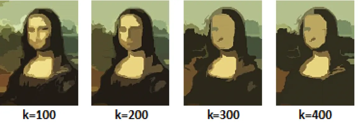
2. Its sensitivity to parameter k that determines the granularity of segmentation. This is again apparent in Figure 3.2
In this thesis, we propose a graph based segmentation algorithm that improves upon the shortcomings of the MST segmentation. There are two primary contributions in this thesis. Our first main contribution is the use of bidirectional Mahalanobis distance to determine the existance of a boundary. Within the framework of the MST based approach, we represent every image region as a Gaussian distribution. Edges are added to a tree only if the Mahalanobis distance between the Gaussian distributions is less than a predetermined value. This ensures that region merging does not happen when there is a “leak” from one region to another.
Figure 3.1: The leak of the MST algorithm demonstrated on a synthetic image. a) Noisy image with 2 partitions and a thin grayscale ramp between them. b) MST result, in which the ramp enables the two sides to be merged despite their very differences in appearance.
Figure 3.2: Effect of the choice ofkon the granularity in the MST segmentation algorithm output. (a)-(d) MST results for various values ofk, showing the difficulty of selecting the proper value.
The second contribution in this thesis is to provide an inituition regarding the granularity of segmentation. In the MST algorithm, the value of kis chosen arbitrarily. Any change in k can affect the granularity of segmentation significantly. Furthermore, kis dependent on the size of the image. We propose the use a thresholdτ that would depend on the Mahalanobis distance between the Gaussian distributions. Mahalanobis distance is similar to Euclidean distance but is normalized byσ. We show that stable segmentations are obtained for 2< τ <2.5, which sounds mathematically justifiable. The details about this new algorithm is provided in the next chapter.
Chapter 4
Proposed Algorithm
In this chapter, we propose an efficient graph-based segmentation algorithm that would improve upon the problems associated with the MST based segmentation approach- namely its sensitivity to parameterkand the criterion used to merge regions. Later on, we propose an approxi-mation that would enable the algorithm to run in real-time while still improving upon the problems associated with the MST based approach.
4.1
Constructing the image grid
4.1.1
Initialize vertices
V
Given an imageI withN pixels, we want to create a segmentationS consisting of regions
S= (R1, R2, . . . , RK). We begin by constructing an image-grid graphG= (V, E), where every pixel
I(x, y) is mapped to a vertexvi∈V such that:
i= (y−1)∗w+x (4.1)
The information about vertices (or regions) are maintained using a disjoint-set data structureD of size N. Information about every vertexvi such as its root node, zeroth-, first- and second- order
moments are stored at theith index ofD. During initialization of the image-gridG, every region consists of exactly one pixel. Thus,D[i] is initialized as follows:
D[i].root=−1 (4.2)
D[i].zerothM oment= 1 (4.3)
D[i].f irstM oment={v[i].r, v[i].g, v[i].b} (4.4)
D[i].secondM oment={v[i].r2, v[i].g2, v[i].b2} (4.5)
4.1.2
Initialize edges
E
Edges are created by connecting every pixel to its 4 immediate neighbors. Thus, the number of edgesm=O(N). Every edgeei connects verticesui, vi∈V and has a weightwi associated with
it. The edges are stored as a doubly linked list. Each item in this linked list is a structwith the following members:
struct Edge {
int u; //vertex u
int v; //vertex v double w; //edge weight
Edge *previous; //pointer to the previous edge in the list Edge *next; //pointer to the next edge in the list
}
Note that there arem=O(N) number of edges in the list.
4.1.3
Initialize edge weights
The weight of an edgeei represents the degree of dissimilarity betweenui andvi in RGB
color space. During initialization, since every region consists of exactly one pixel, a simple Euclidean distance inRGBspace is used to computewi. However, as the regions grow, the weightwi
In our algorithm, we use bidirectional Mahalanobis distance measure described in [2] to compute the distance between two Gaussian distributions. If the region is too small to be modelled accurately as a Gaussian distribution, then we approximate its variance to unity. We merge regions if the distance between the two Gaussian distributions is less than a predetermined valueτ. Note thatτ would be in the range of 2-2.5 in Mahalanobis units and 2σ−2.5σunits in Euclidean space. While initializing Gaussian parameters to the regions, we set itsµi=I(x, y) andσi2= 1.
µi = I(x, y).red I(x, y).green I(x, y).blue (4.6) Σ2i = 1 0 0 0 1 0 0 0 1 (4.7)
The distance between two Gaussian distributionsN(µu, σ2u) andN(µv, σ2v) is given by:
wGaussian = q (µu−µv)TΣ−1(µu−µv) (4.8) where: Σ =(Σu+ Σv) 2 (4.9)
By substituting 4.7 in equation 4.8, we can notice that the Mahalanobis distance has reduced to a simple Euclidean distance for small regions (whose Σ =I).
wGaussian=
q
(µu−µv)T(µu−µv) (4.10)
4.2
Region growing
Having intialized every pixel to a seperate region in the image, we now follow the following steps in our segmentation algorithm:
2. While the edge-list is not empty
(a) Pop edgeei∈E from the top of the list.
(b) If the regions containingui, vi∈V areSimilar, thenMerge.
(c) Re-sortthe edge list.
Step 1 (sorting) would takeO(N logN) time. Step 2.1 takesO(1) time for every iteration (assuming that the list is sorted) while every operation in step 2.2 can be acheived in less than O(logN) time per iteration using the disjoint-set data structure [9], [18]. However, the primary bottle neck in the algorithm is to re-sort at every iteration. If we adapt a naive approach, then the worst case running time would be O(N2). However, in the later part of this chapter, we propose a data-structure for reducing the overall time complexity.
4.2.1
Checking for similarity between regions
Let the edgeei ∈ E popped from the top of the edge-list connect vertices ui, vi ∈ V. Let
Ru andRv represent the regions to whichui, vi belong respectively.
Ru= FindSet(ui) (4.11)
Rv= FindSet(vi) (4.12)
In the MST algorithm, regionsRu0 andRv0 are merged if the following condition is satisfied:
D(Ru, Rv)< min maxEdge(Ru) + k |Ru| , maxEdge(Rv) + k |Rv| (4.13)
The above is not a good measure to compare the similarity between two regions. The maximum edge weights ofRu andRv are compared with the weight of edgeei. Even if there is a small leak,
i.e. if there exists one edgeeiconnecting regionsRu andRv such thatwiis less than the maximum
edge weights withinRu andRv, we will end up merging the regions.
A more accuarate measure would be to compare the Gaussian distributions to which the vertices belong and then decide if they are similar or not. RegionsRu andRv are said to be similar
Figure 4.1: Criterion used for merging 2 regions a) MST algorithm compares the edge (u, v) with the maximum edge weights of regionsRu andRv b) Our algorithm modelsRuandRv as Gaussian
models and compares the Mahalanobis distance between them before merging.
D(NRu,NRv)−
50 max(|Ru|,|Rv|)
≤τ (4.14)
The distance between two Gaussian distributionsN(µu, σ2u) andN(µv, σ2v) is given by:
D(NRu,NRv) = q (µRu−µRv) TΣ−1(µ Ru−µRv) (4.15) Σ =(ΣRu+ ΣRv) 2 (4.16)
The above Mahalanobis distance is nothing but Euclidean distance that is normalized by the variance of the distribution.
4.2.2
Merging regions
If regions Ru andRv are found to be similar, then they have to be merged. Every vertex
vi∈V has information about its root nodev0i∈V. The root node stores information about
zeroth-, first- and second- order moments. Updating all the above information while merging is fairly straightforward using the disjoint-set data structure D. Without loss of generality, assuming that
u0i< v0i, the 2 regions are merged as follows:
D[vi0].root=u0i (4.17)
D[u0i].zerothM oment=D[ui0].zerothM oment+D[v0i].zerothM oment (4.18)
D[u0i].f irstM oment=D[ui0].f irstM oment+D[vi0].f irstM oment (4.19)
D[u0i].secondM oment=D[ui0].secondM oment+D[vi0].secondM oment (4.20)
All the above operations takeO(1) time only. However, we want to update the weights of all edges that are connected to eitherRuorRvto reflect the weights w.r.tRu∪Rv. This can be accomplished
efficiently by maintaining a list of neighbors for every region inD.
4.2.3
Merging neighbor list
For every entry in D, we maintain a list containing the pointers to all its edges. When regionsRu andRv are merged, the corresponding listsD[ui0].list andD[vi0].list are also merged as
follows:
1. Sort the neighbors of regionRuandRv seperately, according to the index of their root nodes.
2. Remove duplicate regions from both the lists seperately.
3. Merge the two sorted neighbor lists.
4. Remove the duplicate regions from the combined list.
If the above update is performed after every merge operation and if the size of the neighbor list is a constant, then all the above operations would still run in O(1) time. However, if a situation is encountered where one region grows very big and is sorrounded by O(N) small regions, then the
task of merging the neighbor lists could slow down considerably. However, our merge condition encourages multiple regions to grow simultanously, thereby preventing the above problem.
4.3
Updating weights in the list
After merging regions Ru and Rv, the weights of all the edges outgoing from the merged
region has to be updated. Note that the neighbor list for every region contains the pointers to the edges that are connected to it. Hence, every edge from the list can be accessed inO(1) time and its weight can be updated. However, the bottleneck in the algorithm is to reorder the edges so that list remains sorted.
The above operation will be expensive to implement using a doubly-linked list. In the worst case scenerio, if every region has an average of pneighbors and it takes O(N) time to readjust the updated edge, then the total time taken after every merge operation would be O(N p). The overall running time of the algorithm would beO(N2p). This would become very expensive and make real-time implementation impossible. However, this step can be speeded up using skip-lists to maintain edges in the sorted order. Skip list is a data structure that permits quick search operations on a sorted list (O(logN) time). It stores an heirarchy of linked-lists that becomes more and more sparse. Using skip lists, the time complexity of every re-sorting operation can be reduced to O(plog(N)) and assuming thatp=O(1), the overall running time of the algorithm toO(N logN) time.
4.4
Approximation
As noted in the previous section, the primary bottleneck in the proposed algorithm is the updating of edge weights during every merge operation and to maintain the edges sorted according to their weights. However, in practice, we have found that even if we skip the updating of weights and re-sorting after every merge operation, the algorithm still fixes the primary drawbacks of the minimum spanning tree based segmentation algorithm, namely its sensitivity to parameter k and the merge criterion used. This approximated algorithm would run inN logN time, thereby enabling real-time implementaion.
4.5
Pseudocode
Segment(I)
Input: image I
Output: segmentationS
Data structures:
D is a DSDS with an element for each pixel in image
D[i] contains the base/root ID, 0th-, 1st-, and 2nd-order moments, and pointer toneighbor-list neighbor-list stores the ID of the neighbor along with a pointer to the edge in theedge-list edge-list is a skip list of edges; each each is a pair of region IDs and weight, along with valid bit
1 Compute and sortedge-list
2 while edge-list is not empty do
3 (u, v, w)←edge-list.pop-front() ; get min weight edge 4 if FindSet(u)6=FindSet(v)then
5 if IsSimilar(F indSet(u), F indSet(v))then
6 Merge(FindSet(u),FindSet(v)) 7 returnI0 IsSimilar(u, v) 1 return Mahalanobis(u, v)−min 50 D[u].numP ixels, 50 D[v].numP ixels <2.5 Merge(u, v)
Input: region IDsaandb
Output: none 1 a= min (u, v) 2 b= max (u, v) 3 D[b].root=a
4 D[a].zeroM oment=D[a].zeroM oment+D[b].zeroM oment
5 D[a].f irstM oment=D[a].f irstM oment+D[b].f irstM oment
6 D[a].secondM oment=D[a].secondM oment+D[b].secondM oment
MergeNeighbors(a, b)
Input: region IDsaandb
Output: Merged neighbor-list
1 Sort(D[a].neighbor−list) ; Sort neighbors of a according to their region ID, inplace sort 2 Unique(D[a].neighbor−list) ; Remove regions with duplicate ID’s from the sorted list 3 Sort(D[b].neighbor−list)
4 Unique(D[b].neighbor−list)
5 Union(D[a].neighbor−list, D[b].neighbor−list) ; Merged neighbor list is stored at D[a] 6 UpdateWeights(D[a].neighbor−list) ; Update the weights of all edges connected to region ’a’ 7 ; Since we have pointers to all the edges from region ’a’ in the neighbor list,
8 ; we can directly access the edges in theedge−listand update it
Chapter 5
Results
In this chapter, we analyze the performance of our algorithm and compare its output to the MST based segmentation algorithm. Initially, we analyze the segmentation results on some synthetic images. Later, we evaluate the algorithm by testing its performance exhaustively on the Berkeley Segmentation dataset.
5.1
Results on synthetic images
As noted in the previous chapters, “leak” is one of the main problems with the MST based segmentation. Even if there exists one edge connecting regionsRiandRj such that its weight is less
than the maximum edge weight in either of the two regions, we end up merging them. Figure 5.1 clearly illustrates this problem. Consider the noisy image with 2 partitions and a thin grayscale ramp between them. The MST based segmentation algorithm ends up merging the entire image because of the ramp, despite their very different appearances. This problem is solved in our approach as we compare the similarity of the regions (modelled as Gaussian distributions) and not individual pixels connected by an edge. Thus, even if there were a leak, it will not adversely affect the segmentation results. As shown in Figure 5.1 , our algorithm ends up with two stable regions, which is more accurate.
Similarly, consider the gradient image shown in figure 5.2. MST based segmentation algo-rithm, because of its merge criterion, ends up merging the entire image. However, our algorithm produces two regions, which seems more intuitive.
Figure 5.1: The leak of the MST algorithm demonstrated on a synthetic image. a) Noisy image with 2 partitions and a thin grayscale ramp between them. b) MST result c) Our algorithm’s result
Figure 5.2: (a) Gradient image (b) MST result (c) Our algorithm’s result
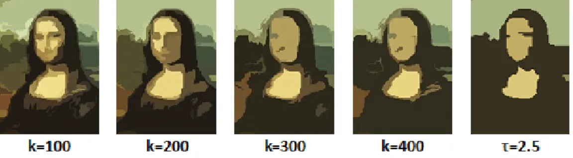
Figure 5.3: Effect of the choice ofkon the granularity in the MST segmentation algorithm output. (a)-(d) MST results for various values of k, showing the difficulty of selecting the proper value. (e) Our algorithm for τ = 2.5, which is the same value used for all images, despite scene content and image size.
5.2
Analysis of optimal segmentation
Another drawback of the minimum spanning tree algorithm is that the granularity of seg-mentation depends on the value ofk. This parameter is often chosen arbitrarily and thus there is no control over the granularity of segmentation. This fact is clearly illustrated in Figure 5.3. In our algorithm, since Mahalanobis distance between Gaussian distributions is used to merge regions, we
Figure 5.4: Our algorithm- different granularities of segmentation for a) Monalisa b) Man
hypothesize that a distance threshold of 2−2.5 would give us optimal results. This represents a good cutoff while comparing distributions because 2−2.5 Mahalanobis distance units corresponds to 2σ−2.5σin terms of Euclidean distance.
Figure 5.4 shows the segmentation obtained for different values of distance thresholdτ. We can observe from Figure 5.5 that the number of segments decreases asτincreases. However, when the
τ reaches 2−2.5, the curve flattens. In other words, the number of components become relatively stable to the changes in threshold. Such a segmentation represents “stable” regions because the regions are well formed and are not sensitive to parameter changes.
5.3
Results on the BSDS dataset
The algorithm was tested exhaustively on a subset of the Berkeley segmentation database [20]. This database contains 300RGBimages of size 481x321 pixels that are randomly chosen from the Corel database. These images are manually segmented by humans in a natural way. According to [20], the following instructions were given to the human subjects who segmented the image: “
Divide each image into pieces, where each piece represents a distinguished thing in the image. It is important that all of the pieces have approximately equal importance. The number of things in each
Figure 5.5: Graph showing the relationship between threshold and number of components for Mon-alisa (TOP) and Man (BOTTOM)
image is up to you. Something between 2 and 20 should be reasonable for any of our images.. ” We ran the MST algorithm (authors’ implementation) and our algorithm using the Berkeley
segmentation dataset [20]. The results are shown in Figures 5.6- 5.13. As can be seen, our results are noticeably improved in a wide variety of scenarios due to the modeling of each region with a Gaussian in RGB space, with no sacrifice in computational efficiency. It can be noticed that for most images, our algorithm produces results that are more closer to “correct” segmentation. Furthermore, our results are much “sharper” than the MST algorithm.
To justify the above claim, let us analyze Figure 5.6 in detail. MST algorithm fails to capture the person on the rock (second row), face of the man kneeling down (third row) and merges parts the bison’s body with the background (fourth row). All these problems are overcome by our algorithm . Furthermore, the airplane (first row) and cow (last row) results are much sharper in our algorithm.
Chapter 6
Conclusions and Discussion
We have proposed a novel segmentation algorithm that improves upon the two primary drawbacks of the MST based segmentation. Firstly, we replace the MST criterion for merging regions with bidirectional Mahalanobis distance, assuming that regions are modelled as Gaussian distrubutions in RGB space. Secondly, due to the use of Gaussians, we demonstrate that this choice of Gaussian distribution leads to a natural intuitive parameter for achieving good segmentation for a wide variety of images. All these results have been obtained without sacrificing the computational efficiency. We have validated our algorithm by testing on a wide variety of synthetic as well as real images. The performance of our algorithm is clearly superior to MST algorithm in most cases.
6.1
Future work
Following are some of the tasks that we plan to undertake in the near future to improve the results of this thesis:
1. Explore data structures that can possibly used to implement the segmentation algorithm such that updating the weights of edges and re-sorting can be performed efficiently.
2. Run the segmentation algorithm on the new Berkeley dataset (BSDS500) and evaluate its performance. Additionally, benchmark the different versions of the algorithm mathematically.
4. Preprocess the images of the dataset to make them less invariant to light. Homomorphic filtering would be one option to consider to improve our segmentation results.
Bibliography
[1] Pablo Arbelaez, Michael Maire, Charless Fowlkes, and Jitendra Malik. Contour detection and hierarchical image segmentation.IEEE Trans. Pattern Anal. Mach. Intell., 33(5):898–916, May 2011.
[2] Stanley T. Birchfield and Sriram Rangarajan. Spatiograms versus histograms for region-based tracking. InProceedings of Computer Vision and Pattern Recognition (CVPR’05) - Volume 2, CVPR ’05.
[3] Rub´en C´ardenes, Rodrigo de Luis-Garc´ıa, and Meritxell Bach-Cuadra. A multidimensional segmentation evaluation for medical image data. Comput. Methods Prog. Biomed., 96(2):108– 124, November 2009.
[4] Yizong Cheng. Mean shift, mode seeking, and clustering. IEEE Trans. Pattern Anal. Mach. Intell., 17(8):790–799, August 1995.
[5] F. R. K. Chung. Spectral Graph Theory. American Mathematical Society, 1997.
[6] Dorin Comaniciu and Peter Meer. Mean shift: A robust approach toward feature space analysis.
IEEE Trans. Pattern Anal. Mach. Intell., 24(5):603–619, May 2002.
[7] J´erˆome Da-Rugna, Ga¨el Chareyron, and Hubert Konik. About segmentation step in content-based image retrieval systems. InWorld Congress on Engineering and Computer Science, pages 550–554. IAENG, 2011.
[8] Guillaume Damiand and Patrick Resch. Split-and-merge algorithms defined on topological maps for 3d image segmentation. Graph. Models, 65(1-3):149–167, January 2003.
[9] Pedro F. Felzenszwalb and Daniel P. Huttenlocher. Efficient graph-based image segmentation.
Int. J. Comput. Vision, 59(2):167–181, September 2004.
[10] David A. Forsyth and Jean Ponce. Computer Vision: A Modern Approach. Prentice Hall Professional Technical Reference, 2002.
[11] Charless Fowlkes, Serge Belongie, Fan Chung, and Jitendra Malik. Spectral grouping using the nystrm method. IEEE Trans. Pattern Anal. Mach. Intell.
[12] C.L. Glisson, H.O. Altamar, S.D. Herrell, P. Clark, and R.L. Galloway. Comparison and assess-ment of semi-automatic image segassess-mentation in computed tomography scans for image-guided kidney surgery. Med Phys, 38(11):6265–74, 2011.
[13] Murad Al Haj, Andrew D. Bagdanov, Jordi Gonz`alez, and Xavier F. Roca. Robust and effi-cient multipose face detection using skin color segmentation. InProceedings of the 4th Iberian Conference on Pattern Recognition and Image Analysis, pages 152–159, 2009.
[14] Xiaofu He and Pengfei Shi. A new segmentation approach for iris recognition based on hand-held capture device. Pattern Recogn., 40(4):1326–1333, April 2007.
[15] Adam Hoover and Li Yu. Segmentation methods through the stability of region count in the scale space. InProceedings of International Conference on Image Processing, Computer Vision and Pattern Recognition, pages 467–473, 2006.
[16] Steven L. Horowitz and Theodosios Pavlidis. Picture segmentation by a tree traversal algorithm.
J. ACM, 23(2):368–388, April 1976.
[17] Piotr Indyk and Rajeev Motwani. Approximate nearest neighbors: towards removing the curse of dimensionality. InProceedings of the Thirtieth Annual ACM Symposium on Theory of Com-puting, pages 604–613, New York, NY, USA, 1998.
[18] J. B. Kruskal. On the Shortest Spanning Subtree of a Graph and the Traveling Salesman Problem. InProceedings of the American Mathematical Society, 7, 1956.
[19] Jitendra Malik, Serge Belongie, Thomas Leung, and Jianbo Shi. Contour and texture analysis for image segmentation. Int. J. Comput. Vision, 43(1):7–27, June 2001.
[20] D. Martin, C. Fowlkes, D. Tal, and J. Malik. A database of human segmented natural images and its application to evaluating segmentation algorithms and measuring ecological statistics. InProc. 8th Int’l Conf. Computer Vision, volume 2, pages 416–423, July 2001.
[21] Ines Njeh, Ismail Ben Ayed, and Ahmed Ben Hamida. A distribution-matching approach to mri brain tumor segmentation. InISBI, pages 1707–1710, 2012.
[22] Jorge N´u˜nez and Jorge Llacer. Astronomical image segmentation by self-organizing neural networks and wavelets. Neural Netw., 16(3-4):411–417, April 2003.
[23] Caroline Pantofaru. Studies in Using Image Segmentation to Improve Object Recognition. PhD thesis, Robotics Institute, Carnegie Mellon University, Pittsburgh, PA, May 2008.
[24] Dzung L. Pham, Chenyang Xu, and Jerry L. Prince. Current methods in medical image seg-mentation1. Annual Review of Biomedical Engineering, 2(1):315–337, 2000. PMID: 11701515. [25] R. C. Prim. Shortest connection networks and some generalizations.The Bell Systems Technical
Journal, 36(6):1389–1401, 1957.
[26] Jianbo Shi and J. Malik. Normalized cuts and image segmentation. Pattern Analysis and Machine Intelligence, IEEE Transactions on, 22(8):888 –905, aug 2000.
[27] M. Sonka, V. Hlavac, and R. Boyle.Image Processing, Analysis, and Machine Vision. Chapman & Hall, 2 edition, 1998.
[28] Michael Spann and Roland Wilson. A quad-tree approach to image segmentation which com-bines statistical and spatial information. Pattern Recognition, 18(3-4):257–269, 1985.
[29] David A. Tolliver and Gary L. Miller. Graph partitioning by spectral rounding: Applications in image segmentation and clustering. InComputer Vision and Pattern Recognition, CVPR ’06. [30] R. Unnikrishnan, C. Pantofaru, and M. Hebert. A measure for objective evaluation of image
segmentation algorithms. InComputer Vision and Pattern Recognition (CVPR’05) - Workshops - Volume 03, 2005.
[32] Li Yu. On the stability of region count in parameter space of image analysis methods. PhD thesis, Clemson University, Clemson, 2007.
[33] Yu Zhao, Zhiqiang Gao, and Baoxiu Mi. Fast image segmentation based on k-means algorithm. In Proceedings of the 4th International Conference on Internet Multimedia Computing and Service, ICIMCS ’12, pages 166–169, 2012.
![Figure 1.1: Example of image segmentation. a) Original image b) Segmented image [20]](https://thumb-us.123doks.com/thumbv2/123dok_us/86860.2509898/11.918.135.779.128.588/figure-example-image-segmentation-original-image-segmented-image.webp)

![Figure 5.6: BSDS300 Segmentation Results (Mean Colors)- I[20]](https://thumb-us.123doks.com/thumbv2/123dok_us/86860.2509898/41.918.146.775.167.956/figure-bsds-segmentation-results-mean-colors-i.webp)
![Figure 5.7: BSDS300 Segmentation Results (Contours)- I [20]](https://thumb-us.123doks.com/thumbv2/123dok_us/86860.2509898/42.918.136.774.160.979/figure-bsds-segmentation-results-contours-i.webp)
![Figure 5.8: BSDS300 Segmentation Results (Mean Colors)- II[20]](https://thumb-us.123doks.com/thumbv2/123dok_us/86860.2509898/43.918.146.762.144.999/figure-bsds-segmentation-results-mean-colors-ii.webp)
