Birkeland, John Olav (2009)
The potential of LIDAR as an antisubmarine
warfare sensor.
MPhil(R) thesis.
http://theses.gla.ac.uk/1252/
Copyright and moral rights for this thesis are retained by the author
A copy can be downloaded for personal non-commercial research or
study, without prior permission or charge
This thesis cannot be reproduced or quoted extensively from without first
obtaining permission in writing from the Author
The content must not be changed in any way or sold commercially in any
format or medium without the formal permission of the Author
When referring to this work, full bibliographic details including the
author, title, awarding institution and date of the thesis must be given
The potential of LIDAR as an aerial
antisubmarine warfare sensor
John Olav Birkeland
M.Phil – Research Faculty of Arts University of Glasgow
Acknowledgements
I would like to thank my supervisors in Glasgow, Dr. Phillips O’Brien and Dr. Nigel Barltrop, for valuable discussions and important guidance in the writing process. Also, Professor Jens Hjelmstad at NTNU in Trondheim has given important backup in pointing to alternative measures of submarines search, and has functioned as a safety net for the final product. I would like to thank my colleague and friend Major Gjert Lage Dyndal, now the dean of the Royal Norwegian Air Force Academy, for helping me into this research program and
recommending me for the LIDAR project that started in 2007. Your efforts and enthusiasm as a military academic stand unparalleled.
Without the support and understanding of by commanding officers this project would not have been possible. I would like to thank Brigadier General Ole Asak as the commander of the former Joint Air Operations Center at the National Joint Headquarters in Stavanger, and my closest commanding officers Lieutenant Colonels Tore Svendsen and Odd Harald Jenssen for giving me the flexibility to write in parallel to my work at the headquarters. Also,
Lieutenant Colonel Steinar Halvorsen at the Inspectorate of Air Operations provided the time and resources the final months of the writing process.
Last, but most importantly, I would like to thank Ingvild for putting up with my ambitious agenda the past year. Always encouraging and supporting, I am looking forward to new challenges together with you of whatever nature.
Oslo, November 2009 John O. Birkeland
Abstract
Traditionally, antisubmarine warfare (ASW) has been dominated by acoustic sensors, active and passive. Ending the Cold War, the ASW forces have refocused towards a theatre of war in the littorals, and the traditional acoustic sensors do not perform very well in such an
environment. The sensors are working much closer to the surface, and there is a lot more surface traffic to disturb the acoustic environment. Environmental and topographic factors also play a major role. Removing or significantly reducing the acoustic capability, one forces the ASW forces to look to other technologies and sensors to compliment or replace the acoustic ones. This is where the interest of LIDAR as an aerial ASW sensor comes into play.
The aim of this thesis is to evaluate “the potential for using LIDAR technology for aerial ASW
on Norwegian ASW platforms”. In addition to this main research question, the history of LIDAR has been researched, in order to find historical and existing LIDAR projects for ASW purposes.
Antisubmarine warfare is a complicated business, but speed of reaction, flexibility to change operating areas quickly and efficiently, and the ability to deploy sophisticated buoys are all in the advantage to the aerial ASW platform. But as the submarines get quieter and quieter, new means of detection must be found to cover the complicated upper layers of the water column.
The signal components of LIDAR and the increasing processing capability have made LIDAR technology somewhat mature, but limitations such as scattering and attenuation of light in water are severely hampering.
After a decline in ASW focus after the Cold War, the Western world is finding itself in a littoral submarine threat scenario, and do not have the sensors to sufficiently meet this threat. Several LIDAR programs have been initiated and carried through, but most have been directed towards finding and neutralizing mines. Lately, a new interest of applying LIDAR-technology in the search for submarines has risen. But LIDAR itself does not seem to be able to cover the upper layers of the water column consistently enough, and other technologies might be able to compliment LIDAR in a multi-sensor solution. Synthetic Aperture Radar (SAR) and Hyperspectral Imagery seem to be the most applicable of these. A
recommendation is given to military commanders to pursue a multi-sensor pod for several areas of use by Maritime Patrol Aircraft and military helicopters.
Table of contents
Acknowledgement….……… 2 Abstract………. 3 List of illustrations……….……… 4 1 Introduction……….. 8 1.1 Background………. 8 1.2 What is LIDAR?... 9 1.3 Statement of problem……….. 9 1.4 Limitations……….. 101.5 Methodology and sources……… 11
1.6 Disposition……… 12
Part I – Basis for discussion 2 Airborne ASW – An introduction……… 13
2.1 Background……….. 13
2.2 Acoustic sensors……… 14
2.2.1 Oceanography basics………. 14
2.2.2 Sonobuoys………. 15
2.2.3 The acoustic challenge……….. 18
2.2.4 The littoral challenge………. 19
2.2.5 Multistatic systems……… 24
2.3 Non-acoustic sensors……… 26
2.3.1 Radar……….. 26
2.3.2 Electronic Support Measures (ESM)………. 27
2.3.3 Magnetic Anomaly Detection (MAD)……… 28
2.3.4 Electro-optic/Infrared Cameras (EO/IR)……… 29
2.4 Summary……… … 30
3 LIDAR technology explained………….……… 31
3.1 Background……… 31
3.2 LIDAR hardware……… 33
3.2.1 Laser light……… 33
3.3 LIDAR software – Processing the returns……… 39
3.3.1 Wavelength……… 39
3.3.2 Finding the water surface……….. 41
3.4 Operational systems………. 43
3.4.1 The SHOALS system – a hydrographical example……….. 43
3.4.2 Amethyst – a Russian example………. 46
3.4.3 ATD-111 and April Showers – an American example………. 47
3.5 Performance………. 48
3.5.1 Operating environment and performance……….. 48
3.5.2 Limitations………. 49
3.6 Summary……… 50
Part II – Historical development 4 Antisubmarine Warfare – A shift in focus……… 52
4.1 Background……… 52
4.2 Changes in political focus……….. 54
4.2.1 The decline in ASW focus……….. 54
4.2.2 Refocusing on ASW……… 57
4.3 Changes in doctrine and tactics………..….... 60
4.4 A geographical change……….. ... 62
4.5 Summary………. 63
5 LIDAR – Historical development……….. 65
5.1 Background………...……. 65
5.2 Open and civilian research………..……. 68
5.3 Black programs and military development……… 71
5.4 Summary……… 79
Part III – Operational discussion 6 The need for LIDAR as an ASW sensor………...…… 80
6.2 A littoral ASW sensor……… 81
6.2.1 Current use of LIDAR………... 81
6.2.2 LIDAR tactics – the littoral challenge……….. 83
6.2.3 Pros and cons - summarized……….. 84
6.3 Alternative means of detection……… 86
6.3.1 Detection of submarine-induced bioluminescence……….. 86
6.3.2 Submarine-generated turbulent wakes and internal waves………... 87
6.3.3 Hyperspectral imagery……….. 88
6.4 A multi-sensor ASW-pod?... 90
6.4.1 Combining three technologies……….. 91
6.4.2 Multi-sensor tactics……….. 92
6.4.3 Flexible use……….. 93
6.4.4 Affordability………. 94
6.5 Summary……….. 94
7 Conclusion and recommendation………. 96
7.1 Conclusion – What has been done until now?... 96
7.2 Recommendation – The way forward……… 97
Abbreviations……….. 98
List of illustrations
Figure 2.1 Layers in the water column……… 14
Figure 2.2 Acoustic sensors………... 16
Figure 2.3 The acoustic challenge……… 18
Figure 2.4 Open water vs. littoral search………... 21
Figure 2.5 Deep vs. shallow water search………... … 22
Figure 2.6 Acoustic tactics………. 23
Figure 2.7 Monostatic and bistatic systems………... 24
Figure 2.8 Multistatic systems………... 24
Figure 2.9 Radar search……….……….. 26
Figure 2.10 ESM search………... 27
Figure 2.11 MAD search………. 28
Figure 2.12 EO/IR search……… … 29
Figure 3.1 Airborne vs. surface based surveys……… 32
Figure 3.2 Laser in principle……… 33
Figure 3.3 Basic LIDAR……… 34
Figure 3.4 Advanced LIDAR………. 34
Figure 3.5 Spreading of laser light………. 35
Figure 3.6 Inertial Measurement Units……….. 37
Figure 3.7 Scattering of the light beam……….. 40
Figure 3.8 SHOALS performance………. 43
Figure 3.9 Surface vs. bottom return………. 44
Figure 3.10 Shallow water waveform……… 44
Figure 3.11 Deep water waveform………. 45
Figure 3.12 Waveform showing return close to seabed………. 45
Figure 3.13 Waveform showing mid-water column return………... 45
Figure 5.1 The Learning S-curve………... 72
Figure 5.2 U.S. military LIDAR development……….. 77
Figure 6.1 Multi-frequency radar matching the surface roughness……… 88
Figure 6.2 Water optics……….. 89
Figure 6.3 Multi-sensor ASW-pod……… 91
1 – Introduction
1.1 Background
The background for this thesis lies in a constant effort to improve as an anti-submarine warfare (ASW) force. The art of hunting a submarine is not easily taught, and not easily acquired. The wish to control one’s adversary’s submarines is as old as the submarine force itself. From the early submersible vessels of the late 1800s, to the superbly advances nuclear attack submarines of today, the silent service has always posed a significant threat, in war as in peace time.
ASW has always demanded both state-of-the-art sensors, as well as highly trained operators. The lack of one of these has called for a raised level of the other. Technologywise, the submarine force and the ASW forces have always been in a race for constant
improvement. Better sensors have called for quieter submarines, and vice versa. And traditionally, ASW has been dominated by acoustic sensors, active or passive. The passive sensors are deployed in the water to listen for sounds emitted by the submarine. Active sensors will transmit a sound themselves, and then listen out for the echo returned by the target submarine. The use of the respective sensor is obviously closely linked to the tactics being pursued by the ASW platform or force.
In World War II the German “Wolfpacks” posed a tremendous threat to allied shipping, it being convoys of merchant ships as well as transiting warships. But they hardly ever operated close to the shore, in the littoral waters. Their area of domination was the open ocean, the so-called blue water regions of the Atlantic and the Pacific. The submarines would hide under the surface, shadow a convoy, and attack at the right moment. Obviously, the known sea-lines of communication (SLOCs) were the most likely area to find an enemy submarine, but in principle, the entire ocean was a friendly forces’ search area. Even more so than with the submarines of the Second World War, the gigantic submarines of the Cold War carrying ballistic missiles had the open ocean as their playing field. As an absolutely essential part of the mutually assured destruction (MAD) strategy, the submarines carrying ballistic missiles (SSBNs) would hide in the deep, ready to fire their deadly load from a hidden position, and thus assuring the ability for a second strike.
forces, that the traditional passive acoustic sensors do not perform very well in the littorals. One is working much closer to the surface, and there is a lot more surface traffic to disturb the acoustic environment. Environmental and topographic factors also play a major role.
Removing or significantly reducing the acoustic passive capability, one forces the ASW forces to look to other technologies and sensors to compliment or replace the acoustic ones. This is where the interest of LIDAR as an aerial ASW sensor comes into play.
1.2 What is LIDAR?
“LIDAR” is an acronym for “LIght Detection And Ranging”, and the technology is based on laser equipment and additional analyzing processors. Aerial LIDARs are carried by airplanes and helicopters, and are flown over the surface, be it land or ocean, that is to be analyzed. The laser emits a narrow beam of light, and the receivers send the returned signals to electronic processors that in turn analyze the different wavelengths of light. The returned signals will provide the basis for telling the operator details about ground elevation, ground conditions and structure, ocean characteristics, ocean depths and other desired surveying information. Currently the civilian world can offer LIDAR systems that perform levee profiling, dredge deposit evaluation, corridor and floodplain mapping, fish stock surveys and of course oceanographic and bathytermal surveys and mapping. Different military agencies have developed LIDARs for use in mine search, originally based on a desire to find submerged submarines by the use of lasers. Other military applications in the future can be a support to the compilation of a Rapid Environmental Picture (REP) before conducting amphibious operations.
1.3 Statement of problem
This project originally rose as a question posed to the Concept Development and Evaluation (CD & E) group at the National Joint Headquarters (NJHQ) in Norway in the fall of 2006. The discussion started between officers with a background from the Norwegian 333 squadron at Andøya in Northern Norway. The 333 squadron has a proud history of conducting aerial ASW with several different ASW aircraft along the years, and has since the late 1960s flown the P-3 Orion, with many heavy upgrades in airframe and sensor portfolio. Reading articles on researching fish stocks in the water with laser beams mounted on aircraft, one started to discuss the ability to use the same type of equipment to search for submerged submarines. But
between different families of schools of fish in the water, and known ASW-platforms do not possess a similar capability? Could this technology be placed on a P-3? And how deep will a laser beam be able to search for a submarine? The CD & E group authorized the project the following spring, with the aim of having a master thesis evaluate the following:
“What is the potential for using LIDAR technology for aerial ASW on Norwegian ASW platforms?”
In addition to this main research question, some underlying questions will be sought answered. What is the history of LIDAR research, that is, what projects have been pursued earlier? Has the question of LIDAR potential for ASW been asked earlier, and if so, what is the reason for current ASW platforms not possessing this capacity today?
1.4 Limitations
The empirical material gathered in the research for this thesis is very much based on technological and operational reports coming out of the U.S.A. This can be attributed to several factors. The U.S. has a long tradition of publicizing technological research to a greater extent than is to some degree usual in Norway and Europe. The results of civilian testing of LIDAR are no exception, and many reports have been readily available on the internet and in libraries. Based on an extensive research and as will become clear later in the dissertation, by far the most activity in the field of LIDAR research has been based out of the U.S.A. The fact that we do not have any operational aerial antisubmarine warfare platforms flying with functioning LIDAR-equipment meant for hunting submarines, and that the discussion of placing such equipment on P-3 Orions first rose several years into the 2000s in the U.S., supports the idea of looking to the U.S. first in order to see the current state of the technology.
In addition, from a Norwegian standpoint, it is always important to stay in touch with the direction and development of American warfighting capabilities, as the U.S.A. is by far the closest ally when it comes to military acquisition. Knowing the thoughts of the American politicians and the evaluation of different technologies will provide the basis for the need to perform similar processes of development and evaluation of our own. If the largest military in the world does not consider the technology cost-efficient or affordable enough to pursue,
good chance of other countries finding similar ways to put the technology to use, and maybe even additional ones.
Norwegian ASW assets work closely with other allies as well, such as the U.K., Germany and France, but open sources do not reveal any information on LIDAR programs presently being pursued in these countries. Needless to say, this does not preclude any classified programs from currently taking place.
1.5 Methodology and sources
This thesis is mainly based on literature research. For the technological details, many research reports have been studied, mostly written by the researchers themselves. Not being a
technology graduate, this has at times been challenging. But it has been important for the final product, that this thesis is not a technological report, but an operational evaluation of the potential technology as a whole. The technological details have been tried reduced to a minimum, however some have been necessary to include, especially in an effort to build up some credibility in the technology chapter.
Three technology reports have been tried declassified from U.S. CONFIDENTIAL, of which only one has successfully gone through the Washington bureaucracy over the past 2 years. Hopefully, the thesis provides a credible discussion mainly based on open sources.
Several sections have been written based on the author’s personal knowledge and experience as an officer in the Royal Norwegian Air Force and a Tactical Coordinator
(TACCO) on P-3 Orions. Where needed, information has been sought from open sources. But due to the highly classified nature of the technical and tactical details of ASW, a more
detailed discussion than the one provided here will border on privileged information. This has of course led to some restrictions, but hopefully the provided information will suffice.
There is apparently no open discussion going on as of now regarding the potential of LIDAR as an ASW sensor, other than the U.S. Navy’s proposal to expand their existing mine countermeasure-program to include LIDAR on the P-3 Orion (details will follow). Not much information on this is available, and naval theorists have not been very explicit on this matter. Both Norman Friedman and Geoffrey Till have pointed to the challenge of conducting
efficient ASW in the littorals, but have not gone further into details other than proposing exploring searching by non-acoustic means such as lasers. Internet forums and submarine-authors have discussed the potential of a hypothetic sensor that is able to “see through the
capabilities in the civilian world, and is considered efficient enough for the U.S. Navy to carry on their mine countermeasure-program with LIDAR installed on helicopters. The potential as an ASW sensor, however, is not heavily debated apparently in any open forum. One of the challenges of this thesis have been the effort of digging into a discussion that is not really there, and thus perhaps initiate one that can be of use for the ASW-community.
1.6 Disposition
This introduction has had the goal of providing the reader with enough motivation to read the following chapters leading up to a humble recommendation. The dissertation as a whole consists of 3 parts, each consisting of two chapters.
Part I provides a background for the discussion, with two chapters with basic information. Chapter 2 gives an introduction to aerial antisubmarine warfare in order to provide an insight into the sensor portfolio usually present onboard aerial ASW platforms of today. Chapter 3 explains the basics of LIDAR technology, from the basic components of lasers to the challenge of interpreting the frequencies on light being returned form the water (and hopefully the target).
Part II lays out the historical development of LIDAR as a technology, and the changing focus on ASW. Chapter 4 discusses the different changes in tactics, doctrine and political focus that we have seen from the mid-1980s up until today. Chapter 5 gives a detailed overview of the development of LIDAR technology, both civilian and military. The civilian and military-civilian programs have mainly focused on areas of interest for both communities, mostly being hydrography and the mapping of shallow, coastal waters. This information is readily available in books, reports and on the internet. The military programs have been either entirely “black”, or hidden from the public, or known to the public through congressional budget discussions. This chapter gives an idea of where the technology-development is today.
Part III is the evaluation of LIDAR for ASW, and the presentation of alternative technologies to possibly compliment LIDAR as a sensor. Consisting of two chapters, chapter 6 will first discuss LIDAR for ASW in isolation. Then alternative methods of non-acoustic detection will be discussed, calling for other technologies in addition to LIDAR. Chapter 7 is a short and humble conclusion and a recommendation for military commanders when it comes
2 – Airborne ASW – An introduction
2.1 Background
The classical distinction within submarine technology is between the two main types of propulsion; diesel-electric and nuclear. Obviously, the first submarines were diesel-electric, but as the nuclear powers developed smaller and more efficient reactors, the desire to move faster and longer with bigger submarines without replenishment over an extended period of time came to the scene. Most submarines carrying ballistic missiles (SSBN) are nuclear powered, and are able to operate almost anywhere in the world for months at a time. Attack submarines can be nuclear (SSN) or diesel-electric (SSK) – the SSKs usually do not operate very far from the shore as they need to replenish diesel, a need the SSNs don’t have. The SSKs are almost without exception smaller than their nuclear sister boats, and are often likely to operate in a near-shore environment due to their size and maneuverability. In addition, some new submarines have Air Independent Propulsion (AIP), and are powered by fuel-cells that are charged without air. These submarines are also incredibly silent, and can
operationally be referred to as something of a hybrid between nuclear and diesel-electric propulsion. They are, however, as quiet as the SSKs.
In World War II, airborne radar was the primary anti-submarine warfare (ASW) sensor. Boats were usually diesel driven and consequently had to surface to recharge batteries, and many submarines chose to transit on the surface where possible to achieve greater speeds (Mason 1987:103). As the nuclear technology matured, some oceangoing vessels started to be designed with nuclear propulsion. When the nuclear submarines were sent to sea, new and improved ways of detecting the submerged vessels were needed, and other technologies than radar were developed and refined. Airborne ASW is usually performed by either long-range land-based aircraft or shorter-range ship-borne helicopters. The aircraft have a long endurance of nine hours or more, with an extensive sensor capacity and a relatively fast transiting speed, at least compared to the helicopters and surface vessels. The aircraft, usually referred to as Maritime Patrol Aircraft (MPA), are fitted with sensors such as sonobuoys, radar, magnetic anomaly detection (MAD), electronic support measures (ESM), and electro-optic and infrared cameras (EO/IR), apart from the obvious visual detections made by the crew themselves. The following will give a brief introduction to the different sensors.
2.2 Acoustic sensors
2.2.1 Oceanography basicsExcept under polar icecaps, where the temperature is constant regardless of depth, the sea has a layered architecture that determines the speed of sound. Sound velocities vary with water temperature, pressure and salinity. Salinity plays a role, but the biggest factors are
temperature and pressure. Cooler temperatures lower speed while higher pressures increase it. Sound in water will always seek towards the area where the speed is the lowest, so initially the sound will seek towards the cool abyss, before the pressure becomes so high that the sound is bent upwards again towards the point of minimum velocity (see figure 2.1).
Figure 2.1
Layers in the water column
The surface layer gains and loses heat in response to influences such as sun-light and changes in season. This means that parts of the layer can be warmer than the other, leading to the common phenomenon of temperature increase with water depth. The layer can go as deep as 60 – 90 meters (> 200 feet) (Hassig 1992:67).
The next layer is called the thermocline. In this layer the temperature drops steadily
Surface layer Down to 60-90m Main Thermocline Down to 600-700m Isothermal layer Down to bottom Point of minimum velocity
reaches a minimum, and the water temperature stabilizes at around 4 degrees Celsius (around 39 degrees Fahrenheit).
From the thermocline to the bottom is the isothermal layer with a constant temperature. Here, the sound velocity increases as pressure increases with depth.
If a submarine is in the surface layer, much of the noise from the submarine will be confined there by reflection and upwards refraction, contributing to the loudness of the environment which is already there because of surface traffic, sea life and other
environmental factors. The surface layer is, in short, a very complicated and noisy environment for acoustic sensors.
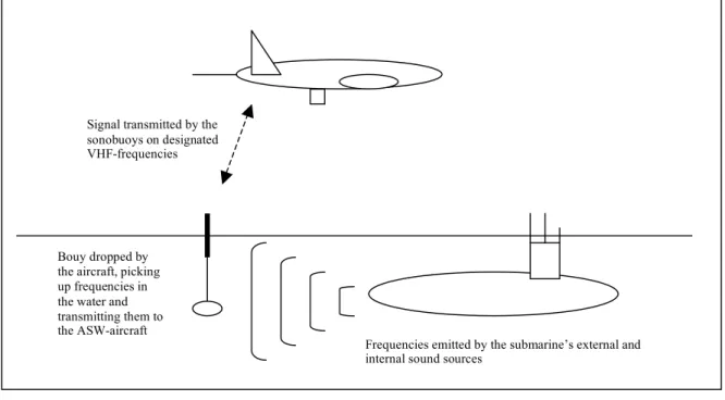
2.2.2 Sonobuoys
Probably the most distinct feature of airborne ASW is the dropping of sonobuoys in order to search for frequencies emitted by the submarine. The submarines are mechanically driven, and emit sounds from their machinery in almost all circumstances. The sounds come from external units such as the propeller(s) and hydroplanes, or they come from internal equipment such as electrical generators. The aircraft drops disposable sonobuoys into the water, which is really a floating microphone, listening for sounds from the ocean. After dropping the buoys, several factors complicate matters.
Oceans tend to be noisy, regardless of geographical position. Sea-life, shipping-traffic, surface winds, and seismic activity are examples of what is referred to as ambient noise. One of the challenges for the analysts onboard the aircraft is to distinguish between this ambient noise and the frequencies emitted by the submarine. Of course, this ambient noise is also known to the submarine commander, who in turn will try to “hide” the sounds of the sub among these ambient frequencies.
As mentioned in the previous section, oceanographic factors such as salinity, temperature and pressure have an impact on how sounds move through the water. These factors change daily, as well as in concert with the season. They also differ according to geographical factors such as proximity to lakes and fjords, in littoral waters as opposed to the open ocean, seasonal changes to temperatures and seasonal
Figure 2.2 Acoustic sensors
changes to currents and winds. And as explained, these oceanographic factors and their layers determine where and how the sounds from an emitter are distributed. One example of
submarine tactics is that if there is a clearly defined layer in the upper part of the water
column, which the sound waves are moving away from, the submarine will try to stay beneath the layer in order “steer away” the emitted sounds that can be recorded by sonobuoys placed on the surface. In turn, the sonobuoy operator will lower the hydrophone to get it underneath the layer in its search for submarine sound waves, in case he doesn’t find the submarine inside the layer. The submarine skipper is aware of this capacity, and may in turn move closer to the layer or even into the layer, in order to mask the submarine’s own noise behind the sounds that are close to the surface.
In addition to these challenges to the ASW-aircraft, the submarines are becoming quieter and quieter. Diesel-electric submarines are both very loud and very quiet. When the batteries are fully loaded, the only sounds being emitted are those of the mechanical, external parts and a little of the internal machinery such as the gearboxes. The electronic components have become almost undetectable. But when the batteries need to be charged, the submarine will be on the surface and running its diesel engine. The diesel-engines have become quieter by the years as well, but have distinctive engine sounds that spread very easily through the water.
Signal transmitted by the sonobuoys on designated VHF-frequencies
Frequencies emitted by the submarine’s external and internal sound sources
Bouy dropped by the aircraft, picking up frequencies in the water and transmitting them to the ASW-aircraft
likely to occur only during prolonged missions for the sub, as opposed to during the relatively short on-station period of the ASW-aircraft.
Placing small, mobile sensors in a volatile environment such as the ocean will always pose challenges. Most sonobuoys do not have any positioning equipment on them by themselves, and need to be located by the aircraft once dropped. The aircraft computer-system will note where the buoy was originally dropped, but after the drop the buoy will immediately start to drift. The drift is caused by factors such as wind, local currents, seasonal currents and sea-state. After some time in the water the buoys must be relocated, and the updated position must be entered into the aircraft computer. Some buoys have now been developed with GPS
embedded into the buoy itself, which makes them able to transmit their own position together with the sound-information they are gathering. This keeps the aircraft computer updated at all times as to where the different buoys are located, obviously helping a lot in the job of locating the sounds in the water. This solution, however, is quite expensive, as the buoys are
disposable and only used once.
Another challenge is the life-length of the sonobuoys, which is variable by the operator from 30 minutes to 8 hours. The life of a buoy can be set by the operators, and is usually set according to the tactical situation. When the aircraft is prosecuting a submarine the crew and their computer must keep track of the remaining life of the buoys, so that the submarine doesn’t get away due to buoys not functioning any more.
The accuracy of the sonobuoys is an important factor to the operators of the ASW-aircraft. As mentioned, distinguishing between sounds emitted by the submarine and other sounds in the water will always be a challenge, but once this distinction has been made it is necessary to pinpoint where the sounds are actually coming from. The delay made by the sound moving through water at a slower speed than for example light, gives the buoys the disadvantage of pointing towards where the submarine was several seconds ago. Working “in the past” like this can be difficult. The operators of the aircraft must always try to predict the movement of the sub as a continuation of the movements just made, or place the sensors to safeguard from turns and shift in depth performed by the submarine.
If a sonobuoy is only able to listen for submarine frequencies and other sounds in the water, it is usually referred to as a passive bouy. Bouys that transmit a sonar sound around it function almost as an underwater radar, which sends out an electronic signal in order to receive an echo of the emitted sound returned by the submarine. These buoys are referred to as active sonobuoys. With knowledge of the local water conditions, and the speed of sound
instantly calculated, thereby accelerating target localization (Mason 1987:104). The downside to this is that the submarine will be warned that it has been detected.
2.2.3 The acoustic challenge
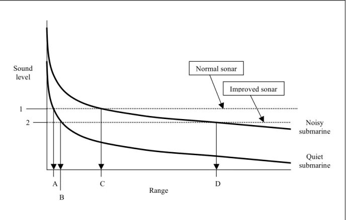
The acoustic challenge is illustrated through figure 2.3, where the sound of a submarine versus its range from a passive sonar is depicted. Both submarine curves show how the sound of the submarine radiates through the water.
Figure 2.3 The acoustic challenge
The sound diminishes with the square of the distance, which means that by doubling the distance you cut the sound by a factor of four. After reaching the bottom, the sound expands cylindrically as opposed to spherically, and therefore diminishes directly with distance rather than by its square.
Looking at the graph, the normal sonar will detect the noisy submarine at the range of point C, and an improved sonar will be able to detect the noisy submarine all the way out to point D. Now the quiet submarine starts much lower on the graph, and quickly drops to the
Sound level Range 1 2 A B C D Noisy submarine Quiet submarine Normal sonar Improved sonar
In plain terms, this means that more passive sonar equipment is needed in order to cover the same area acoustically than was the case before. Another thing to read out of the graph is that further improving the sonars will not do very much with the problem. The solution seems to be either converting to an active sonar or sonobuoy at an earlier point in the tactics deployed by the ASW forces, or using non-acoustic sensors in the search for the target. This refocusing on non-acoustic sensors, and the research being done to meet the acoustic challenge has been called one of the greatest technological challenges facing the Department of Defense (Congressional Hearing 1989:62).
2.2.4 The littoral challenge
Anyone who has been involved in the cat-and-mouse game that is an ASW-operation or exercise, will report that littoral waters and the archipelago is a navigational nightmare for the submarine and a oceanographic nightmare for the surface and airborne ASW-forces. The navigational factors playing against the sub have already been mentioned. The oceanographic factors working against the sensors deployed by the ASW-forces are small islands, sticks, floating devices and marine life on the surface confusing the radars. The same problem is working against the visual lookout by the crew. Looking for electronic emissions done by the submarine such as the sub emitting radar signals or radio communication is like searching for a needle in a haystack, with all the other electronic signals flying through the air from emitters on land. Acoustically, the traditional search method for looking for a submarine, the near-shore environment is immensely complex, with an increased amount of dense surface traffic (as opposed to the open seas), the shallow water providing more noise from sea life, and currents and weather factors creating an unpredictable path for the sound waves. Magnetically one is working with a shallower water column, having ship-wrecks and other items on the bottom providing false hits for the magnetic anomaly detector (MAD). In short, the littorals and the archipelago is incredibly complex and challenging for the ASW-forces to search for the submarine in, and can be very challenging for the submarine to navigate through.
But the new SSKs are tremendously efficient in littoral waters. Examples of efficient SSKs are the German produced Dolphin-class, the Russian produced Kilo-class and the Chinese produced and heavily Kilo-influenced Yuan-class. Being smaller than the nuclear boats, they can more easily operate in the littorals. Their stealth factor is increased by the fact that a ship’s sonar or an MPA’s passive buoys’ effectiveness is degraded in these waters.
bottom and thus send confusing signals back to the operator. The sound-search is also
disturbed by the general clutter of sounds in the littorals. More sea-life, more shipping traffic, more wrecks at the bottom and more general ambient noise interfere with the signals. Sounds are also refracted and reflected by the different layers in the water column that are more clearly distinguished from each other in coastal waters. This phenomenon is especially noticeable in areas where there is little storm activity, such as in the Persian Gulf, and thus little mixing of the cold and warm layers in the water. Strong currents and fresh-water run-off from rivers also create confused layers of salinity, which again degrade sonar effectiveness (Thornton 2007:112). Simply put, an SSK operating in the littorals can be very hard to find.
The characteristics of the littorals actually enhance the SSK’s offensive capabilities. It becomes hard for the surface ships to protect themselves, given that any incoming torpedoes fired from submarines will be difficult to pick up on sensors, again because of coastal clutter. The lack of maneuvering room close inshore will also hinder evasive tactics for the attacked unit. These factors lead up to a situation, where powerful navies are being dragged into littoral waters where they may have to face the asymmetric threat of better SSKs in an environment which enhances the SSKs capabilities while degrading those of their notionally more
powerful opponents
(Thornton 2007:113). The naval battles between Iran and the U.S. Navy in April of 1988 taught the hopelessly outclassed Iranian forces that large vessels are vulnerable to air and missile attacks, and led Iran into an official doctrine of asymmetric naval warfare
(Haghshenass 2006). They have consistently acquired and developed small, fast weapons platforms in the form of lightly armed small boats and missile-armed fast-attack craft, and midget and diesel-electric attack submarines. In 1999 Admiral Cebrowski, the head of the Naval War College and the Naval Warfare Development Command directed broader littoral aspects to be explored in the annual Global War Game held at the Naval War College (Work 2004:48). Naval exercises and war games have consistently addressed near shore issues since the turn of the century, in order to try to meet these challenges.
A Norwegian submarine commander discussed littoral challenges in 1994, and looking at the (at the time) current state of ASW technology somewhat pessimistically exclaimed that “there is nothing yet to indicate that we are facing a technological breakthrough with regard to coastal or inshore ASW” (Till 1994:159). With the development of non-acoustic
A common tactic for submarines is to deliberately move into a position closer to the shore, in order to complicate the search for the ASW-forces.
Not only is the environment more intense and the sound-sources more dense, but the ASW-assets are forced to work physically more close to each other, which necessitates a strict coordination of deployment of sensors. This is much more easily coordinated further from the shore, where one is able to draw up lines for each asset’s search-box. In a fjord, or close to the archipelago, this becomes much more complicated as the entire area of interest may be the fjord itself or the inlet to one or several fjords. The complexity of integrating ASW forces in near-shore environments were shown through exercises as early in the mid- and late 1980s, and is still a challenge (Grove 1991:120).
The open water search in search box A (figure 2.4) might be the classic transit along sea-lines of communications (SLOCs) away from the shore, like in the case of transiting between continents, from an island country to a mainland continent and so on. This search environment will always be relevant, however, it has been toned down somewhat in the later years. Several submarine types have been specifically designed to track and target big aircraft carrier groups (Pike et al. 2000). Sailing from its homeland into a theatre of war, such groups
Figure 2.4 = surface traffic
= enemy submarine Search box A – Open water search
Water
Search box B – Littoral search
Water
Land
meet such an extensive force out at sea demands a significant amount of logistics, not to mention training and sophistication of equipment. Few nations are able to meet this challenge with their peacetime organization of their military forces.
The submarine in search box B (figure 2.4) must navigate through narrow straits and fjords, but can do so slowly and in established shipping lanes. A proficient submarine skipper will mask the noise being emitted by the vessel into the water behind merchant ships and fishing vessels. This will make it even harder for the ASW-forces to single out the enemy submarine from a friendly fisherman. The task usually being intelligence gathering, sabotage or letting on and off agents and special forces, the smaller submarines necessarily have to get close to the shore due to the nature of their mission. Instead of meeting their target out at sea, or patrolling the oceans waiting for the executive order to fire a missile, the small attack submarines are forced to approach enemy territory in order to accomplish their mission. In other words, many submarines are forced into a challenging environment to navigate through, however one that provides plenty of opportunity to hide and lurch their way towards their goal.
Both offensively and defensively, the dense environment of search box B (figure 2.4) is preferable to the submarine. Although a challenge to the navigator, the submarine is able to hide both behind physical hinders such as small islands, and oceanographic factors such as the noise from shipping and other activity.
Acoustically, the littoral environment is enhancing the submarine’s ability to operate
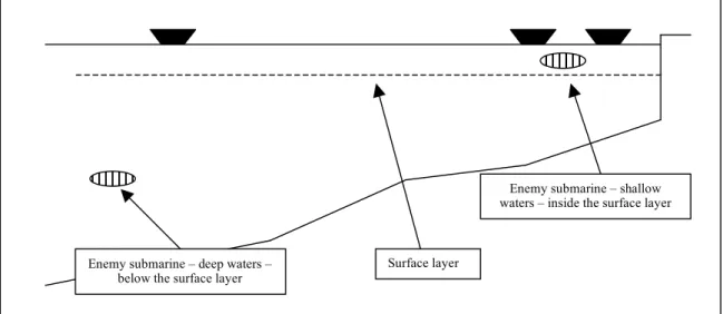
Enemy submarine – deep waters – below the surface layer
Enemy submarine – shallow waters – inside the surface layer
Surface layer
Figure 2.5 Deep vs. shallow search
nearby, and together with ambient noise the surroundings are often masking out the sounds from the submarine altogether. The submarine that is out to sea is operating deeper and is much more free to navigate with much less obstacles and surface traffic disturbing her
mission. However, operating below the surface layer lets the sonars of surface ships and MPA sonobuoys function optimally, and the traditional acoustic advantage of the ASW forces comes into play. This advantage is removed when the submarine is working close to the shore.
In figure 2.6 the two submarines are in two different acoustic situations, although they are geographically close to each other. Submarine A is inside the surface layer, close to the surface, moving in an environment where it is very noisy and difficult for the hydrophone dropped by the aircraft to operate efficiently. Some of the sounds emitted by submarine A escape the layer, but this is very little and is hard to pick up. Submarine B is below the layer, more free to maneuver but is also more likely to be detected by traditional acoustic sensors. The paths of the sounds being emitted by the submarines belong to an oceanographic discussion, but suffice it to say, most of the sound follows a direct path, and some of the sound is bent downwards towards the bottom with cooler, more saline water where the sound moves slower, before being bent upwards again because of the pressure, as was mentioned in section 2.2.1.
The challenge of the littorals lies in the fact that most of the submarines will work closer to the noisy upper sound layer, where traditional means of acoustic detection are less
Sonobuoy Surface Surface layer Hydrophone Sub B Sub A Sound paths Figure 2.6 Acoustic tactics
2.2.5 Multistatic systems
In order to meet this challenge acoustically, multistatic systems have been developed that will search for a submerged target under difficult acoustic conditions. Monostatic acoustic systems consist of one active buoy that sends out a sound, or a ping, which reflects off the target submarine and returns to the buoy. The system is very much like an underwater radar, and is usually just referred to as “active buoys”. Bistatic systems consist of two platforms, for example two ships or two separate buoys, where one platform is the active one and the other is the passive. Figure 6.1 shows monostatic and bistatic examples.
Figure 2.7
Monostatic and bistatic systems
But when using active sensors, it’s the use of multistatic systems that provides the real benefits. Low frequency multistatic systems have been under development for at least
= active buoy = passive buoy Monostatic – one
active buoy/platform
Bistatic – two platforms: one active and one passive
= Active buoy = Passive buoy
10 years, and have focused on the active parts of the system that can be deployed wherever the ASW forces need them. Multistatic systems have several passive platforms or buoys, and often more than one active pinger or explosive buoy. The system will note the timing of the transmitted pings or explosions, and then record the returns on all the passive sensors. This will give the computer the opportunity to triangulate the position of the enemy submarine.
There are operational multistatic sonar systems in use by MPAs, and several systems are under development. These are capable systems, but they have their limitations. The multistatic systems are active and very revealing when it comes to letting the enemy
submarine know about the presence of the ASW force. And the multistatic systems are not as efficient in littoral waters, due to the proximity to the bottom, the shore and the archipelago. These factors will provide many false and confusing returns. Also, fresh water, differences in temperature, turbulence and currents in the littorals will create layers in the water, which complicate all sorts of acoustic searches, no matter how efficient they are.
2.3 Non-acoustic sensors
2.3.1 RadarWith the technology constantly improving, the ASW radars of today have an impressive portfolio of features. They offer multiple-target tracking and a classification capability, giving the outlines of targets at long ranges. The radars are able to give a high detection and tracking performance despite high sea states. Several radars also have an Identification Friend or Foe (IFF) capability, as well as an air-to-air and a weather mode. ASW radars of today can be expected to detect large ships out to 150 nautical miles (nm) or more, vessels under 100 tons at 40 nm, surfaced submarines at 75 nm and snorting submarines at 20 nm (Laite 1991:51).
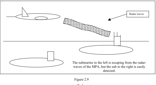
Figure 2.9 Radar
More accurate numbers presenting performance are classified, and are constantly improving. Newer radars have the ability to provide a visual reproduction of the radar profile of the target ship, called Inverse Synthetic Aperture Radar (ISAR). This is an important feature for a cost-efficient surveillance mission.
The proper way to use radar tactics is a science in itself. But regardless of operator efficiency, the sub can easily escape the MPA radar by staying submerged. The wavelength of radars does not penetrate water, making the operator only able to see what is on the surface.
The submarine to the left is escaping from the radar-waves of the MPA, but the sub to the right is easily
detected.
2.3.2 Electronic Support Measures (ESM)
The ESM-equipment gives the operator the ability to search for, locate and classify electronic transmissions made by the adversary. New systems have a wide radio frequency (RF)
bandwidth, and are able to search for a wide range of electronic transmissions. The classification is based on comparisons of the features of the intercepted signal with a
computer memory store of many of the transmissions likely to be heard. Military intelligence also provides frequencies and other electronic parameters for the operator to look for.
Although most navies are imposing severe restrictions to the electronic transmissions allowed to be made, some transmissions have to be made regardless. Examples include vital
communications, occasional sweeps of area-defence radars, and the concentrated aiming of live-fire-control radars (Laite 1991:52).
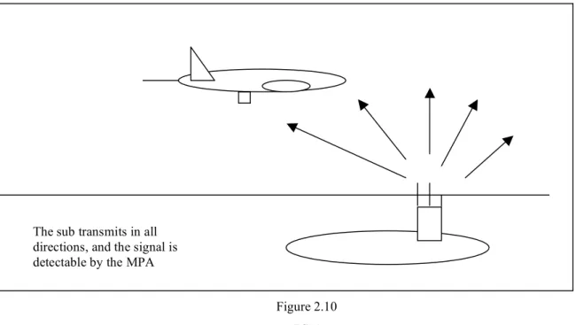
Figure 2.10 ESM
The downside to this sensor is the same as with radar, and has one in addition: First, the submarine has to be surfaced, or at least have to expose her radar mast. Second, the radar antenna has to be emitting. Simply put, the submarine is undetectable by the MPA ESM-equipment if it is submerged or has the radar turned off while on the surface.
The sub transmits in all directions, and the signal is detectable by the MPA
2.3.3 Magnetic Anomaly Detection (MAD)
Most MPAs have a boom-shaped tail which easily distinguish them from other types of aircraft. The equipment inside the boom consists of magnetic sensors, and is used to detect changes in the background magnetic induction that are associated with submarines. In other words, the sensors pick up disturbances in the earth’s magnetic field. The Earth’s magnetic field usually varies slowly over distance, but when a submarine is present the field changes rapidly and may de detected by a low flying aircraft carrying MAD equipment. Submarines contain a large amount of metal that becomes magnetized in the course of normal operations. Large metal objects will always disturb the magnetic field that is distributed between the North and South Pole, and in the case of ASW, the submarine functions as a large chunk of metal in the water. When the aircraft flies at a low altitude, this disturbance is noticeable, and will be recorded by the operator inside. The disturbance is not nearly significant enough to provide an efficient means of searching for the submarine, but it functions as a tool for confirming the presence of the submarine.
Figure 2.11 MAD
The immediate downside to this sensor is that one cannot use the MAD to perform a blind search for a submarine. It is, however, a valid and good complementary sensor. Also, it performs poorly when it comes to a littoral search, as the sensor will react far too easily on false targets, such as ship-wrecks and cables on the bottom.
The presence of the sub creates a disturbance in the earth’s magnetic field, detectable by the MPA’s MAD-boom
2.3.4 Electro-Optic/Infrared Cameras (EO/IR)
Cameras have always been important sensors for the MPAs in their gathering of intelligence of all sorts. Starting with handheld cameras almost as early as the first airplanes, moving on to cameras integrated with other sensors and built into the airframe itself today, they provide details for further analysis either in-flight or post landing. The new EO/IR cameras of today do not function very well as a search asset, but they give an extraordinary opportunity to zoom in on a prospective target from a distance and classify it without having to fly all the way up to the target only to have the eyes of the aircrew do the same thing. In addition, one is also able to study a target or an activity from a distance, safe from possible hazards such as gunfire or portable rocket propelled grenades (RPG).
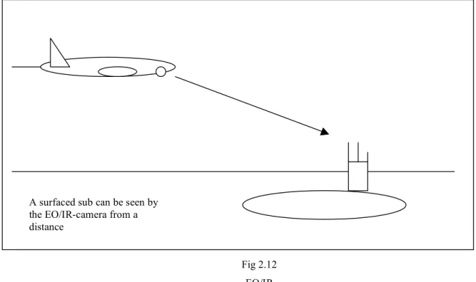
Fig 2.12 EO/IR
An obvious downside to this sensor is that the submarine has to be surfaced if the camera is to be able to classify and provide further details for the aircrew. Because of this simple fact, the modern cameras are of little use when it comes to actually searching for a submerged submarine.
A surfaced sub can be seen by the EO/IR-camera from a distance
2.4 Summary
Antisubmarine warfare (ASW) is a complicated business. The flying crew needs to
understand the environment they are working in and they need to have a working knowledge of the particular equipment they use and how well it might function. Those who are involved in ASW need to have a wealth of material available at all times. Speed of reaction, flexibility to change operating areas quickly and efficiently and the ability to deploy sophisticated buoys are all in the advantage to the aerial ASW platform. They have an array of sensors in addition on board that will help them accomplish their mission, be it covertly following the enemy submarine or hunting it down in order to neutralize her. But as the submarines get quieter and quieter, the aerial ASW sensors are lagging behind, and moving the operational area into littoral waters certainly complicate matters for the aircraft, as well as for other ASW
platforms. The existing sensors do not perform as well close to the shore as they might do out to sea, and in order to stay on top of the game one has to investigate additional methods for detecting the adversary submarine and stay in control of it. This thesis seeks to explore the potential of one such method, and recommends in the end a way forward for meeting the current littoral challenge.
3 – LIDAR technology explained
3.1 Background
The term “LIDAR” is an acronym for LIght Detection And Ranging, and the technology is in
effect based on laser equipment and additional analyzing equipment. LIDAR systems in use are all based on laser technology. The laser is used as an active sensor, emitting light with known characteristics and comparing the transmitted light with the returned signal from the object which it illuminates. Timing of pulses, wavelengths and angles of the returned signals are all part of the analysis of returns that the LIDAR system processes, in order to describe the shape, presence or structure of the illuminated object. Systems that for example measure the depths of coastal waters and lakes from low-altitude aircraft use a scanning, pulsed laser beam. The LIDAR system transmits laser pulses into the water, and analyzes the pulses of light when they return.
The laser – an acronym for “Light Amplification by Stimulation of Radiation” – was
invented in the late 1950s, initially for scientific purposes and industrial applications, and the invention is credited to the two scientists Schawlow and Townes for publishing the article “Infrared and Optical Masers” in 1958 (Schawlow & Townes 1958). A laser has a narrow beam that does not diverge as it travels from the transmitter, and many applications take advantage of this feature for heating, cutting (for instance surgery), etching and illumination (Campbell 2007:239). The further development has exploded in all directions, and in modern times one can hardly get through a normal day without encountering a device relying on laser technology. Further examples of everyday technology that is based on laser are pointers, CD players, printers, scanners and bar code readers.
In the 1970s several agencies including National Aeronautics and Space
Administration (NASA), National Oceanic and Atmospheric Administration (NOAA) and the Defense Mapping Agency (DMA) began developing LIDAR-type sensors for measuring topographic and oceanographic properties (USACE 2002:11-3). Over the past decades, developments in lasers, optics electronics and computers have contributed in making it easier to construct airborne LIDAR systems with varying purposes, and an increasing number are being constructed (Guenther 2006:254).
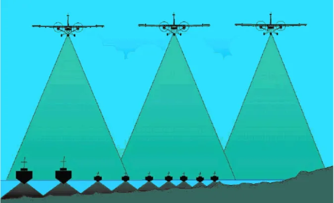
Airborne LIDAR bathymetry is an accurate and cost-effective alternative to
figure 3.1 below). Airborne LIDAR systems can also survey in areas where sonar cannot, like structures above water and over land (Guenther 2006:254). LIDAR has become an essential part of coastal surveying, and large-scale nautical charting has been the main focus for most
of the deployed systems. Like the Swedish Maritime Administration puts it: “the use of a
helicopter-borne laser-beam system is essential, especially in shallow waters and narrow waters in the archipelago” (Nordstrom 2000:37).
Figure 3.1
Airborne vs. surface based surveys
However, as will become clear through this chapter, the technology applied through water has its inherent limitations. Water clarity, attenuation and scattering of the light beam give a fairly shallow working depth in ASW terms. The presented systems at the end of the chapter will show mixed results, and not very impressive ones, even when functioning properly, submariners might claim. Submarine commanders themselves, knowing about the
evolving non-acoustic sensors, are eager to point out that a submarine “can only be detected
one way – by sound – and by going slow it puts out very little sound” (Gelantin 1995:273). And submarine forums and magazines play down the prospect of developing technologies that
In any circumstance, civilian airborne LIDAR systems are accurate and have a high coverage rate for their purposes. The systems are flexible and mobile, and have a relatively low cost per unit area. Although LIDAR-systems are usually used alone, they are generally complementary with other surveying systems, such as sonar (Calder & Penny 1980:1-21). This will be discussed later with regards to the usage and potential of military airborne LIDAR-systems.
To get an understanding of the basic technology that lies behind the LIDAR systems, and look at the factors which play a role in constructing such a system for the desired use, an introduction to LIDAR technology will be presented in this chapter. The performance of existing and future LIDAR capacities will be discussed, as well as factors limiting this performance.
3.2 LIDAR hardware
3.2.1 Laser lightThe laser unit applies an electrical current to a “lasable” material, such as carbon dioxide, argon, helium-neon, rubies, and other less familiar materials. These materials have atoms, molecules or ions that emit light when they return to their normal state after being excited by a stimulus such as electricity. Electricity start the laser, but the key property is that light itself stimulates the lasable material to emit more light and that this light is coherent - it is in phase with the light that stimulated it and composed of a narrow range of wavelengths. Light with these attributes can travel long distances and only diverge slightly, as opposed to “normal” light.
LASER-light
LASER material (nitrogen, helium-neon, ruby crystals)
High-voltage electricity High-voltage electricity
Mirror Partial reflector
LASER cavity
Figure 3.2 Laser in principle
Each separate material provides a specific laser-beam with distinctive characteristics when it comes to wavelength. The laser uses mirrored surfaces to accumulate many pulses in order to increase the intensity of the light beam before it leaves the laser (Campbell 2007:239-249). By knowing the characteristics of the light-beam and timing of the pulses it is possible, with the proper receiving equipment, to record, measure and analyze the returns from different objects. This is what is done by police-officers measuring the velocity of passing cars. They utilize a very simple piece of equipment to illuminate the car with a laser beam, and measure the return based on the known characteristics of the transmitted beam. The calculated result is the speed of the car. The police speedometer is one of the simplest forms of LIDAR usage.
Getting a bit more advanced, one can integrate the laser with the proper electronics, which in turn will arrange laser-pulses in the proper timing-sequence, as opposed to a steady beam, and thus give the transmission the form of incredibly fast pulses of light. Combining this with the appropriate processing of the returned pulses of light, one can start to record and analyse the received bits of information.
The next step would be to feed the light into a system of mirrors, which will redistribute the pulses as a scanning beam like the simplified diagram figure 3.4 shows.
Laser Drive motor Receiver Optics Electronic prosessor Rotating mirrors Electronic prosessor Laser Receiver Figure 3.3 Basic LIDAR
There are several different designs within laser technology, and the above diagram shows only one of these, and in principle. To go into detail of the technology of the laser and the LIDAR themselves is both outside my competence and the scope of this dissertation. I will, however, try to point to some physics factors that affect the usage and further development of such technology. To design a reliable LIDAR system it is necessary to have a thorough understanding of the characteristics of the laser and optics, of the data collection and electronics and as many as possible of the different interactions between the light beam and the environment.
One of the biggest problems that must be solved involves the accurate and reliable determination of the air/water interface for each of the laser pulses. Separate wavelengths within the same scan must be used for this. At least two, widely separated, non-green wavelengths, such as red and infrared (IR), should be used, in order to achieve the highest degree of accuracy for every laser pulse.
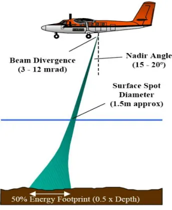
A second problem is the immense difference in magnitude of amplitude dynamic range between the very strong water interface returns and the very weak bottom returns – the difference is often more than six orders of magnitude of amplitude dynamic range (Guenther
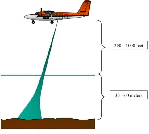
Figure 3.5 Spreading of laser light
300 – 1000 feet
must be handled by the detector and further relayed to the digitizer in accordance with the latter’s input range, after compressing the signals without distorting them.
These complicating factors create great demands to the laser transmitter, as well as the processing equipment. Unfortunately, the pulse energy, pulse-repetition rate, pulse width and reliability under field conditions for laser transmitters have made slow process after the laser was invented (Guenther et al. 2000:7).
The laser pulse repetition rate is a key factor in developing an efficient LIDAR-system. The faster the repetition rate, the better, as the LIDAR will be able to process a greater area in less time. Over the coming years, faster lasers will be needed and likely available, and repetition rates should approach 10.000Hz, with 5mJ/pulse and 1-2 ns pulse widths (Pope et al. 2001:6). The size, weight and power requirements of the laser equipment must decrease in order to facilitate smaller LIDAR-systems. Also, lasers which are tunable according to the given environmental conditions would increase the portfolio of a given
system. The processing challenges will be discussed in the section “3.3 LIDAR software -
Processing the returns”.
3.2.2 Imaging LIDARs
The first airborne LIDARs were profiling lasers, which were pointed directly beneath the aircraft, and would thus be able to map out the elevation profile directly beneath the aircraft. When used primarily to acquire topographic data, or measure the height of the aircraft above ground, these instruments are primarily known as airborne laser altimeters.
In the past decades several technologies have matured, such as data processing equipment and positioning devices, and with these capabilities in place several LIDAR systems are used as remote sensing instruments for collecting detailed information about the Earth’s surface and subsurface environment.
The further development of several technological elements has been crucial, of which three stand out.
Inertial Measurement Units (IMU)
The inertial measurement unit measures the attitude of the aircraft, or the orientation in roll, pitch and heading. Combined with the GPS positional data this information provides an
for the pilots, but is invaluable to airborne surveying equipment as well. The development of laser gyro-stabilized IMUs have made this technology mature during the 1980s and 1990s.
Figure 3.6
Inertial Measurement Units
Global Positioning System (GPS)
An accurate recording of the geographic location of the aircraft is essential to be able to place each recording geographically. The development of the GPS system gives military units as well as civilians an accurate account of their position, and with the system including an accurate time-indication as well the GPS has become absolutely necessary in the design of an accurate LIDAR system.
Using what is known as differential GPS (DGPS) one can input the local error in GPS-positioning (ranges to the satellite derived by an iterative process) and thus generate
corrections (see the stand-alone GPS-equipment in figure 3.6). DGPS positioning is used by almost all LIDAR systems, and has an accuracy of better than 3 meters (Pope et al. 2001:6, Guenther 2006:293). The development of carrier-phase, or kinematic GPS techniques in 1997 eliminated the need to collect concurrent tide measurements (Wozencraft & Lillycrop
Clocks
The always improving science of measuring time has led to highly accurate clocks for precise timing of the laser pulses in the LIDAR systems. As the pulse repetition rate desirably will increase, the development of even quicker and more accurate timing devices has kept pace and must continue to do so in order to achieve the proper processing of every transmitted ray of light.
The accuracy of these three units is paramount for the performance of a LIDAR scanning system. With the units properly integrated, the returned signals into the system can be associated with specific points on the Earth’s surface. The timing capability permits accurate assessment of distance and elevation, which further leads to a detailed image of the environment that is being surveyed (Campbell 2007:241).
3.2.3 The Processor
The pace of the improvements made by the computer industry has been tremendous over the past decades, and these have had an impact on the development of LIDAR systems as well. One of the biggest challenges of the early systems was the lack of capability to process the returned signals. With the computer technology reaching new heights by the week over the last decades, the technology needed to have a thorough processing of the signals have finally reached a point where one is talking about a “mature” technology or science. The algorithms required to analyze each wavelength have been modified and become increasingly more advanced over the years. This has been done after experiencing new factors in light going through water and air during surveying processes (Wozencraft & Lillycrop 2002:4). In addition to analyzing the returns the processor merges the positional information with every signal being returned, thus providing an actual position for every single return. This makes LIDAR-mapping possible.
3.2.4 Design philosophies
Different design philosophies are employed for full-capability systems. They differ in their scan patterns, the power of the laser, the spread of the beam or spot size, swath angle, pulse repetition rate, surface detection strategies, and means of handling the signal-amplitude dynamic range (USACE 2002:11-4, Guenther 2006:263). NASA has deployed a system with
good resolution and accuracy. These factors provide enhanced performance in very shallow waters, but lead to a limited depth capability.
What is important for the design of an aircraft-borne LIDAR system is that the area that can be covered per unit time depends on the laser pulse-repetition rate. Higher rates permit faster aircraft speeds and higher altitudes, in addition to higher survey densities
important for small-object detection (Guenther 2006:5). This combination of pulse energy and width is not an easy set of requirements for laser manufacturers to meet at such high pulse repetition rates.
To increase operational flexibility it is beneficent that the LIDAR system is small, portable and modular in design. In addition it is important to lower the threshold of techno-logical insight needed to operate such a system. The level of automation for the system should increase and thus provide the operator with an understandable and flexible system (Pope et al. 2001:6).
All these factors have to be incorporated in the design of new LIDAR systems: faster pulses, quicker processing and a more flexible and portable module.
3.3 LIDAR Software - Processing the returns
3.3.1 WavelengthIn classical bathymetry one seeks to establish the depth of the water column. To distinguish the returns of the radar-pulses from each other and analyse them it is important to know when and where each pulse enters the water – that is when the change from travelling through air to travelling through water occurs. To know this, it is important to have a designated, steady beam of transmission that will give you this information.
Taking advantage of what we know about the electromagnetic spectrum and the characteristics of water, experience has shown that the best type of laser light for water penetration is a green, or blue-green laser. This light will actually penetrate the water surface, as opposed to the infrared (IR) beams that are reflected off of the surface. Using these two, different characteristics in the beams simultaneously, one can examine the returns from the top and bottom of the water-column and from within the water column itself, with the knowledge of where the green laser hit the water in mind.
The wavelength typically used for IR-beams in LIDAR-equipment is 1064 nm, which is a wavelength that has proven itself suitable for surface detection. What is exceptionally nice
double the frequency of that diverted fraction. The diverted light will then be sent out as a beam in itself. This gives us a wavelength of 532 nm which is the green light needed to penetrate the water-surface (Guenther 2006:265). This feature of splitting one, original beam is playing its part in keeping the hardware small and light.
The wavelength issues of LIDAR for use in water are not as clear-cut as indicated. In an optimal world the equipment would have transmitted two beams, and received two beams. However, the receiver detects several different wavelengths as a result of the original
transmission. Some of the green light is reflected immediately as the beam hits the water surface, although most of the light penetrates the surface. Inversely, some of the IR-light penetrates the surface, although most of the IR-beam is reflected off of the surface once the beam hits the water. In addition, the water-column splits the original green-light (see fig. 3.7) and produces in this way several different wavelengths which are returned to the receiver. This process is known as scattering. Lasers are usually thought of as being highly collimated with a small cross section, as they are in space or over short distances in air. This is not the case in water. Scattering causes even the narrowest beam to expand into a cone with an angle and cross section that increases significantly with depth (Guenther 2006:262).
Laser pulse Receiver field of view Interface reflection Illuminated surface area
Mean water Nadir angle
Vertical depth Unscattered reference path Returning bottom reflected signal Volume
backscatter ”Undercutting” path Multiple scattering