Controlling Remote System using Mobile Telephony
By
Rifat Shahriyar S M Sohan Rifat Reza Joyee
A Thesis Submitted to
Department of Computer Science and Engineering
for the Partial Fulfilment of the Requirements for the Degree of Bachelor of Science
in
Computer Science and Engineering
Department of Computer Science and Engineering Bangladesh University of Engineering and Technology
Certification
The thesis titled”Controlling Remote System using Mobile Telephony” , sub-mitted by Rifat Shahriyar, Student No. 0105037, S M Sohan, Student No. 0105039 and Rifat Reza Joyee, Student No. 0105095, to the Department of Computer Sci-ence and Engineering, Bangladesh University of Engineering and Technology, has been accepted as satisfactory for the partial fulfilment of the requirements for the degree of Bachelor of Science in Computer Science and Engineering and approved as to its style and contents.
Supervisor
——————————— Dr. Md. Mostofa Akbar Associate Professor,
Department of Computer Science and Engineering, Bangladesh University of Engineering and Technology, Dhaka-1000, Bangladesh.
Declaration
We, hereby , declare that the work presented in this thesis is the outcome of the investigation performed by us under the supervision of Dr. Md. Mostofa Akbar, As-sociate Professor, Department of Computer Science and Engineering, Bangladesh University of Engineering and Technology, Dhaka.We also declared that no part of this thesis and thereof has been or is being submitted elsewhere for the award of any degree or diploma.
Signature of the Students
——————— Rifat Shahriyar Student No. 0105037 ————— S M Sohan Student No. 0105039 ———————— Rifat Reza Joyee Student No. 0105095
Acknowledgement
We are grateful to several people for this thesis without whom it won’t be a suc-cess. First of all, our heart felt thanks to our supervisor Dr. Md. Mostofa Akbar for his support and creative directions .We had the autonomy to decide our ways with the progress under his continuous feedback.
Special thanks got toMr. Masud Khan, currently working at Microsoft USA , for sticking to us all the way and helping us with necessary devices and directions. Thanks to Imranul Hoque and Sonia Jahid , currently doing PHD at University of Illinois at Urbana-Champaign, for their help. Without their support we couldn’t implement the prototype which is very important part of this thesis.
Thanks toIftekhar Naimand Enamul Hoquefor providing us valuable informa-tion and sharing their knowledge about the Home Controlling System.
Department of Computer Science and Engineering of Bangladesh University of Engineering and Technology provided us with sound working environment and other catalysts to work for an ideal research. We used the laboratories and all the staffs were helpful and friendly to us.
Last but not the least, we acknowledge the contribution of our family members for being with us and encouraging us all the way, without their sacrifice we couldn’t end up being successful.
Abstract
In modern days, we have to be in touch with various high-tech machineries and equipments to get our jobs done and make our lives easier. Too often these ma-chineries serve very important purposes and sometimes require continuous mon-itoring. But it’s not always feasible to be physically near to the system. So, to be in touch with this sort of important systems by not being physically close, we need some sort of remote solution. The remote solution should unleash the restrictions due to physical distance yet provides enough reliability even from distance.
We came to know about some commercially available products which allow re-mote systems controlling through internet. Internet is undoubtedly emerging; yet, it lacks the true sense of real mobility and security, making the remote system controlling a limited term than it is supposed to be.
In search of true a remote and adequately secure solution to be really effective and practicable, which can be a better choice to mobile telephony? Mobile phones have become almost an inseparable part of civil lives today. We are all familiar with the CALL and SMS services of mobile phones and use it extensively in our daily lives. Also enhanced data rate services like GPRS and EDGE are common in today’s world and it brings the internet to the mobile phones. Keeping the mobile telephony in mind, we tried to analyze the existing services and solutions to the problem of true remote system controlling and came up with some innovative ideas to utilize the power of mobile telephony. We researched and implemented the mechanism so that the ordinary services of the mobile phones can be leveraged to communicate with and control the remote systems.
Contents
1 Introduction 1
1.1 Definitions of a Remote System . . . 1
1.2 Motivation Behind Controlling Remote System . . . 1
1.3 Available Media . . . 2
1.3.1 Internet . . . 2
1.3.2 Mobile Telephony . . . 2
1.4 Scope . . . 2
1.5 Organization of the Chapters . . . 3
2 Background 5 2.1 Mobile Telephony . . . 5
2.2 X10 Active Home Controller Pro . . . 6
2.3 Java Specification Request(JSR) . . . 7
2.4 Java 2 Micro Edition(J2ME) . . . 7
2.5 Java Native Interface (JNI) . . . 10
2.6 Wireless Ad-hoc Network . . . 10
3 Web Server Based Solution 12 3.1 Definition . . . 12
3.2 Understanding the Hyper Text Transfer Protocol (HTTP) . . . 13
3.3 Mobile Connectivity . . . 15
3.4 Pseudo Code . . . 16
3.4.1 Mobile Web Client . . . 16
3.5 Pros and Cons . . . 17
3.5.1 Pros . . . 17
3.5.2 Cons . . . 18
4 NOKIA FBUS Based Solution 19 4.1 Definition . . . 19
4.2 Understanding the FBUS Protocol . . . 19
4.2.1 Basic Packet Format . . . 20
4.2.2 Format of Packet from Computer . . . 20
4.2.3 Format of ACK from Computer . . . 21
4.2.4 Format of Packet from Mobile Phones . . . 22
4.2.5 Format of ACK from Mobile Phones . . . 22
4.2.6 Format of SMS Submit from Computer . . . 22
4.2.7 Process of SMS Decoding . . . 24
4.3 Mobile Connectivity . . . 24
4.4 Pseudo Code . . . 25
4.5 Usage . . . 26
4.6 Pros and Cons . . . 26
4.6.1 Pros . . . 26
4.6.2 Cons . . . 26
5 Bluetooth Based Solution 27 5.1 Definition . . . 27
5.2 Understanding the Bluetooth Communication . . . 28
5.3 Mobile Connectivity . . . 30 5.3.1 Stack Initialization . . . 31 5.3.2 Device Management . . . 31 5.3.3 Device Discovery . . . 32 5.3.4 Service Discovery . . . 32 5.3.5 Service Registration . . . 33 5.3.6 Communication . . . 34 5.4 Pseudo Code . . . 35
5.5 Pros and Cons . . . 35
5.5.1 Pros . . . 35
5.5.2 Cons . . . 36
6 AT Command Based Solution 37 6.1 Definition . . . 37
6.2 Understanding the AT Commands . . . 37
6.2.1 Format of AT Commands . . . 37
6.2.2 SMS Related AT Commands . . . 38
6.3 Mobile Connectivity . . . 39
6.4 Pseudo Code . . . 39
6.5 Pros and Cons . . . 40
6.5.1 Pros . . . 40
6.5.2 Cons . . . 40
7 Demonstrating Prototype 41 7.1 Brief Comparison of Different Alternative Solutions . . . 41
7.2 Description of the Prototype . . . 42
7.2.1 Remote Mobile . . . 42
7.2.2 Home Mobile . . . 43
7.2.3 Home Computer . . . 43
7.2.4 X10 Home Controller Package . . . 44
8 Conclusion 46 8.1 Summary . . . 46
8.2 Future Expansion Possibilities . . . 47
A 48 A.1 Web Server Based Solution . . . 48
A.2 NOKIA FBUS Based Solution . . . 51
A.3 Bluetooth Based Solution . . . 58
List of Tables
3.1 HTTP Response Codes . . . 15
4.1 FBUS packet format from Computer . . . 21
4.2 FBUS ACK format from Computer . . . 21
4.3 FBUS packet format from Mobile Phone . . . 22
List of Figures
2.1 Java Mirco Edition Components . . . 9
3.1 Block Diagram : Web Server Based Solution . . . 15
4.1 NOKIA FBUS Connection . . . 20
4.2 Block Diagram : NOKIA FBUS Based Solution . . . 25
5.1 Block Diagram : Bluetooh Based Solution . . . 31
6.1 Block Diagram : AT Command Based Solution . . . 39
Chapter 1
Introduction
1.1
Definitions of a Remote System
We consider the ’System’ to be a concept that encapsulates a bunch of machines and instruments grouped to perform some tasks. An example of such a system is a cell phone tower or a manufacturing house or even a home or anything that is equipped with electrically or electronically controlled devices.
We define ’Remote’ to be a place anywhere on the earth. So, conceptually remote controlling a system is global remote controlling that is usable for any sort of control involving machines and instruments.
1.2
Motivation Behind Controlling Remote System
The motivations behind the goal to control such remote systems are simple. It’s not always feasible to be physically near to the system setup and still sometimes it’s very important to control it. For an example, a smart remote controller may enable us to track the surveillance from anywhere. So, it takes the control of the home beyond the home and to the hands of the people. And if a simple mobile phone takes the added responsibility to control the remote system, the control is reachable from almost everywhere people travels and lives on earth. This sort of high end technology is supposed to facilitate the different life easing utilities to a
new age and bringing things out of the box to as near as one’s palm.
1.3
Available Media
1.3.1 Internet
Of all the available media, Internet is a good example of the remote communica-tion. Internet places virtually no bounds on geographical placement and is thus considered ’enough’ remote by our definition. But internet is a place crowded with various types of traffics, often hostile to each other. Security vulnerability is the most striking alert point of the internet. Whenever a web based application goes live, a lot of efforts has to take place before it can be said to be secured, if at all. When we say remote control, we want to make sure no malicious party ever gains control and abolishes everything. Also to use web, it requires resources like flawless internet connections and hosting servers, which may not always fit to the concept of remote controlling systems.
1.3.2 Mobile Telephony
Another candidate solution to this problem is the use of mobile telephony. Mobile telephony offers a wide range of communication services like voice and data trans-fer through SMS and other enhanced data transtrans-fer protocols like GPRS, EDGE [1] at a relatively low price and at a wide variety of places on earth. In the mean time, the security is better achieved by the use of strict traffic control. We adhered to this method for our approach to the remote system controlling because of its unparallel availability and modest security at the affordable price.
1.4
Scope
The main goal of this project is to find out the feasible ways to leverage the mobile telephony using the existing services but redefining the trivial purposes they serve. So, we investigated the different ways we could use the cell phones to go beyond making calls and sending SMS for taking care of personal interests and devised
some ways to implement the remote control, which is ’Remote’ and conceptually can be used at any System.
Conceptually it is a generic solution for controlling remote systems. To make it a reality and also to demonstrate its power we started with the simple task of controlling a home remotely using mobile telephony. A home is also a System in the context that there is a setup of various electrical and electronic machines and instruments. Although the televisions and air conditioners come with some sort of small range remote controllers, we look beyond the small range and take it to any range indeed. So, although the water motor or the infrared security system doesn’t come with such a remote controller, it’s perfectly possible to leverage the technology of mobile telephony to extend it. And also we don’t need to carry one remote controller for each of the devices we wish to control; rather we can do this just by using our mobile phone, which we generally carry anyway. Even more, we don’t have to subscribe to any other services like internet or whatsoever beyond the normal services we get from our traditional mobile phones, which makes it very handy indeed.
It’s better to leverage the available home controllers than to devise one from scratch to aid this goal. Because there are standardized home controllers in the market and they offer wide coverage of controllable appliances. X10 is one of the best candidates in the home controller manufacturers [2]. We left the home appli-ances controlling part to the X10 and concentrated on the communication between the mobile phone and the X10 controller.
1.5
Organization of the Chapters
In the following chapters, we represent the various candidate solutions to remote controlling using telephony. Chapter two provides some definitions and back-grounds to facilitate the reader in understanding the terms and technologies used throughout this document. Chapters three to six documents the implementation guidelines of various ways for extending the communication of mobile telephony
for controlling the home controller which is used as a prototype of generic remote systems.
Chapter 2
Background
This chapter introduces the mostly used terms and provides basic backgrounds of the participants in the various solutions to the remote system controlling prob-lem which we devised and impprob-lemented.
2.1
Mobile Telephony
In telecommunication, telephony encompasses the general use of equipment to provide voice communication over distances, specifically by connecting telephones to each other. The term mobile telephony is derived from original telephony to de-note the communication that facilitates mobility using wireless technology. Mobile telephony offers services like voice and data transfer. Data transfer is done us-ing SMS and also some other enhanced data rate services like GPRS and EDGE provides internet access facilities to the mobile phones.
Short Message Service (SMS) is a telecommunications protocol that allows the sending of ”short” (160 characters or less) text messages. It is available on most digital mobile phones and some personal digital assistants with onboard wire-less telecommunications. Devices which can connect to mobile phones and PDAs through protocols such as Bluetooth and AT command can also sometimes use that link to send SMS messages over the wireless network. The usability of the inter-person SMS can be used to leverage for the controller we wish to design.
GPRS (General Packet Radio Service) is the most used wireless data service, avail-able now with almost every GSM network. GPRS is a connectivity solution based on Internet Protocols that supports a wide range of enterprise and consumer ap-plications. With throughput rates of up to 40 kbit/s, users have a similar access speed to a dial-up modem but with the convenience of being able to connect from anywhere. GPRS customers enjoy advanced, feature-rich data services such as color Internet browsing, e-mail on the move, and powerful visual communications such as video streaming, multimedia messages and location-based services.
Further enhancements to GSM networks are provided by Enhanced Data rates for GSM Evolution (EDGE) technology. EDGE provides up to three times the data capacity of GPRS. Using EDGE, operators can handle three times more subscribers than GPRS; triple their data rate per subscriber, or add extra capacity to their voice communications. EDGE allows the delivery of advanced mobile services such as the downloading of video and music clips, full multimedia messaging, high-speed color Internet access and e-mail on the move. [1]
2.2
X10 Active Home Controller Pro
X10 controller comes as a package that has one controller module and other appliance modules categorized by their classes like lights, fans and so on. The controller connects to a computer using USB connectivity. It can be instructed using the provided software from computer and also from the remote controller that comes with the package. An appliance specific module or generic module is plugged in between the controller and the appliances. The controller directly impacts the modules and not the appliances attached with the modules. So, the devices are completely unaware of the presence of the X10 home controlling and this is why X10 doesn’t limit its operations to some specific vendors.
X10 controller uses the power line to send and receive commands to the modules. This signal is passed using a bandwidth that doesn’t interfere with the existing power connections.
To control a specific appliance of many so connected, X10 uses an addressing mechanism to detect the desired one. This addressing is set in the appliance mod-ules prior to connecting it and can be changed at anytime. Whenever X10 controller has to send some commands, it broadcasts the command to the power line. The command contains the address of the device that is intended to control. So, the module that has an address matching with the address in the command, responds immediately. This way, it handles a specific request issued by the controller to control an appliance. [2]
2.3
Java Specification Request(JSR)
Java Specification Requests (JSR) are the actual descriptions of proposed and final specifications for the Java platform. At any one time there are numerous JSRs moving through the review and approval process. JSR - 82 one of the JSRs and used for programming Bluetooth in java and we used it in our implementation (refer to chapter 05 for details). [3]
2.4
Java 2 Micro Edition(J2ME)
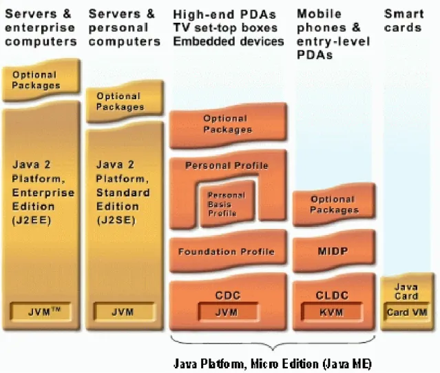
Java Platform, Micro Edition (Java ME) is the most ubiquitous application plat-form for mobile devices across the globe. It provides a robust, flexible environment for applications running on a broad range of other embedded devices, such as mo-bile phones, PDAs, TV set-top boxes, and printers. The Java ME platform includes flexible user interfaces, a robust security model, a broad range of built-in network protocols, and extensive support for networked and offline applications that can be downloaded dynamically. Applications based on Java ME software are portable across a wide range of devices, yet leveraging each device’s native capabilities.
The Java ME platform is deployed on billions of devices, supported by leading tool vendors, and used by companies worldwide. In short, it is the platform of choice for today’s consumer and embedded devices. Java ME technology was originally created in order to deal with the constraints associated with building applications
for small devices. For this purpose Sun defined the basics for Java ME technology to fit such a limited environment and make it possible to create Java applications running on small devices with limited memory, display and power capacity. Java ME platform is a collection of technologies and specifications that can be combined to construct a complete Java runtime environment specifically to fit the require-ments of a particular device or market. This offers a flexibility and co-existence for all the players in the eco-system to seamlessly cooperate to offer the most appealing experience for the end-user.
The Java ME technology is based on three elements
1. A configuration provides the most basic set of libraries and virtual machine capabilities for a broad range of devices.
2. A profile is a set of APIs that support a narrower range of devices. 3. An optional package is a set of technology-specific APIs.
Over time the Java ME platform has been divided into two base configurations, one to fit small mobile devices and one to be targeted towards more capable mobile devices like smart-phones and set top boxes. The configuration for small devices is called the Connected Limited Device Profile (CLDC) and the more capable configu-ration is called the Connected Device Profile (CDC).The figure below represents an overview of the components of Java ME technology and how it relates to the other Java Technologies.
Configuration for Small Devices - The Connected Limited Device Configuration (CLDC) The configuration targeting resource-constraint devices like mobile phones is called the Connected Limited Device Configuration (CLDC). It is specifically designed to meet the needs for a Java platform to run on devices with limited memory, processing power and graphical capabilities. On top of the different configurations Java ME platform also specifies a number of profiles defining a set of higher-level APIs that further define the application. A widely adopted example is to combine the CLDC with the Mobile Information Device Profile (MIDP) to provide a complete Java appli-cation environment for mobile phones and other devices with similar capabilities.
Figure 2.1: Java Mirco Edition Components
With the configuration and profiles the actual application then resides, using the different available APIs in the profile. For a CLDC and MIDP environment, which is typically what most mobile devices today are implemented with, a MIDlet is then created. A MIDlet is the application created by a Java ME software developer, such as a game, a business application or other mobile features. These MIDlets can be written once and run on every available device conforming with the specifications for Java ME technology. The MIDlet can reside on a repository somewhere in the ecosystem and the end user can search for a specific type of application and having it downloaded over the air to his/her device.
Configuration for More Capable Devices and SmartPhones - The Connected Device Configura-tion (CDC) The configuration targeted larger devices with more capacity and with a
network-connection, like high-end personal digital assistants, and set-top boxes, is called the Connected Device Profile (CDC). The goals of the CDC configuration is to leverage technology skills and developer tools based on the Java Platform Standard Edition (SE), and to support the feature sets of a broad range of connected devices while fitting within their resource constraints.
2.5
Java Native Interface (JNI)
The Java Native Interface (JNI) is the native programming interface for Java that is part of the JDK. By writing programs using the JNI, a code becomes completely portable across all platforms. The JNI allows Java code that runs within a Java Virtual Machine (VM) to operate with applications and libraries written in other languages, such as C, C++, and assembly. Programmers use the JNI to write na-tive methods to handle those situations when an application cannot be written entirely in the Java programming language. A few examples of such situations are given below.
1. The standard Java class library may not support the platform-dependent fea-tures needed by an application.
2. For using available library or application written in another programming lan-guage and conforming to Java applications.
3. Time-critical codes are typically written in a lower-level programming language, such as assembly, and then can be accessed by Java via JNI. [4]
2.6
Wireless Ad-hoc Network
A wireless ad-hoc network is a computer network in which the communication links are wireless. The network is ad-hoc because each node is willing to forward data for other nodes, and so the determination of which nodes forward data is made dynamically based on the network connectivity. This is in contrast to older network technologies in which some designated nodes, usually with custom hardware and variously known as routers, switches, hubs, and firewalls, perform the task of
forwarding the data. Minimal configuration and quick deployment make ad hoc networks suitable for various purposes.
Chapter 3
Web Server Based Solution
3.1
Definition
Web servers are the hearts of the modern day communication networks. After certain improvements the web servers reached into a stable and powerful state to-day. At its early life, it was responsible for receiving and handling requests from the web clients like different browsers and applications via Hyper Text Transfer Pro-tocol(HTTP). The communication started by the issuing of a request from the Web client. Each Web server handled the request and sent a response back to the Web client. After that, the Web server closed the connection and released all resources involved to fulfill the request. It was necessary to release all the acquired resources because the Web server was supposed to take care of thousands of requests on a short time and also most of the Web pages were only simple static HTML pages. This was termed as ’stateless’ because no state information was held at the Web server for subsequent requests from the Web client.
These days, things improved a lot. The Web servers are capable of handling re-quests for dynamic pages that are generated on the fly depending on the particular request from the Web client. The concept of true ’statelessness’ is no more held as Web servers also have the ability to store data across the Web page requests, which opens the new opportunity of Web applications to come to existence by com-bining the Web pages. Because many Web sites are set up as Web applications
containing many Web pages, the idea of a Web server delivering a single page to the Web browser and closing the connection is rather outdated. Web servers now implement ”keep alive” features for connections that make the Web servers keep the connections to the Web browsers open for a period of time with anticipation of additional page requests from a Web browser.
The most commonly used Web servers are Microsoft Windows based Microsoft IIS (Internet Information Service) and open source Apache and Apache Tomcat for multi platform support.
3.2
Understanding the Hyper Text Transfer Protocol (HTTP)
HTTP is the most used text-based communication protocol that is used by the Web client to request Web pages from the Web server and by the Web server to send responses back to the Web browser. Standard ports for HTTP and secure HTTP (HTTPS) are 80 and 443 respectively.A brief description of the protocol is given next.
GET /index.html HTTP/1.1 Host: www.helloworld.com
This is a simple form of the text based request sent from the Web client to Web server. The components are as
follows:-a. GET - the name of the method to invoke at the server. b. /index.html - the name of the page requested.
c. HTTP/1.1 - the protocol version. d. Host - the Web servers address.
Although the full protocol is not reflected in this small example, it lays down the foundation to discuss about the protocol. Several other lines can be appended to this example to facilitate more options and particulars. Brief descriptions about the two most commonly used methods are given next.
POST -Used to send data as a part of the message body instead of as a part of the page query. These data are not typically cached and no particular constraint is applied on the data length.
GET -Used to send data as a part of the message as a part of the page query. These data are typically cached and constraint a maximum length of data to be transferred.
For a complete list of the methods see [5].
The typical response from a Web server looks like the following:
HTTP/1.1 200 OK
Server: Microsoft-IIS/6.0 Content-type: text/html Content-length: 38
<html><body>Hello World</body></html>
The semantics of the above example is given next:
a. HTTP/1.1 200 OK - the protocol version.
b. Server: Microsoft-IIS/6.0 - the name and version of the Web server. c. Content-type: text/html - the mime type of the attached content. d. Content-length: 38 - the length in bytes of the response.
e. <html><body>Hello World</body></html> - the content to be displayed in the Web client.
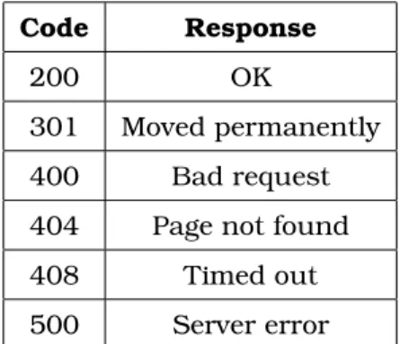
Descriptions of Commonly encountered response codes are as described in code and response format:
Code Response
200 OK
301 Moved permanently
400 Bad request
404 Page not found
408 Timed out
500 Server error Table 3.1: HTTP Response Codes
3.3
Mobile Connectivity
Java (J2ME and J2SE) enabled cell phones can connect to web server easily. One of the widely used constructs to communicate with Web server is the Java Servlet.
Figure 3.1: Block Diagram : Web Server Based Solution
The Web client can issue HTTP Request to the servlet . Java enabled cell phones can connect to a servlet using the HttpConnection, which is the heart of this com-munication. Using HttpConnection the various parameters of the connection can be specified. To connect to the servlet the cell phones have to undertake following activities:
b. Set the HttpRequest type as GET or POST.
c. Set the ”User-Agent” to ”Profile/MIDP-1.0 Configuration/CLDC-1.0”. d. Set the ”Content-Language” to ”en-US”.
e. Open the OutputStream and perform the writing if necessary. f. Open the InputStream and perform the reading if necessary. g. Close the streams.
h. Close the HttpConnection.
The servlet have to be setup initially to serve the mobile clients. The sequences of steps are:
a. The Servlet has an init () method which is called during initialization for allocat-ing resources necessary to serve the requests.
b. It contains a function named doXXX () for handling any HTTP POST or HTTP GET requests initiated by the Web client.
c. The Servlet has a destroy () method which is invoked to clean up the allocated resources.
3.4
Pseudo Code
3.4.1 Mobile Web Client Algorithm : mobileClient
Begin
1. Take input from the user.
2. Validate user input and notify if validation fails. 3. Connect to the Web server.
5. If connection establishes, send the request containing user data to the Web server.
6. Else, notify failure message to the user.
7. Retrieve the response and take necessary actions. 8. Go to step one until user aborts the application.
End
3.4.2 Computer Web Client Algorithm : computerClient
Begin
1. Connect to the Web server.
2. Repeat the following steps until user aborts. 3. Issue request to the Web server.
4. Parse server response.
5. If response contains useful information, take necessary actions. 6. Wait for a specified time.
End
3.5
Pros and Cons
3.5.1 Pros
1. It enlarges the scope of the usability of the internet beyond the computers. 2. Web servers are equipped with high levels of performance optimization and se-curity implementations. So, using a Web server in between the two communicating ends it allows one to take the full advantage of the services provided by the Web servers.
3.5.2 Cons
1. The Web server requires hosting the server side application at a designated server, which adds cost overhead and maintenance issues.
2. Internet connectivity is required for both the mobile device and the home com-puter, which also adds cost overhead.
3. The internet is a place with lots of scopes for security vulnerability and it incurs risk on the communication as well.
4. Web servers are supposed to be best used as a server for complex services to a wide number of clients. But using it to pass the messages from one end to the other does not seem to be intuitive and fails to utilize the true potential of a Web server.
Chapter 4
NOKIA FBUS Based Solution
4.1
Definition
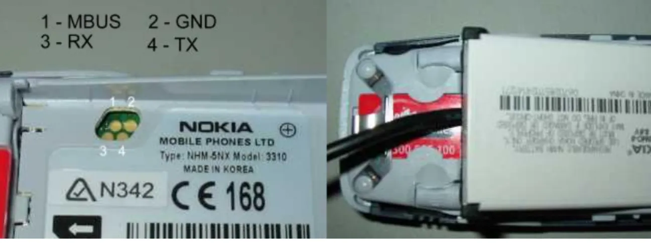
Most Nokia phones come with a default support of M-Bus and F-Bus protocols mainly for low level controlling of the devices like flushing memories, installing operating systems. M-Bus is a one pin bi-directional bus for both transmitting and receiving data from the phone. It is slow and only half-duplex. F-Bus is the later high-speed full-duplex bus and very similar to standard serial port. For this we choose F-BUS over M-BUS for communicating mobile phones with computer.
F-BUS, a proprietary protocol of Nokia, offers a completely bidirectional commu-nication between a mobile phone and a computer through SMS. This protocol is not open to public. To use the F-BUS a special kind of connectivity cable is used instead of the usual cables shipped with the mobile phones.
4.2
Understanding the FBUS Protocol
The Nokia protocol has a series of commands that allow the user to make calls, send and get SMS messages and lots more at the very low level. The protocol is discussed in terms of the functionalities required to send and receive SMS to and from a computer.
Figure 4.1: NOKIA FBUS Connection 4.2.1 Basic Packet Format
Packets sent from the ’phone must be acknowledged by the PC via a special packet and vice versa. Most communication takes the form of:
a. PC sends some type of ”request” or command packet. b. Mobile phone sends an acknowledgement.
c. Mobile phone sends some response to the request packet. d. PC sends acknowledgment.
4.2.2 Format of Packet from Computer
Byte 0: This is the F-Bus Frame ID. For cable connection it is 0x1E and for Infrared it is 0x1C.
Byte 1: This is the destination address. When sending data, it’s the mobile phone’s device ID byte. It is supposed to be same for a mobile phone set (we used 0x00).
Byte 2: This is the source address. When sending data, it’s the PC’s device ID byte (we used 0x0C).
Byte 3: This is the message type or ’command’. e.g. 0xD1 is ’Get hardware and software version’.
Byte 4-5: Byte 4 and 5 holds the message length in bytes. Byte 4 is the MSB and byte 5 is the LSB
Byte 6 and following: The data segment occupies the number of bytes equal to the message length. Most Nokia phones are 16 bit phones and to end up in an even
address, it may be required to pad up the address to the next lowest even number. The last byte in the data segment (Byte 12 above) is the sequence number. : The last 3 bits of these byte increments from 0 to 7 for each frame. This part needs to be sent back to the phone in the acknowledge frame.
Bytes after the data segment: Two checksum bytes are appended to the end of the packet. The second to last byte is always the odd checksum byte and the last byte is the even checksum byte. The checksum is calculated by XORing all the odd bytes and placing the result in the odd Checksum location and then XORing the even bytes and then placing the result in the even byte. So the frame structure is as follows
1E 00 0C Type Len Message Seq No Padding byte if necessary Checksum Table 4.1: FBUS packet format from Computer
4.2.3 Format of ACK from Computer
Byte 0: Same as packet send from computer.
Byte 1: Same as packet send from computer.
Byte 2: Same as packet send from computer.
Byte 3: This is the message type or ’command’. For acknowledgment it is 0x7F.
Byte 4-5: This is the length of the message which is always 0x02.
Byte 6: It corresponds to original message type.
Byte 7: It is the sequence number. The last 3 bits indicate sequence number of packet being acknowledged.
Byte 8-9: The 8th byte is the odd checksum byte and the 9th byte is the even checksum byte. So the frame structure is as follows
1E 00 0C 7F 00 Len Type Seq No Checksum
4.2.4 Format of Packet from Mobile Phones
This is the same format as the packet sent from Computer. The only difference is the source and destination address are swapped .So the frame structure is as follows
1E 0C 00 Type Len Message Seq No Padding byte if necessary Checksum Table 4.3: FBUS packet format from Mobile Phone
4.2.5 Format of ACK from Mobile Phones
This is the same format as the ack sent from Computer. The only difference is the source and destination address are swapped .So the frame structure is as follows
1E 0C 00 7F 00 Len Type Seq No Checksum
Table 4.4: FBUS ACK format from Mobile Phone
4.2.6 Format of SMS Submit from Computer
Byte 0: This is the F-Bus Frame ID.
Byte 1: This is the destination address.
Byte 2: This is the source address.
Byte 3: This is the message type or ’command’. E.g. 0x02 is used for SMS.
Byte 4-5:Byte 4 and 5 holds the message length in bytes. Byte 4 is the MSB and byte 5 is the LSB.
Byte 6 to 8: This is the start of the SMS frame header. It contains 0x00, 0x01, and 0x00.
Byte 9 to 11: This is used to indicate that SMS is sending. It contains 0x01, 0x02, and 0x00.
and SMS Centre Phone Number.
Byte 13: This is SMSC number type e.g. 0x81-unknown 0x91-international 0xA1-national.
Byte 14 to 23: This is SMS Centre Phone Number in octet format.
Byte 24: This is message type. XXXX XXX1 means SMS Submit - The short mes-sage is transmitted from the Mobile Station (MS) to the Service Centre (SC). XXXX XXX0 means SMS Deliver - The short message is transmitted from the SC to the MS.
Byte 25: This is Message Reference if SMS Deliver and Validity Indicator used.
Byte 26: This is the Protocol ID.
Byte 27: This is the Data Coding Scheme.
Byte 28: This is the message length in 7 bit characters. It is the size of the un-packed message.
Byte 29: This is the Destination’s number length in semi-octets.
Byte 30: This is Destination’s number type e.g. 0x81-unknown, 0x91-international, 0xA1-national
Byte 31 to 40: This is the Destination’s Phone Number in Octet format.
Byte 41: This is the Validity-Period Code. It defines the time period during which the originator considers the short message to be valid.
Byte 42 to 47: This is the service centre time stamp For SMS-Deliver.
Byte 48 to following: The data segment occupies the number of bytes equal to the message length. It is the message packed into 7 bit characters using SMS Point-to-Point Character Packing. As most Nokia phones are 16 bit phones and to end up in an even address, it may be required to pad up the address to the next lowest even number. The last byte in the data segment (Byte 12 above) is the sequence number. : The last 3 bits of these byte increments from 0 to 7 for each frame.
Bytes after the data segment: Two checksum bytes are appended to the end of the packet. The second to last byte is always the odd checksum byte and the last byte is the even checksum byte.
4.2.7 Process of SMS Decoding
The SMS sent must be decoded in order to fit it in the packet. The decoding of the String ’hello’ is described below for the clear understanding of the decoding process.
The ASCII characters and binary of ’hello’ are given below h e l l o (ASCII Characters)
68 65 6C 6C 6F (In hexadecimal)
1101000 1100101 1101100 1101100 1101111 (In Binary)
The first byte in the string is on the right. The least significant bit is then displayed on the left with the most significant bit on the left. Shown below is the same string of ’hello’ just displayed backwards. Then it’s just a matter to dividing the binary values into bytes starting with the first character in the string. (Start from right and go to left.) The first decoded byte is simply the first 7 bits of the first character with the first bit of the second character added to the end as shown below. The next decoded byte is then the remaining 6 bits from the second character with two bits of the third byte added to the end. This process just keeps going until all characters are decoded. The last decoded byte is the remaining bits from the last character with the most significant bits packed with zeros.
6F 6C 6C 65 68
1101111 1101100 1101100 1100101 1101000 (The ASCII characters shown in binary)
110 11111101 10011011 00110010 11101000 (The above binary just split into 8 bit segments)
06 FD 9B 32 E8 (The 8 bit segments decoded into hex)
The message ’hello’ is therefore E8 32 9B FD 06 when packed. For more details on FBUS see [6]
4.3
Mobile Connectivity
Nokia phones can connect to the computer using F-BUS protocol. The F-BUS data cable is serial type for the computer side and 3 or 4 or 5 pin special connectors for
connecting the mobile phone.
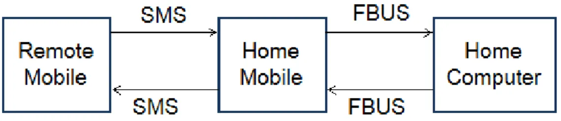
Figure 4.2: Block Diagram : NOKIA FBUS Based Solution
The setup starts with some initial packet and acknowledgment transfer between the computer and mobile phone. When a SMS is received in the mobile phone then it is automatically read by the computer using the F-BUS protocol. Then the computer processes the SMS as required. Moreover the computer can send SMS to any mobile using the mobile connected with it F-BUS protocol. So using F-BUS it is possible to communicate between mobile phone and computer through SMS.
4.4
Pseudo Code
Algorithm : FBUSTransceiver
Begin
1. Perform connection initialization operations 2. Poll the connected port for signals
3. Upon receiving the SMS received signal get the SMS
4. Send acknowledgement data
5. Authenticate and process the data
6. Go to step 2
4.5
Usage
1. If equipped with a standard PCB and appropriate ports, the home mobile can be used as an SDK to provide mobile connectivity with a computer or even micro-controllers.
2. It will suit most for places where internet connection is not available or afford-able but a small scale mobile remote controlling mechanism is required.
4.6
Pros and Cons
4.6.1 Pros
1. This is cost effective in the sense that the communication can leverage the cheapest Nokia mobile phones to serve as the home mobile.
2. It depends on the SMS protocol, making it available at almost everywhere people travel now a days. Also, it doesn’t require any server setup or internet communi-cation to serve the underlying purpose.
4.6.2 Cons
1.The F-Bus protocol is a proprietary one and it’s hard to write robust computer programs to handle data at the lowest level with the mere support that is available in the reach on internet and articles written by some professionals.
2. The connecting cable to the F-Bus is a clumsy process as opposed to the regular connectivity cables, making it unfit to be used as a mobile phone at home.
3. F-Bus is objected to be used with very low level programming, which is not intuitive to be used in our area of interest and suits most to applications like phone memory flushing and installing operating systems.
Chapter 5
Bluetooth Based Solution
5.1
Definition
Bluetooth wireless technology stands in the way of traditional short-range wired communications technology connecting portable and/or fixed devices while main-taining high levels of security. It obsoletes wires between your workstation, mouse, laptop computer, music head-phones etc. The key features of Bluetooth technol-ogy are robustness, low power yet low cost. The Bluetooth specification sets the standard for a wide range of devices to connect and communicate with each other.
Bluetooth technology has achieved global acceptance such that any Bluetooth enabled device, almost everywhere in the world, can connect to other Bluetooth enabled devices with a minimal effort. Bluetooth enabled electronic devices con-nect and communicate wirelessly through short-range ad hoc networks known as Piconets. One device can connect to at most seven other devices simultaneously within a single Piconet and can also be a part of several Piconets. Piconets are established dynamically and automatically as Bluetooth enabled devices enter and leave radio proximity.
A fundamental strength of Bluetooth wireless technology is the ability to simul-taneously handle both data and voice transmissions, making it most feasible for handheld devices. A wide range of innovations like hands-free headsets, printing
and fax utilities and so on are facilitated by the Bluetooth protocol. [7]
5.2
Understanding the Bluetooth Communication
The document has limited the study of Bluetooth to the Application Layer. So the physical architecture details are beyond the scope of this document. Nevertheless the document provides glimpses of some physical layer information as necessary.
Due to the ad-hoc nature of Bluetooth networks, Bluetooth devices naturally move in and out of the range of a Piconet frequently. Bluetooth devices must there-fore have the ability to discover nearby Bluetooth devices. When a new Bluetooth device is discovered, a service discovery may be initiated in order to determine which services the device is offering.
The Bluetooth Specification refers to the device discovery operation as inquiry. During the inquiry process the inquiring Bluetooth device will receive the Blue-tooth address and clock from nearby discoverable devices. The inquiring device then identifies the other devices by their Bluetooth address and is also able to synchronize the frequency hopping with discovered devices, using their Bluetooth address and clock.
Devices make themselves discoverable by entering the inquiry scan mode. In this mode frequency hopping is slower than usual rate because the device spends a relatively longer period of time on each channel. This increases the possibility of detecting inquiring devices. Discoverable devices make use of an Inquiry Access Code (IAC) for device discovery. The General Inquiry Access Code (GIAC) and the Limited Inquiry Access Code (LIAC) are the types of Inquiry Access Code. The GIAC is used when a device is general discoverable implying it will be discoverable for an undefined period of time. The LIAC is used when a device will be discoverable for only a limited period of time.
Different Bluetooth devices offer different sets of services. Hence, a Bluetooth device needs to do a service discovery on a remote device in order to obtain in-formation about available services. Service searches can be of a general nature by polling a device for all available services, but can also be narrowed down to find just a single service. The service discovery process uses the Service Discovery Protocol (SDP). A SDP client must issue SDP requests to a SDP server to retrieve information from the server’s service records. Bluetooth devices keep information about their Bluetooth services in a Service Discovery Database (SDDB). The SDDB contains service record entries, where each service record contains attributes de-scribing a particular service. Each service has its own entry in the SDDB. Remote devices can retrieve service records during service discovery and possesses all in-formation required to use the services described. The Universally Unique Identifier (UUID) is used for identifying services, protocols and profiles. A UUID is a 128-bit identifier that is guaranteed to be unique across all time and space. The Blue-tooth technology uses different variants of UUIDs, short UUIDs and long UUIDs, to reduce the burden of storing and transferring 128-bit UUID values. A range of short UUID values has been pre-allocated for often-used services, protocols and profiles and is listed in the Bluetooth Assigned Numbers document on the Blue-tooth Membership website. Generic Access Profile (GAP) The basis for all profiles in the Bluetooth system. The GAP defines basic Bluetooth functionality like setting up L2CAP links, handling security modes and discoverable modes and primitive data transfers. That’s why it falls into our area of interest.
Authentication is performed using bonding and pairing .Bonding is the procedure of a Bluetooth device authenticating another Bluetooth device and is dependent on a shared authentication key. If the devices do not share an authentication key, a new key must be created before the bonding process can complete. Generation of the authentication key is called pairing. The pairing process involves generation of an initialization key and an authentication key, followed by mutual authentication. The initialization key is based on user input, a random number and the Bluetooth address of one of the devices. The user input is referred to as a Personal
Identifica-tion Number (PIN) or passkey and may be up to 128-bits long. The passkey is the shared secret between the two devices. The authentication key is based on ran-dom numbers and Bluetooth addresses from both devices. The initialization key is used for encryption when exchanging data to create the authentication key, and is thereafter discarded. When the pairing process is completed, the device authen-ticates each other. Both devices share the same authentication key, often called a combination key since both devices have contributed to the creation of the key. When two devices have completed the pairing process they may store the authen-tication key for future use. The devices are then paired and may authenticate each other through the bonding process without the use of a passkey. Devices will stay paired until one device requests a new pairing process, or the authentication key is deleted on either of the devices.
Authorization is the process of giving a remote Bluetooth device permission to ac-cess a particular service. In order to be authorized the remote device must first be authenticated through the bonding process. Access may then be granted on a tem-porary or a permanent basis. The trust attribute is related to authorization, linking authorization permissions to a particular device. A trusted device may connect to a Bluetooth service, and the authorization process will complete successfully without user interaction. For more information see [8]
5.3
Mobile Connectivity
We need to build a mobile Bluetooth Client application and Computer Bluetooth server application in order to establish a bidirectional communication between the two. We choose JAVA for the development of both client and server, as J2ME is the most used language platform for mobile applications development. Java provides a Bluetooth Application Programmer Interface (API) which is known as JSR-82. It is also known as JABWT (Java APIs for Bluetooth Wireless Technology).
The basic concepts of any Bluetooth application (Java or otherwise) consist of the following components:
Figure 5.1: Block Diagram : Bluetooh Based Solution 1. Stack Initialization 2. Device Discovery 3. Device Management 4. Service Discovery 5. Communication 5.3.1 Stack Initialization
At the very beginning it is required to initialize the Bluetooth stack. The stack is the piece of software (or firmware) that controls the Bluetooth device. Stack initializa-tion can consist of a number of things, but its main purpose is to get the Bluetooth device ready to start wireless communication. Every vendor handles stack initial-ization differently. The basic functions for stack initialinitial-ization are getLocalDevice (), setDiscoverable (), getDiscoveryAgent ().
5.3.2 Device Management
LocalDevice and RemoteDevice are the two main classes in the Java Bluetooth Specification that allow performing Device Management. These classes give the ability to query statistical information about the local Bluetooth device (LocalDe-vice) and information on the devices in the remote area (RemoteDe(LocalDe-vice). The static method LocalDevice.getLocalDevice () returns an instantiated LocalDevice object to use. In order to get the unique address of the Bluetooth radio, one needs to call getBluetoothAddress () on the local device object. The Bluetooth address serves the
same purpose of the MAC address on the network card of computer. Every Blue-tooth device has a unique address. If a device wants other BlueBlue-tooth devices in the area to find it, then it needs to call the setDiscoverable () method in LocalDevice object. In a nutshell, that’s about all it takes to perform Device Management with the Java Bluetooth Specification APIs.
5.3.3 Device Discovery
Bluetooth device has no idea of what other Bluetooth devices are in the area. Per-haps there are laptops, desktops, printers, mobile phones, or PDAs in the area. In order to find out, Bluetooth device will use the Device Discovery classes that are provided into the Java Bluetooth API in order to see what’s out there. The two classes responsible for Bluetooth device to discover remote Bluetooth devices in the area are DiscoveryAgent and DiscoveryListener.
After getting a LocalDevice object by getLocalDevice () function, it needs just to in-stantiate a DiscoveryAgent by calling LocalDevice.getDiscoveryAgent ().
There are multiple ways to discover remote Bluetooth devices but in this document only one particular way is presented. First, the object must implement the Discov-eryListener interface. This interface works like any listener, so it’ll notify when an event happens. In this case, it will notify when Bluetooth devices are in the area. In order to start the discovery process, it needs to call the startInquiry () method on DiscoveryAgent. This method is non-blocking, so one is free to do other things while you wait for other Bluetooth devices to be found. When a Bluetooth device is found, the JVM will call the deviceDiscovered () method of the class that im-plemented the DiscoveryListener interface. This method will pass a RemoteDevice object that represents the device discovered by the inquiry.
5.3.4 Service Discovery
After finding the other Bluetooth devices it would be necessary to see what ser-vices that those deser-vices offer. Of course, if the RemoteDevice is a printer, then it can offer a printing service. But what if the RemoteDevice is a computer? Would it readily come to mind that you can also print to a printer server? That’s where
Service Discovery comes in. One can never be sure what services a RemoteDevice may offer. Service Discovery allows finding out what they are. Service Discovery is just like Device Discovery in the sense that it use the DiscoveryAgent to do the ”discovering.” The searchServices () method of the DiscoveryAgent class allows to search for services on a RemoteDevice. When services are found, the servicesDis-covered () will be called by the JVM if the object implemented the DiscoveryListener interface. This callback method also passes in a ServiceRecordobject that pertains to the service for which one searched. With a ServiceRecord in hand, one can do plenty of things, but it would be most likely to to connect to the RemoteDevice where this ServiceRecord originated.
5.3.5 Service Registration
Before a Bluetooth client device can use the Service Discovery on a Bluetooth server device, the Bluetooth server needs to register its services internally in the Service Discovery database (SDDB). That process is called Service Registration. In a peer-to-peer application, such as a file transfer or chat application, one should remem-ber that any device can act as the client or the server, so one needs to incorporate that functionality (both client and server) into the code in order to handle both scenarios of Service Discovery (i.e., the client) and Service Registration (i.e., the server). Here’s a scenario of what’s involved to get the service registered and stored in the SDDB.
1. Call Connector.open () and cast the resulting Connection to a StreamConnection-Notifier. Connector.open () creates a new ServiceRecord and sets some attributes. 2. Use the LocalDevice object and the StreamConnectionNotifier to obtain the Ser-viceRecord that was created by the system.
3. Add or modify the attributes in the ServiceRecord (optional).
4. Use the StreamConnectionNotifier and call acceptAndOpen () and wait for Blue-tooth clients to discover this service and connect. The system creates a service record in the SDDB.
5. Wait until a client connects.
The system removes the service record from the SDDB.
StreamConnectionNotifier and Connector both come from the javax.microedition.io package of the J2ME platform. That’s all one needs to do Service Registration in Bluetooth.
5.3.6 Communication
Bluetooth is a communication protocol. The Java Bluetooth API gives three ways to send and receive data. In this document we cover one of them named RFCOMM. RFCOMM is the protocol layer that the Serial Port Profile uses in order to commu-nicate, but these two items are almost always used synonymously.
For server side, the communication needs a unique UIUD. The URL takes the form of <btspp://localhost:> + <UIUD> + <name=appName> where appName is the name of the application chosen by the user. A StreamConnectionNotifier and StreamConnection are needed. We need to cast the Connector.open (URL) to the instance of StreamConnectionNotifier. The acceptAndOpen () method of Stream-ConnectionNotifier returns an instance of StreamConnection which is needed for the communication. The StreamConnection contains openDataInputStream () and openDataOutputStream () functions which are used to open the streams. The read-UTF () and writeread-UTF () functions of the StreamConnection are used for reading and writing.
For client side, the URL is obtained to connect to the device from the ServiceRecord object that one gets from Service Discovery. The getConnectionURL ( ) method of the Service Record returns the URL. The open (URL) method of Connector returns an instance of StreamConnection which is needed for the communication. The StreamConnection contains openDataInputStream () and openDataOutputStream () functions which are used to open the streams. The readUTF () and writeUTF () functions of the StreamConnection are used for reading and writing. For better understanding of the implementation see [9] and [10]
5.4
Pseudo Code
Algorithm : J2MEBluetoothClient
Begin
1. Search for other Bluetooth devices
2. Authenticate and authorize the peer connection
3. Discover the services and register the data transfer service 4. Connect with the server and transfer data on demand
End
Algorithm : BluetoothServer
Begin
1. Set status as discoverable
2. If one device request for pairing, perform authentication and authorization 3. Respond to requests from the client
End
5.5
Pros and Cons
5.5.1 Pros
1. Bluetooth offers a global standard for connecting a wide range of devices with different services. So, using a Bluetooth protocol at the bottom makes one applica-tion somewhat versatile in terms of interoperability.
2. Bluetooth is available at most of the handheld devices like cell phones, music players and cameras all conforming to the defined standard. So, to use the
Blue-tooth with the computer, one need not think about overheads like internet and web servers.
3. The technology is very easy to use. The devices generally come with built-in software support for Bluetooth operations and these are most commonly used ap-plications for handheld devices.
4. The most desirable property for a communication protocol is the ability to mea-sure the security support it provides. And Bluetooth restricts the malicious attacks by using the 128-bit long shared keys and once securely started, maintains it until the otherwise stated.
5.5.2 Cons
1. One of the major limitations of Bluetooth technology is the short range of oper-ations. So the system is unable to cope with mobility.
2. Bluetooth standards do not address routing in Piconets which sometimes make the networking structure inefficient.
3. Bluetooth is not fully developed and integrated into all the products involved. We have to still wait for it to get fully evolved.
4. In J2ME application data transfer by any custom built software requires human intervention which makes the Bluetooth solution infeasible for our case.
Chapter 6
AT Command Based Solution
6.1
Definition
AT commands provide the computer with the most flexible way to control and ex-plore the services and resources of a mobile. AT commands enable one to send and receive SMS from the computer and also it lets the computer to browse the mo-biles resources like memory and phone book and so on. AT Stands for ’Attention’ command. GSM mobile phones are equipped with built in GSM Modems which responds to the commands issued as an SMS by the connected computer. AT com-mands create a logical bidirectional communication between computer and mobile phone.
6.2
Understanding the AT Commands
6.2.1 Format of AT Commands
The commands are similar to any other commands we use in various terminals. The commands conform to a well defined syntax. To start with, it is not case sensitive. The common prefix is AT for all the commands. Multiple commands can be specified in a single line starting with only one ’AT’ as the common prefix. The symbols < > and [ ] denotes compulsory and optional settings values respectively. When the computer issues a command, the effect retains its value until it’s changed explicitly. In the following three examples, the values are given in a ’command name
- functions - response’ format.
1. AT+< >=n to write in a new setting with the command. 2. AT+< >? Displays the current setting for the command.
3. AT+< >=? Displays all setting values that can be used with the command. The connection test is performed by first sending the command ’AT’ and if the mobile is correctly connected, it notifies the computer through the message ’OK’. Otherwise it sends an error message.
6.2.2 SMS Related AT Commands
The sequence of commands and responses are given below: Sending SMS
PC: AT
Mobile: OK
PC: AT+CPIN?
Mobile: +CPIN: ¡code¿
PC: AT+CMGF=1 [For Text Mode]
Mobile: OK
PC: AT+CSCA=”<smsc number>”
Mobile: OK
PC: AT+CMGS=”<destination phone number>”
Mobile: ¿
PC:<SMS text>Ctrl-Z [SMS text must be terminated with Ctrl-Z (ASCII 26)]
Mobile: OK
Receiving SMS
PC: AT
Mobile: OK
PC: AT+CPIN?
Mobile: +CPIN: ¡code¿
PC: AT+CMGF=1 [For Text Mode]
PC: AT+CNMI=1,2,0,0,0
Mobile: OK
After this mobile will wait for any incoming SMS and upon receiving directing it towards the PC.
6.3
Mobile Connectivity
The mobile can be connected using standard data cable or Bluetooth for commu-nication using AT Commands.
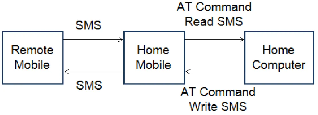
Figure 6.1: Block Diagram : AT Command Based Solution
However, after connecting, it normally binds the mobile with one of the virtual COM ports. So, the communication virtually becomes serial data communication behind the scene irrespective of the physical connection used. The commands pre-sented above can be tested in the computer Hyperterminal to verify the sequence of commands and their syntax. Only if the commands are verified, then it is suggested to port to programming codes.
6.4
Pseudo Code
Algorithm : ATCommandImplement
1. Perform initialization and setup
2. Poll the virtual COM port that is connected to the mobile 3. If there in an coming SMS get it
4. Authenticate the SMS and perform necessary actions 5. Go to step 2 and repeat the whole process
End
6.5
Pros and Cons
6.5.1 Pros
1. The communication is solely implemented using SMS protocol which is available at most of the places.
2. It doesn’t rely on the internet and web servers, which cuts down the overhead and the cost of the communication.
3. From the programming point of view, all the efforts are rendered for the com-puter and not the mobile, which makes the total implementation a relatively simple task.
4. There is no binding about the physical connection link that is used between the computers and mobile, which makes it more versatile and interoperable with data cables, Bluetooth and infrared.
6.5.2 Cons
1. AT command is somewhat device dependent. So, to permit devices from multiple vendors and multiple models, it may be necessary to alter the commands accord-ingly.
2. It is desired for a bidirectional communication that the communication can start from any of the two ends. But here the communication always starts with the command from the computer’s end.
Chapter 7
Demonstrating Prototype
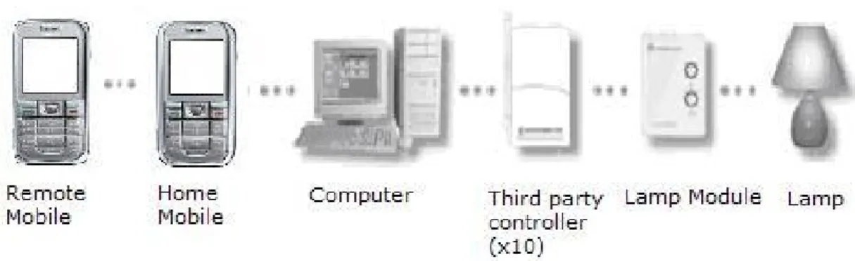
We implemented a prototype of the discussed remote system controlling project. Our implementation controls the home appliances of a home using mobile phones from anywhere. We also implemented various ways to communicate between the mobile phone and the computer. X10 Active Home Pro is used to take care of the real control mechanism once fed enough input to it. Using this set of devices, we concentrated on the communication aspect and came up with various solutions.
7.1
Brief Comparison of Different Alternative Solutions
The web based solution requires a web server hosting and internet connection at both the mobile phone and the home computer. Given that this specification is met, the home computer is responsible to forward the commands after formatting to the X10 controller. We do not stress one to adhere to this solution because the limiting factor of availability of internet is the obstacle to be called it truly remote.
The FBUS based solution incurs the extra coding complexity and also clumsy connection to the home mobile. The setup requires the home mobile to be stationed at home and connected to the computer. The controlling is done by the remote mobile. The unavailability of FBUS protocol details and strong dependency on Nokia mobile phones, it gets progressively harder to make robust programs.
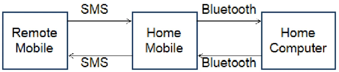
Bluetooth based solution is a very strong candidate to be judged the best among all. Bluetooth offers full bidirectional communication between the computer and the mobile. And also, a standard client-server based programming model eases the task. The controlling can be done from both the home and remote mobiles and also the home mobile is somewhat mobile in the sense that Bluetooth offers a small range of mobility. Also Bluetooth works for any mobile phone with Bluetooth API irrespective of the vendor. The only restricting factor with this solution is, it requires human intervention for custom made applications in the mobile for sending and receiving data to and from outside resources. Provided that, this step is avoidable, it seems very logical to make use of this solution.
We proposed the AT command based solution for its simplicity and ease of use. It doesn’t incur any extra cost and it’s available with all the mobile phones. The connection has no restrictions for the home mobile as it can be connected using any of the ways available like Bluetooth, Infrared and data cables. It also alleviates the necessity of any human intervention. The programming is concerned only with the computer and nothing about the home mobile, which makes the task simpler.
7.2
Description of the Prototype
The prototype implementation involves two mobile phones, one computer and X10 Active Home Pro system as hardware components. The software facilitating the whole communication is developed using programming languages Java Standard Edition (J2SE) and Micro Edition (J2ME) and also a C program is used from the Java using JNI (Java Native Interface).
7.2.1 Remote Mobile
The remote mobile is free to operate in either of the two ways. The preferred one is for the Java enabled mobile phones. We developed a J2ME application for the remote mobile. The application lets one to assign human friendly set of names instead of the default naming of the X10 modules. The user is free to use either the
assigned names or the X10 specific names using a simple graphical user interface from their mobiles. For the rest of the mobiles that doesn’t come with a support for Java the user is asked to send a Home Control Message to control the home appliances. The remote mobile is totally vendor independent and the capability of sending and receiving SMS is the only necessary requirement for it.
7.2.2 Home Mobile
The home mobile is connected to the computer using a standard data cable. The computer communicates with the mobile using AT command.
7.2.3 Home Computer
The computer in our prototype uses the AT command protocol to determine if a new Home Control Message is received in the home mobile. The prototype software is developed in windows based platform but can easily be migrated to other OS like Unix/Linux and so on. Upon recognizing and authenticating a home control mes-sage the computer makes a look up to the mapping between the human readable names and the X10 specific codes. Once the machine key corresponding to the X10 device is formed the message is sent to the specific USB port which connects to the X10 controller.