Abstract: Manoeuvrable robot commonly has become the focus of the latest heated issues especially in applications that involved disaster rescue, military missions and underwater or extra-terrestrial explorations. Currently, the manoeuvrable robot is controlled manually by the operator and it’s a wheeled type. It is used for rescue missions to transport people from disaster area to the safe zone. However, the robot is incapable of moving automatically, and it goes through terrain or landscape like swarm. Therefore, a suitable platform is required to transport or for other uses especially in dangerous mission. It is very difficult to estimate the movement of the robot to avoid obstacles and choose the alternative path. Hence, this research presents the point-to-point gait identification or path planning of the behavious of the robot to manuever autonomously on both on-land and underwater environment. For the optimization, the robot will travel from one specific point to another with the predefined position within optimized gait and fastest time by using Ant Colony Optimization (ACO) technique. The algorithm being compared, between Ant Colony Algorithm (ACO) and the Particle Swarm Optimisation (PSO) in terms of time and distance. The ACO been chosen because of the positive feedback for rapid discovery and able to use in dynamic applications for example adapts to changes like new distances. The performance of the algorithm showed that the execution time of ACO is more realistic. Hence, Matlab is used to determine the best cost extracted from the ACO with the pre-define of number of iteration and the number of ants. The laboratory-scaled prototype for amphibious vehicle was developed to test the design controlled with ACO technique where Global Positioning System (GPS) is used for the coordination of the robot and Magnetometer for the position of the robot. The robot prototype is able to move autonomously and optimized by the ant colony optimization with predefined position and terrain condition.
Keywords: ACO, Path; GPS; Amphibious; Manoeuvrable;
I. INTRODUCTION
Multiple highly manoeuvrable robots have become the focus of heated discussion lately, especially in applications involving disaster rescue, military missions and underwater or extra‐terrestrial explorations. The surroundings concerned are harsh and hazardous terrains, and predictably the malfunction rate is high. Thus, the development and analysis of a robust amphi-underwater is needed as a solution with the capability to maneuver on both land and underwater is of prime importance. One of the most important aspects of the legged robot is to optimise the executing patterns of leg-joint angles which is known as gaits. Synthesizing gaits by manual tuning control is a complex and time-consuming
Revised Manuscript Received on March 10, 2019.
M. S. M. Yusof, Department of Mechatronics, Faculty of Engineering, International Islamic University Malaysia, Kuala Lumpur, Malaysia (Email: [email protected])
S. F. Toha, Department of Mechatronics, Faculty of Engineering,
task which becomes even more challenging when the vehicle operates underwater. However, the mechanism presented in the literature are focusing on individual mechanism either on-land or underwater gait configuration. In fact, both mechanisms is tackled separately whereas in a typical application such as surveillance, both mechanism can be integrated and executed appropriately to fulfil bigger objectives in a better optimized relocate position as well as in faster completion time. When operating on both land and underwater any motion of the limbs applies forces to the robot. Efficient gait identification must therefore be modelled to mitigate these unwanted forces like shear, torque and rotational forces while meeting the desired gait properties. This research proposed automatic gait synthesis system for a hybrid amphi-underwater robot. The system utilizes an ant colony optimisation which provides randomization and attractiveness parameter adaptation during the iteration process. The resulting will improve significantly both maneuvering time but also optimizing total energy usage during operating cycle.
There are several different control methods can be used to assist the movement of the amphi-underwater vehicle which will varies the motion and speed control. In this research, motion control method is selected to be applied and studied. The motion of the motor will be affecting the movement of the leg. All the leg will be monitored and analysed to assist and control the speed of the vehicle. The research will be conducted in both software simulation and in experimental setup. In software simulation, the value and mathematical model of motor is employed to represent it in Matlab and Simulink platform. The research will be focusing on the application of Ant Colony Optimization (ACO) algorithms to tune the PID controller. While in experimental setup, the movement test is designed in the scale of the legged vehicle. The scaled down legged vehicle size is chosen in this study in order to reduce the complexity of the design from the real-life system also able to overcome obstacle such as fallen trees, swamp and others. The performance of the ACO-tuned controllers as able to follow the path planning and the fabrication of legged robot is the main scope of this research.
II. EXPERIMENTAL RESULTS
Most recently, several techniques have been proposed for mechanical design technique of behaviour models [1], [2]. They can be further categorized into several different types
Gait identification and optimisation for
amphi-underwater robot by using ant colony
algorithm
ROBOT BY USING ANT COLONY ALGORITHM according to whether an explicit model is built. Approaches
that the design and movement of the mechanism that developed according to the design structure that can cut down the simulation maintenance and reduce failure part [3]. Another design approach is a class of robotics legs that enable amphibious operation, both walking and swimming, for use on a class of hexapod robots [4]. In Figure 1 shows the robot equip with the six leg which can be used for walking on land and has flippers design which can swimming in water thus the thrust generated by leg and swimming flippers. The consideration of gait patterns on legged system can help to improve the speed and stability of the design yet easily to move at desired position [1].
Fig. 1: Tripod walking gait of the robot by using legs (Dey et al., 2013)
Another approach design is based on the serpentine, rectilinear, concertina and side winding movement which can conclude as snake movement on land and water [5] as example in Figure 2. The movement of the design is inspired by the animal and it shown a lot of difficulty when coming to the obstacle which is can slow down the speed and the movement cannot be predicted [6], [7].
Fig. 2: Snake-look robot known as ACM-III (Hirose & Yamada, 2009)
The design with the buoyancy system support is another approach for amphibious vehicle and use the wheel to move on land and retracted in water [2], [8]. The amphibious vehicle movement based on fuel battery cell which also use in Electric Vehicle (EV) use the hydraulic mechanical transmission inspired by traditional transmission for drive system [9]. Vehicle body design also affected the movement and give resistance especially in water [8].
2.1 Pattern of legged motions
High maneuverable turning gait is essential to improve the locomotion ability for multi-legged robots. From space exploration, catastrophe response to mine-sweeping, disaster management and extra-terrestrial surveillance, there are many applications for robots in situations where people would be endangered or cannot go [10]. Thus, robots may need to be used instead of humans in those kinds of mission. Legged robots have a wide range of applications and are used for many tasks that cannot be accomplished by wheeled ones.
The process of developing a pattern of legged motions to perform movements on both on-land and underwater environments are known as gait synthesis. Gait synthesis is difficult in part due to the large search space associated with the problem [11]. Using the traditional method, the optimal turning gait is a numerical and complex solution. Given a start position (state) and an end position (state) for the robot, the task of gait synthesis is to generate patterns of joint angles as a function of that time that move the robot between the two configurations.
Most commonly, legged robot gaits are designed and tuned by manual control mechanism. This approach, while quick to implement, has several drawbacks. First, moving the robot between two positions involves carefully manual tuning the pattern of individual leg joint angles to generate the intended motion. This can be very time consuming. Second, manual turning gaits does not scale well with the complexity of the robot and does not tolerate with its degrees-of-freedom (DOF) or with increases in environmental complexity [12].
In [13] used the term “fault-tolerant” to refer to their alternative gait approach for hexapod robots in which two legs were lifted in every step. More recently, [14] proposed an acheme for retaining the fault-tolerant gait proper of legged robots with certain leg failure while each joint in this robot’s leg system was assumed to be able to lock independent.
In 2014, NASA developed an eight-legged robot for planetary exploration, also studied and improved the problem of free gait generation and adaptability with reinforcement learning in normal conditions [15]. The mechanism presented in the literature are focusing on individual mechanism either on-land or underwater gait configuration. In fact, both mechanisms are tackled separately whereas in a typical application such as surveillance, both mechanisms can be integrated and executed appropriately to fulfil bigger objectives in a batter optimized relocate position as well as in faster completion time.
2.2 Crank rocker mechanism
The robot uses crank-rocker mechanism which is mean one of the links joint or connected to the fixed link which is oscillates while the other has a 360-degree rotation. Crank- rocker mechanism used in industrial, engineering and also agricultural machinery transmission is very extensive, and it
is important to have analytical data as to establish the relative equation of the input error (The calculations of reliability model for crank-rocker mechanism). This robot uses the mechanism which is crank-rocker is one of the adjustable mechanisms that capable of generating multiple paths with a changing in one or more in mechanism parameters by using the same hardware. The mechanism is divided into types of path generations which is point-to-point generation and continuous path generation. In the case of planar four bar mechanisms, there are at most nine parameters and one Boolean value which defines the mode of the linkage assembly [16] and in the point-to-point path generation, the coupler point can be made to pass exactly through at most nine precision points.
2.3 Underwater robot
Most of the industrial that has a common interest to the sea or water used underwater robot (UWR) as their main mechanism to do something underwater. UWR are used commonly for investigating environmental parameters under river, water quality checked, canals, welding, pick and place and seashores. In addition, the underwater robot also been used in solving marine gravimetry by provides new advanced technology for more precision measurements and mapping on local gravitational fields [17]. In the university level, underwater robot commonly constructed based on animal behaviour. Some of the robot will be mimicked animal like fish which is use fin as main mechanical and magnet-in-coil for the driven [18]. The underwater robot been research for the movement behaviour and use sensor to detect the gait characteristic. Under than that, spider also inspired students to make robot for the movement behaviour. Underwater robot also has been commonly used in many fields especially in subsea tasks, ranging ocean inspection or repair underwater structures related to the main power or oil industry [10]. Moreover, the robot needs to deal with the highly dynamical underwater environment which is represent in the form of ocean waves.
2.3.1 Bio-mimicry robot
In the Figure 3 shows that the assembly robot inspired by fish as to move in water. This robot designed by Berlinger which is use 3d printing with the ABS material [18]. The robot maneuver inside the water by using flapping mechanism which is driven by caudal/rear fin. The robot is designed to be passively move straight and stable along the path.
Fig. 3: The assembly fish robot with the sensor [18]
Another researcher already done with another design which also imitates the shape and the principle body of jellyfish [19]. In order to save the mineral resources, marine biological and energy, the body of the robot designed to look like animal. Moreover, this robot also been used as
oceanographers which is can be predicted the earthquakes, tsunamis and other natural disaster. This robot is divided into two parts which is umbrella and oral arm which is locate the power of the robot and gain the momentum through the extruding of seawater under the umbrella. The jellyfish in Figure 4 show the robot use propeller as a driven to move underwater.
Fig. 4: The structure of jellyfish body [19]
2.4 System optimization
2.4.1 Particle swarm optimization (PSO)
Metha heuristic algorithm or stochastic algorithm is known as particle swarm optimization that used for the optimization problems and globally used as evolutionary computation (Imran. M. et al., 2012). It was developed through simulation of a simplified social system and has been found to be robust in solving continuous nonlinear optimization problems [20]. By using this algorithm, the problems can be solved in a high- quality solution that help the user to get the answer with shorter calculation time and achieve stable convergence characteristic. This algorithm is started from the simulation of the bird flock that flying together in multi-dimensional space in order to search some optimum place, adjusting the movements and distances as to get the best result on finding the target.
The algorithm mimics a particle flying in the search space and moving towards the target. A particle will be depending on how much particle will be used. Each particle has their own velocity and position which are randomly initialized from start. Each particle will maintain its position as to be known as best position and global best position among all the particles. In this algorithm, a swarm of number individuals communicate either directly or indirectly with one another search direction which is called gradients. The algorithm is a simple but powerful search technique which divide into two type of approaches which is cognitive and social. Most of the application use social approaches as it can be known with each other’s position as to solve the problem.
2.4.2 Ant colony optimization (ACO)
Dorigo and colleagues [21] introduce The Ant Colony Optimization (ACO) as a general-purpose metaheuristic algorithm and a method for solving hard combinatorial optimization problems (COPs). This combinatorial problem
ROBOT BY USING ANT COLONY ALGORITHM concern on finding a grouping, ordering, or assignment of a
discrete set of objects which satisfies certain constrains [22]. This algorithm has been used to solve many combinatorial optimization problems such as in the optimization problem of the traveling salesman [23], data clustering and robotics.
The behaviour of ant colony inspiring this population-based technique which is the ant algorithm. The ACO algorithm have been inspired by the experimental based the observation of how the ant behaviour in selecting its path for food foraging between the nest and a source of food. A group of ant’s travels in randomly stochastic way along different path from nest to the food source. The ants will be deposited a pheromone along their way and for the ants which travel on the shortest path they will arrive back to the nest earlier. Consequently, the other ants will follow the shortest path due to high pheromone on that route. And after a certain time, it was observed that the ants quickly converged to the shortest path.
The research involving ACO algorithm can be seen in various fields such as in vehicle routing, biological system, image processing and scheduling and planning. In biological problem model, [24] applied ACO as a feature selection method in the high-dimensional datasets. For a vehicle routing problem, [25] proposed a multiple Ant Colony System for the system with time window constraint and under travel time uncertainty. Ant Colony System to optimize routes for recycling waste collection from households suing multi-compartment. Slightly different field which being explored using ACO algorithm is in the Mission Planning and Scheduling (MPS) for disaster monitoring constellation [26]. Literature shows the limitless potential of ACO to be applied in many complex system and problems give an opportunity to investigate its feasibility to be applied in this research.
III. SIMULATION AND RESULT 3.1 Mechanical fabrication
The design of this controller is simple, and this model has been used for the control system design. This robot stabilization divided into two control which is robot positioning and orientation. The robot positioning control must assure the achievement of a desired position which can be calculated with the including of the GPS coordinate (x_ref, y_ref), regardless of the robot orientation. While the robot orientation control must assure the achievement of the desired position and orientation. To simplify the block diagram, Figure 5 show the input was from algorithm that control the speed of the motor. The changes of proportional able to change the directional of the robot. When the algorithm tune on the proportional will change the speed of the motor and follow the desired direction of the point.
∑ Error P kp e(t) Motor
Target angle Algorithm
tuned
Fig. 5: Block diagram for control system
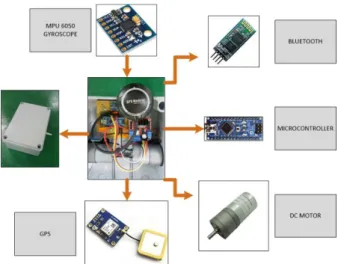
The design of the robot is the combination of the 3D prototyping and acrylic to as a mechanism of the robot. In order to visualize the movement of the robot, it shows that the movement of the leg is drive by the motor which is transfer the energy through the rotation of gear. All the leg and the gear are made up from 3D printing. The box is contained the electrical component which is microcontroller, motor and others as shown in Figure 6. All the components will be communicating each other for better movement.
Fig. 6: Electrical Component of the robot
3.2 Simulink model simulation
This section shows the results of various point of cities for ACO. All the points were initialised and randomly at certain area. In the Figure 7 show all the point from 5 until 50 points with the fixed position of initial at (0,0) and the final position (100,100). These graphs show the improvement of path from the 5 until 50 points which the graph plot smoother at the 50 points. All the data have a fixed 40 ants and with the 100 of iterations. From the fixed shape it turns to become more circular shape which is able to move and make the path planning.
(a) 5-point of best cities (b) 10-point of best cities
(c) 15-point of best cities
(d) 20-point of best cities
(e) 25-point of best cities
(f) 30-point of best cities
(g) 35-point of best
cities (h) 40-point of best cities
(i) 45-point of best cities
(j) 50-point of best cities Fig. 7: The best point among the cities
For the convergence graph of best cost over iteration, the result is shown in Figure 8. it is apparently showing the convergence graph of the best cost for various cities from 5 until 50 with the ten times trial for each part. The cities of 50 show that it starts with the higher cost which is 1114.1959 and it finish at 308.4232 which show the iteration at 79 out of 100. This is the graph convergence for all the best cities and run at 100 iterations only. From the graph, it shows that the cities with point has a constant cost which is start at first iteration at the value of 245.694. In order to establish repeatability, this simulation was run ten times independently. All the simulations were carried out on a Laptop (Intel ® Core (TM) i5-4210H CPU with 2.90GHz).
Fig. 8: The best cost convergence for various cities from 5 until 50 points
3.3 Autonomous maneuver
In this part, the tuned of ACO algorithm is applied in the robot controller. The parameters of the distance between point is used in the previous calculation. Moreover, the current and power being monitored since there is slope and
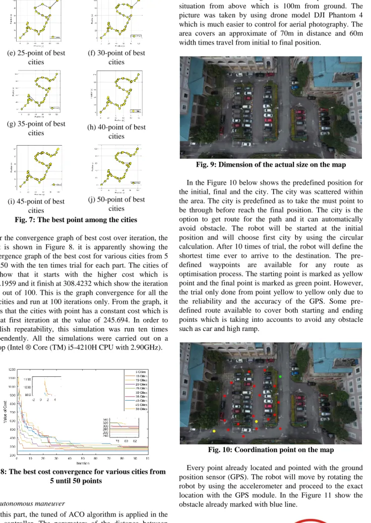
terrain surface. In the Figure 9 show the picture of real situation from above which is 100m from ground. The picture was taken by using drone model DJI Phantom 4 which is much easier to control for aerial photography. The area covers an approximate of 70m in distance and 60m width times travel from initial to final position.
Fig. 9: Dimension of the actual size on the map
In the Figure 10 below shows the predefined position for the initial, final and the city. The city was scattered within the area. The city is predefined as to take the must point to be through before reach the final position. The city is the option to get route for the path and it can automatically avoid obstacle. The robot will be started at the initial position and will choose first city by using the circular calculation. After 10 times of trial, the robot will define the shortest time ever to arrive to the destination. The pre-defined waypoints are available for any route as optimisation process. The starting point is marked as yellow point and the final point is marked as green point. However, the trial only done from point yellow to yellow only due to the reliability and the accuracy of the GPS. Some pre-defined route available to cover both starting and ending points which is taking into accounts to avoid any obstacle such as car and high ramp.
Fig. 10: Coordination point on the map
Every point already located and pointed with the ground position sensor (GPS). The robot will move by rotating the robot by using the accelerometer and proceed to the exact location with the GPS module. In the Figure 11 show the obstacle already marked with blue line.
ROBOT BY USING ANT COLONY ALGORITHM
Fig. 11: Obstacle detection on the map
In this part, the movement of the robot to the destination (yellow dot) done with 10 times of trials. This is important to determine the error of autonomous robot to arrive at destination. The initial position has been pre-defined at the (3.253497, 101.732126) and the final position at (3.253528, 101.732375). The distance was 20m and the ground is flat and there is only some obstacle that able to overcome it. Time of Error=Autonomous (trials)- Autonomous (fastest) (1)
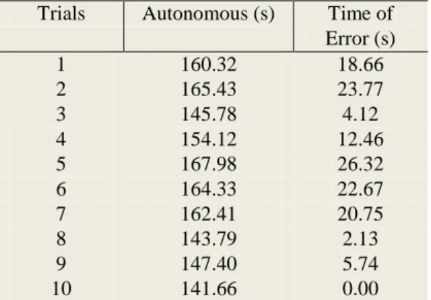
From the Equation (1), the time of error calculated and recorded in the below Table 1. the experiment done with the 10 time of trials move from predefined location to predefined position with autonomous configuration. The time of error calculated and show that biggest error from the 10 trials was 26.32s. In this part, the movement of the robot to the destination (yellow dot) done with 10 times of trials. This is important to determine the error of autonomous robot to arrive at destination. The initial position has been pre-defined at the (3.253497, 101.732126) and the final position at (3.253528, 101.732375). The distance was 20m and the ground is flat and there is only some obstacle that able to overcome it.
Table 1: Trials of maneuverable from point 1 to point 2
Trials Autonomous (s) Time of
Error (s) 1 160.32 18.66 2 165.43 23.77 3 145.78 4.12 4 154.12 12.46 5 167.98 26.32 6 164.33 22.67 7 162.41 20.75 8 143.79 2.13 9 147.40 5.74 10 141.66 0.00
In the Figure 12 show the bar graph of the time error with 10 trials. The graph shows that at the trial of 10 get the fastest time to reach final destination. The different of time value is because of the surface of the road, reliability of the robot ang the accuracy of the GPS coordinate.
Fig. 12: Graph between time of arrival from point A to B and number of trials
The algorithm seems stable and the difference is due to others factor like condition of the road. The consideration of unstable GPS coordination also should be taken, and the movement take time to get the actual position.
IV. CONCLUSION AND RECOMMENDATION
The proposed design intends to choose either the legged robot able to move or controlled just like wheeled robot. During the experiment, all the parameters variations and disturbance been recorded as to get optimum performance including the time taken to the targeted place. All the obstacles, routes and time is considered in controlled in order to get best results. The powerful optimal control is important to overcome the obstacle, space limitation, and the fastest route towards destination. The Ant Colony Optimisation is used as main algorithm to control the movement of the robot. This ACO shows the best result as practical algorithms in controller, yet, it can be used in actual systems. The control study on the ACO algorithms in TSP was done for the time consumption for the robot move from cities to the target position. ACO algorithms are applied in the system as the tuning mechanism of the PID controller. All the algorithms parameters been tested in the Matlab by giving the predefined position to the system. It is found that by using ACO is simpler and fast than PSO. The tuned parameters values later being investigated with the implementation of ACO to the robot system. Results show that the tuned parameters can help to reduce time taken for the robot to the target thus consume less energy taken of the robot to the destination. This research also provides the comprehensive formula to determine the actual parameters for the path by using Matlab. The lab-scale prototype was successfully developed to test the ACO controller. As stated above, most of the research use PSO algorithms as the main controller. They focus on the TSP for the wheeled robot and different strategy is applied. Based on the result, ACO algorithms delivers a robust performance more than PSO algorithms. The movement and control are simpler and offer a smooth movement of the robot.
ACKNOWLEDGEMENT
The author would like to acknowledge financial assistance from the International Islamic University Malaysia under the FRGS Grant FRGS17-031-0597: Gait Identification Modelling for a hybrid amphi-underwater robot with exponential momentum ant colony algorithm.
REFERENCES
1. German A and Jenkin M (2009), Gait synthesis for legged underwater vehicles, Proc. 5th Int. Conf. Auton. Auton. Syst. ICAS, pp. 189–194.
2. Guixia S & Youqun Z (2008), The design of wheel retraction function of amphibious vehicle, IEEE Veh. Power Propuls. Conf. VPPC, pp. 7–10.
3. Zheng S, Ye Z, Yang Z & Han J (2012), The special amphibious vehicle driving simulator design and development, Spring World Congr. Eng. Technol. SCET., pp. 6–9.
4. Dey BB, Manjanna S & Dudek G (2013), Ninja legs: Amphibious one degree of freedom robotic legs, IEEE Int. Conf. Intell. Robot. Syst., pp. 5622–5628.
5. Hirose S & Yamada H (2009), Snake-like robots: Machine design of biologically inspired robots, IEEE Robot. Autom. Mag.
16 (1), 88–98.
6. Holland O (2013), The First Biologically Inspired Robots,
Robotica 21 (4), S0263574703004971.
7. Xie X, Gao F, Huang C & Zeng W (2017), Design and development of a new transformable wheel used in amphibious all-terrain vehicles (A-ATV), J. Terramechanics 69, 45–61. 8. Hassan MZ, Razali MR & Halid MS (2013), Design and
Development of Amphibious Hybrid Vehicle Body Structure,
Int. J. Sci. Res.. 2 (5), 220–223.
9. Sheng WG, Fu WZ, Xun LC & Lu W (2015), Research on design of electric-drive scheme for amphibious electric vehicle with fuel cell battery, 8th Int. Symp. Comput. Intell. Des. Res. 10. Guo X, Ma S, Li B, Wang B & Wang Y (2015), Optimal turning
gait for a three-link underwater robot, 5th Annu. IEEE Int. Conf. Cyber Technol. Autom. Control Intell. Syst. June, vol. 5, pp. 1321–1326.
11. Lingling C, Yang P, Liu Z, Chen H & Guo X (2007), “Gait Optimization of Biped Robot Based on Mix-encoding Genetic Algorithm, 2nd IEEE Conf. Ind. Electron. Appl., pp. 1623–1626. 12. Sanfilippo F, Azpiazu J, Marafioti G & Transeth AA (2016), Perception-Driven Obstacle-Aided Locomotion for Snake Robots, 14th Int. Conf. Control. Autom. Robot. Vis., pp. 1–7. 13. Chu SK & Pang GK (2002), Comparison Between Different
Model of Hexapod Robot in Fault-Tolerant Gait, IEEE Trans. Syst. MAN, Cybern. A Syst. HUMAN, vol. 32, no. 6, pp. 752– 756.
14. Mostafa K, Tsai C & Her I (2010), Alternative Gaits for Multiped Robots with Leg Failures To Retain Maneuverability,
Int. J. Adv. Robot. Syst..7 (4), 31–38.
15. Spenneberg D (2004), Stability of Walking in a Multilegged Robot Suffering Leg Loss, IEEE Int. Conf. Robot. Autom., pp. 2159–2164.
16. Kamat G, Hoshing G, Pawar A & Lokhande A (2014), Synthesis and Analysis of Adjustable Planar Four-bar Mechanism, Int. J. Adv. Mech. Eng. 4 (3), 263–268.
17. Kiselev LV, Medvedev AV, Kostousov VB & Tarkhanov AE (2017), Autonomous underwater robot as an ideal platform for marine gravity surveys, 24th Saint Petersbg. Int. Conf. Integr. Navig. Syst. ICINS.
18. Berlinger F, Dusek J, Gauci M & Nagpal R (2017), Robust Maneuverability of a Miniature, Low-Cost Underwater Robot Using Multiple Fin Actuation, IEEE Robot. Autom. Lett., vol. 3, no. 1, pp. 140–147.
19. Lingshuai M, Yang L, Haitao G, Hongli X & Lingbo G (2016), A new type of small underwater robot for small scale ocean observation, 6th Annu. IEEE Int. Conf. Cyber Technol. Autom. Control Intell. Syst. IEEE-CYBER, pp. 152–156.
20. Rajinikanth V & Latha K (2012), Modeling, Analysis, and Intelligent Controller Tuning for a Bioreactor: A Simulation Study, Int. Sch. Res. Netw. Chem. Eng. 2012, 1–15.
21. Dorigo M, Maniezzo V & Colorni A (1996), The Ant System : Optimization by a colony of cooperating agents, IEEE Trans. Syst. Man, Cybern. B, vol. 26, no. 1, pp. 1–13.
22. Hoos HH (2003), Stochastic Search Algorithms, 3rd Int. Jt. Conf. Artif. Intell., vol. 3, pp. 17–24.
23. Cheng C & Mao C (2007), A modified ant colony system for solving the travelling salesman problem with time windows,
Math. Comput. Model., vol. 46, pp. 1225–1235.
24. Barbosa HJC (2013), Ant Colony Optimization - Techniques And Applications. Rijeka, Croatia.
25. Toklu NE, Gambardella LM & Montemanni R (2014), A Multiple Ant Colony System for a Vehicle Routing Problem with Time Windows and Uncertain Travel Times, J. Traffic Logist. Eng. 2 (1), 52–58.
26. Donati A, Iacopino C & Palmer P (2013), EO Constellation MPS based on ant colony optimization algorithms, 6th Int. Conf. Recent Adv. Sp. Technol., vol. 6, pp. 159–164.

![Fig. 3: The assembly fish robot with the sensor [18]](https://thumb-us.123doks.com/thumbv2/123dok_us/1167383.2656560/3.893.476.804.222.404/fig-assembly-fish-robot-sensor.webp)