P
ROGRAMMING A
S
ELF
-D
RIVING
C
AR
O
NISHIMH
ASDAKS
UPERVISOR:
A
BUM
OHAMMADH
AMMADA
LID
EPARTMENT OFC
OMPUTERS
CIENCE&
E
NGINEERINGS
CHOOL OFE
NGINEERING&
C
OMPUTERS
CIENCEBRAC
U
NIVERSITYM
OHAKHALI,
D
HAKA-1212
P
ROGRAMMING A
S
ELF
-D
RIVING
C
AR
A Thesis submitted in
partial fulfillment of the requirements for the degree of
Bachelor of Science in Computer Science & Engineering of
BRAC University
By
Onishim Hasdak (09201003)
Supervisor:
Abu Mohammad Hammad Ali
August 2015
© 2015 Onishim Hasdak All Rights Reserved
iii
D
ECLARATIONThis is to certify that the research work titled “Programming a Self-Driving Car” is submitted by Onishim Hasdak (ID-09201003) to the Department of Computer Science & Engineering, BRAC University in partial fulfillment of the requirements for the degree of Bachelor of Science in Computer Science and Engineering. The contents of this thesis have not been submitted elsewhere for the award of any degree or any other publication. I hereby declare that this thesis is my original work based on the results I found. The materials of work found by other researchers and sources are properly acknowledged and mentioned by reference. I carried out my work under the supervision of Abu Mohammad Hammad Ali.
Dated: 23 August 2015
Signature of Supervisor
_____________________________ Abu Mohammad Hammad Ali Senior Lecturer
Department of Computer Science &Engineering School of Engineering & Computer Science BRAC University
Signature of Author
_____________________________ Onishim Hasdak (09201003)
BRAC UNIVERSITY
FINAL READING APPROVAL
Thesis Title: Programming a Self-Driving Car Date of Submission: 23rd of August, 2015
The final form of the thesis report is read and approved by Abu Mohammad Hammad Ali. Its format, citations, and bibliographic style are consistent and acceptable. Its illustrative materials including figures, tables, and charts are in place. The final manuscript is satisfactory and is ready for submission to the Department of Computer Science & Engineering, School of Engineering and Computer Science, BRAC University.
Supervisor
__________________________________ Abu Mohammad Hammad Ali Senior Lecturer Department of Computer Science and Engineering School of Engineering & Computer Science BRAC University
A
CKNOWLEDGMENTI am grateful to my thesis supervisor Abu Mohammad Hammad Ali, Senior Lecturer, Department of Computer Science & Engineering, for his inspiration, idea, guidance and overall suggestions to improve this work. He has offered us understanding and support at all stages of our work. His practical suggestions kept us rooted to reality, and helped us to complete our work on time.
A
BSTRACTSelf-driving cars are autonomous vehicles that can drive through traffic all by themselves. As unbelievable or far-fetched as it may sound, it may just be the greatest technological revolution of the near future. It involves the use of Mechatronics and Artificial Intelligence (AI) to control the vehicle, thereby taking the responsibilities of the driver, providing a more manageable control over it. And a swarm of autonomous vehicles could just be the solution to our traffic problems; no traffic jam, no road accidents, no delayed journey; life would be so much easier. As part of my thesis, I am programming a self-driving miniature robot car, as the unit of the swarm of self-driving cars. There are several technologies that can be used to develop these autonomous vehicles- laser, lidar, radar, ultrasonic sensors, GPS, image processing, computer vision, machine vision etc. Since I am programming for a miniature size robot car, I have chosen to use smaller and easily available technologies. The processing unit of my robotic car is an Android Phone, which is already equipped with GPS, Gyroscope and other sensors. Other devices I am using are Raspberry Pi & Sonar sensors that work together to detect obstacles. My goal is to program the car to be able to navigate its way from one point to another on a given driving environment avoiding any obstacle on the way. In the future I would like to implement my car’s AI on a swarm of robot cars, having them operate on the same environment and follow real life traffic rules and guidelines, and developing swarm intelligence.
Index Terms: artificial intelligence, autonomous vehicle, global positioning system (GPS), path-finding, Raspberry-pi, self-driven car, ultrasonic sensor
C
ONTENTSCHAPTER 1 ... 1
1.1 Introduction ... 1
CHAPTER 2 ... 3
2.1 Background and History ... 3
2.2 Literature Review & Other Study ... 4
2.2.1 Stanley: The Robot that Won the DARPA Grand Challenge ... 5
2.1.1 Google Self-driving car project ... 8
2.1.2 Google Maps ... 11
2.2 Different Technologies Used in Self-driving Cars ... 12
CHAPTER 3 ... 21
3.1 Approach Followed ... 21
3.2 Software Components ... 22
3.3 Hardware Components... 25
CHAPTER 4 ... 32
4.1 Google Maps API V2 ... 32
4.2 Legs... 32 4.3 Decimal degree ... 33 CHAPTER 5 ... 36 4.1 Development Phase ... 36 4.2 System Diagram ... 41 4.3 Processing Pipeline ... 42 4.4 How it works: ... 42 4.5 Steps: ... 43
4.6 The Obstacle Detection System ... 49
4.7 Algorithm ... 52
5.1 Output and Result ... 54
CHAPTER 6 ... 58
6.1 Conclusion ... 58
6.2 Future Work ... 59
REFERENCES ... 60
1
CHAPTER 1
1.1
Introduction
A self-driving car, also known as a driverless car, driver-free car, autonomous car, or robot car is an autonomous vehicle capable of fulfilling the human transportation capabilities of a traditional car. As an autonomous vehicle, it is capable of sensing its environment and navigating without human input. Robotic cars exist mainly as prototypes and demonstration systems. Autonomous vehicles sense their surroundings with such techniques as radar, lidar, sonar, GPS, and computer vision. Advanced control systems interpret sensory information to identify appropriate navigation paths, as well as obstacles and relevant signage. Some autonomous vehicles update their maps based on sensory input, allowing the vehicles to keep track of their position even when conditions change or when they enter uncharted environments [1].
I always dreamed of having an artificially intelligent car. It probably spur from the 90’s TV series “Team Knight Rider”, but the later TV series “Knight Rider” (2008-2009) just gave a spark to the dream. Being an Engineering student, I decided to make my own. So, I chose to build a self-driving car as my thesis project.
2
The goal of this thesis is to design a self-driving car that would be able to drive from a start location to a goal location on a normal driving environment. To achieve the goal a small robot car would locate its current position on a provided map, find the path to the destination and drive along the path avoiding any obstacle along the way.
3
CHAPTER 2
2.1
Background and History
There has been research and development on the technology of automatic driven vehicles from the early nineteen hundreds. Some quasi-autonomous demonstration systems date back to the 1920s and the 1930s. Since the 1980s, when Mercedes-Benz and Bundeswehr University Munich built a driverless car through the EUREKA Prometheus Project, significant advances have been made in both technology and legislation relevant to autonomous cars. Numerous major companies and research organizations have developed working prototype autonomous vehicles, including Mercedes-Benz, General Motors, Continental Automotive Systems, Autoliv Inc., Bosch, Nissan, Toyota, Audi, Volvo, Vislab from University of Parma, Oxford University and Google. In 2010, four electric autonomous vans successfully drove 8000 miles from Italy to China. The vehicles were developed in a research project backed by European Union funding, by Vislab of the University Of Parma, Italy. In July 2013 Vislab world premiered BRAiVE, a vehicle that moved autonomously on a mixed traffic route open to public traffic. As of 2013, four U.S. states have passed laws permitting autonomous cars: Nevada, Florida, California, and Michigan. In Europe, cities in Belgium, France, Italy and the UK are planning to operate transport systems for driverless cars. Also
4
in Europe, Germany, Netherlands and Spain have allowed testing robotic cars in traffic. Finland is planning on passing a law before year 2015 [2].
In the United States, the National Highway Traffic Safety Administration (NHTSA) has established an official classification system [3]:
Level 0: The driver completely controls the vehicle at all times.
Level 1: Individual vehicle controls are automated, such as electronic stability control or automatic braking.
Level 2: At least two controls can be automated in unison, such as adaptive cruise control in combination with lane keeping.
Level 3: The driver can fully cede control of all safety-critical functions in certain conditions. The car senses when conditions require the driver to retake control and provides a "sufficiently comfortable transition time" for the driver to do so.
Level 4: The vehicle performs all safety-critical functions for the entire trip, with the driver not expected to control the vehicle at any time. As this vehicle would control all functions from start to stop, including all parking functions, it could include unoccupied cars.
2.2
Literature Review & Other Study
There has been a lot of work going on in designing autonomous navigation system. Almost all major car companies are working on self-driving cars. Among them Google’s self-driving car seems to be under the spotlight. My work is mostly inspired from the work of Sebastian Thrun on both the Google self-driving car and the prior Stanley project that he started in Stanford.
5
Thrun was able to continue his research under a secret facility of Google called Google [x] [5]. Though most of the details remain a secret, he has put up the theory of making autonomous cars in various publications as well as an online Artificial Intelligence course he has designed.
One other topic worth looking into is the Google Maps. It is a popular, if not the most popular, mapping system, that can be used for navigation almost all over the world. It can search the best route to a place in less than a fraction of a second. Which is impressive, because even the best algorithms can’t do that in an instant. However pre-traversed map with monotonic heuristics can be used to improve these search algorithms, A* for instance. That could be the key to Google Maps secret. Findings from studying these topics are discussed below.
2.2.1
Stanley: The Robot that Won the DARPA Grand Challenge
Stanley is the robot car that won the 2005 DARPA Grand Challenge. Stanley was developed for high-speed desert driving without manual intervention. The Grand Challenge was launched by the Defense Advanced Research Projects Agency (DARPA) in 2003 to spur innovation in unmanned ground vehicle navigation. The goal of the Challenge was to develop an autonomous robot capable of traversing unrehearsed off-road terrain.
The main technological challenge in the development of Stanley was to build a highly reliable system, capable of driving at relatively high speeds through diverse and unstructured off-road environments, and to do all this with high precision. These challenges let to a number of advancements in the field of autonomous navigation.
The project was led by Associate Professor Sebastian Thrun, director of the Stanford Artificial Intelligence Lab. Later he went on to work with Google on their Self-driving car project.
6
Most of my work is inspired from the work done by Thrun in autonomous navigation systems. The software system of Stanley in particular sets a standard for the development of any self-driving.
Figure 1. Stanley, the self-driving car developed by Stanford University
Construction: Stanley used five roof mounted Sick AG LIDAR units to percept the environment and build a 3-D map, along with position sensing GPS system. An internal guidance system utilizing gyroscopes and accelerometers monitored the orientation of the vehicle. Additional guidance data was provided by a video camera used to observe driving conditions out to eighty meters and to ensure room enough for acceleration. For long-range detection of large obstacles, Stanley’s roof rack also holds two 24 GHz RADAR sensors, supplied by Smart Microwave Sensors. Both RADAR sensors cover the frontal area up to 200 m, with a coverage angle in azimuth of about 20°. Six Pentium M computers located in the trunk were responsible for all the processing.
7
Processing Pipeline: The system is broken down into six layers:
1. Sensor Interface Layer: This layer comprises a number of software modules concerned with receiving and time stamping all sensor data.
2. Perception Layer: In this layer, sensor data are mapped into internal models. The primary module in this layer is the Unscented Kalman Filter (UKF) vehicle state estimator, which determines the vehicle’s coordinates, orientation and velocity. Based on laser, camera and radar system modules a 2D environment map is constructed.
3. Control Layer: The control layer is responsible for regulating the steering, throttle, and break response of the vehicle.
4. Vehicle interface Layer: It contains all interfaces to the vehicle’s brakes, throttle and steering wheel. It also features the interface to the vehicle’s server, a circuit that regulates the physical power to many of the system components.
5. User Interface Layer: The user interface comprises the remote E-stop and touch-screen module for starting up the software.
6. Global Service Layer: This layer provides a number of basic services for all software modules. A centralized parameter server maintains a database of all vehicle parameters and updates them in a consistent manner. The physical power of individual system components is regulated by the power server.
Vehicle State Estimation: Estimating vehicle state is a key prerequisite for precision driving. An Unscented Kalman Filter (Julier & Uhlmann, 1997) is used to estimate these quantities. The UKF incorporates observations from the GPS, the CPS compass, the inertial measurement unit (IMU), and the wheel encoders. The absolute position and velocity measurements achieved from GPS are both incorporated into the UKF. While GPS is available, the UKF uses only a “weak”
8
model. This model corresponds to a moving mass that can move in any direction. The UKF places no constrain on the direction of the velocity vector relative to the vehicle’s orientation. However, this model performs poorly during GPS outages, as the position of the vehicle relies strongly on the accuracy of the IMU’s accelerometers. So a more restrictive UKF motion model is used. This model constrains the vehicle to only move the direction it is pointed. The integration of orientation coupled with wheel velocities for computing the position, is able to maintain accurate pose for up to 2 min while GPS is not available [6].
2.1.1
Google Self-driving car project
The Google Self-Driving Car is a project that involves developing technology for autonomous cars. Google Engineer Sebastian Thrun, former director of the Stanford Artificial Intelligence Laboratory, launched the company’s driverless car project at Google’s secret facility called Google[x]. It is currently being led by Chris Urmson. Stanley, the robotic vehicle created by Thrun’s team at Stanford, won the 2005 DARPA Grand Challenge. Google’s self-driving car project was the perfect platform for Thrun to continue his work on autonomous navigation systems.
9
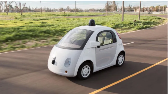
Figure 2. Google’s fully Self-Driving Car design introduced in May 2014
The state of Nevada was the first to pass a law on June 29, 2011, permitting the operation of autonomous cars in Nevada, which went into effect on March 1, 2012. The Nevada Department of Motor Vehicles issued the first license for an autonomous car in May 2012, to a Toyota Prius modified with Google's experimental driverless technology. Florida and California in 2012 and Michigan in 2013 were the next to allow testing of driverless cars in public roads.
In May 2014, Google presented a new concept for their driverless car that had neither a steering wheel nor pedals. In December of that year they unveiled a fully functioning prototype. Google plans to make these cars available to public by 2020.
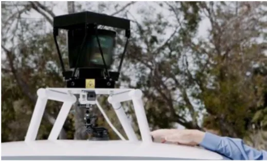
Technology: Google’s robotic cars have about $150,000 in equipment including a LIDAR system that itself costs $70,000. The Velodyne 64-beam laser range finder mounted on top
10
allows the vehicle to generate a detailed 3D map of its environment. The car takes these generated maps and combines them with high-resolution maps of the world, producing different types of data models that are then used for driving itself. Some of these computations are performed on remote computer farms, in addition to on-board systems.
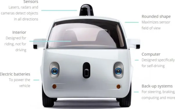
Figure 3. Features of Google Self-Driving Car
Limitations: As of August 28, 2014 the latest prototype has not been tested in heavy rain or snow due to safety concerns. The car still relies primarily on pre-programmed route data; they do not obey temporary traffic signals, and in some situations, revert to a slower “extra cautious” mode in complex unmapped intersections. The lidar technology cannot spot some potholes or
11
discern when humans, such as a police officer, are signaling the car to stop. But Google is having these issues fixed by 2020 [5].
2.1.2
Google Maps
Google Maps is a web mapping service developed by Google. It offers satellite imagery, street maps, 360° panoramic views of streets (Street View), real-time traffic conditions (Google Traffic), and route planning for traveling by foot, car, bicycle, or public transportation.
Google Maps started as a C++ desktop program designed by two Danish brothers, Lars and Jens Eilstrup Rasmussen at the Sydney-based company “Where 2 Technologies”. In October 2004, the company was acquired by Google, which converted it into a web application that was launched shortly thereafter in February 2005 [7].
Automatically finding routes quickly is a hard problem -- especially at a global scale (there are several hundred million road segments worldwide). Even if a routing program is needed to
only look at 10% of the map and only examine each segment for a microsecond, it would take tens of seconds to compute a path. Route-finding has to be done automatically because it would be impossibly time-consuming to compute the best routes between all pairs of locations by hand.
Barry Brumitt, a software engineer at Google, posted in the Google Official Blog about “The road to better path-finding”. According to his statement, a small group of engineers, of which he was a part, created the Google Maps route-finding project in Kirkland, WA with the hope of building a world-class system for route-finding, “We started with the geographic data sets already in use by other groups at Google. Then we designed, built, tested, and deployed a complete route-finding solution in under 12 months.”
12
The new route-finding system is hundreds of times faster: it can find and describe a cross-continental shortest path in well under a second; and shortest paths can be found proportionately faster. It took 10 months of hard work and thousands of MapReduce passes to achieve this kind of performance. MapReduce is a programming model and an associated implementation for processing and generating large data sets. The implementation of MapReduce runs on a large cluster of commodity machines and is highly scalable: a typical MapReduce computation processes many terabytes of data on thousands of machines [8].
So Google actually uses pre-computed solutions to provide the path finding results of Google Maps; the pre-computation itself is done on a large cluster of machines.
Despite how Google Maps provides the best route for a query, the shortest path algorithms like- Dijakstra’s algorithm and the modifications of it are the key behind it. One of the superior choices would be the A* algorithm, which is basically an extension of the Dijakstra’s algorithm. A* achieves better time performance by using heuristics.
2.2
Different Technologies Used in Self-driving Cars
Among the different approaches and techniques followed in the prior and ongoing researches found, components like the - laser, lidar, radar, GPS, image processing, computer vision, machine vision etc. are common . An automated car uses a combination of sensors and software to locate itself in the real world combined with highly accurate digital maps. A GPS is used, just like the satellite navigation systems in most cars, to get a rough location of the car, at which point radar, lasers and cameras take over to monitor the world around the car, 360-degrees.
13
The software can recognize objects, people, cars, road marking, signs and traffic lights, obeying the rules of the road and allowing for multiple unpredictable hazards, including cyclists. It can even detect road works and safely navigate around them.
i) Laser: A laser is a device that emits light through a process of optical amplification based on the stimulated emission of electromagnetic radiation. The term "laser" originated as an acronym for light amplification by stimulated emission of radiation. The new system, developed by researchers at the University of California, Berkeley, can remotely sense objects across distances as long as 30 feet, 10 times farther than what could be done with comparable current low-power laser systems. With further development, the technology could be used to make smaller, cheaper 3-D imaging systems that offer exceptional range for use in self-driving cars [9].
14
ii) Lidar: Lidar (also writtenLIDAR, LiDAR orLADAR) is a remote sensing technology that measures distance by illuminating a target with a laser and analyzing the reflected light. The term lidar was actually created as aportmanteau of "light" and "radar". It is popularly used as a technology to make high-resolution maps, with applications in geomatics, archaeology, geography, geology, geomorphology, seismology, forestry, remote sensing, atmospheric physics, airborne laser swath mapping (ALSM), laser altimetry, and contour mapping.
General Description: Lidar uses ultraviolet, visible or near infrared light to image objects. It can target a wide range of materials, including nonmetallic objects, rocks, rain, chemical compounds, aerosols, clouds and even single molecules. Anarrow laser-beam can map physical features with very high resolutions.
NASA has identified lidar as a key technology for enabling autonomous precision safe landing of future robotic and crewed lunar-landing vehicles.
Wavelengths of lidar vary from 10 micrometers to approximately 250nm (UV). The backscattering property of light is the key to its functionality. Different types of scattering are used for different lidar applications: most commonly Rayleigh scattering, Mie scattering, Raman scattering, and fluorescence. Suitable combinations of wavelengths can allow for remote mapping of atmospheric contents by identifying wavelength-dependent changes in the intensity of the returned signal.
Design: In general there are two kinds of lidar detection schemes:
15
Coherent detection: Coherent systems generally use Optical heterodyne detection, which, being more sensitive than direct detection, allows them to operate at a much lower power but at the expense of more complex transceiver requirements. This is best for doppler, or phase sensitive measurements.
In both kinds of lidar, there are two types of pulse models:
Micropulse lidar systems: Micropulse systems have developed as a result of the ever increasing amount of computer power available combined with advances in laser technology. They use considerably less energy in the laser, typically on the order of one microjoule, and are often "eye-safe," meaning they can be used without safety precautions.
High energy systems: High-power systems are common in atmospheric research, where they are widely used for measuring many atmospheric parameters: the height, layering and densities of clouds, cloud particle properties, temperature, pressure, wind, humidity, trace gas concentration.
There are several major components to a lidar system:
Laser — 600–1000 nm lasers are most common for non-scientific applications. They are inexpensive, but since they can be focused and easily absorbed by the eye, the maximum power is limited by the need to make them eye-safe. Eye-safety is often a requirement for most applications. A common alternative, 1550 nm lasers, are eye-safe at much higher power levels since this wavelength is not focused by the eye, but the detector technology is less advanced and so these wavelengths are generally used
16
at longer ranges and lower accuracies. They are also used for military applications as 1550 nm is not visible in night vision goggles, unlike the shorter 1000 nm infrared laser. Airborne topographic mapping lidars generally use 1064 nm diode pumped YAG lasers, while bathymetric systems generally use 532 nm frequency doubled diode pumped YAG lasers because 532 nm penetrates water with much less attenuation than does 1064 nm. Laser settings include the laser repetition rate, which controls the data collection speed. Pulse length is generally an attribute of the laser cavity length, the number of passes required through the gain material (YAG, YLF, etc.), and Q-switch speed. Better target resolution is achieved with shorter pulses, provided the lidar receiver detectors and electronics have sufficient bandwidth.
Scanner and optics — How fast images can be developed is also affected by the speed at which they are scanned. There are several options to scan the azimuth and elevation, including dual oscillating plane mirrors, a combination with a polygon mirror, a dual axis scanner (see Laser scanning). Optic choices affect the angular resolution and range that can be detected. A hole mirror or a beam splitter are options to collect a return signal.
17 Figure 5. Structure and functionality of LIDAR
Photodetector and receiver electronics — Two main photodetector technologies are used in lidars: solid state photodetectors, such as silicon avalanche photodiodes, or photomultipliers. The sensitivity of the receiver is another parameter that has to be balanced in a lidar design.
18
Position and navigation systems — Lidar sensors that are mounted on mobile platforms such as airplanes or satellites require instrumentation to determine the absolute position and orientation of the sensor. Such devices generally include a Global Positioning System receiver and an Inertial Measurement Unit (IMU).
3D Imaging: 3D imaging can be achieved using both scanning and non-scanning systems. "3D gated viewing laser radar" is a non-scanning laser ranging system that applies a pulsed laser and a fast gated camera.
Imaging lidar can also be performed using arrays of high speed detectors and modulation sensitive detector arrays typically built on single chips using CMOS and hybrid CMOS/CCD fabrication techniques. In these devices each pixel performs some local processing such as demodulation or gating at high speed, downconverting the signals to video rate so that the array may be read like a camera. Using this technique many thousands of pixels / channels may be acquired simultaneously. High resolution 3D lidar cameras use homodyne detection with an electronic CCD or CMOS shutter.
A coherent Imaging lidar uses Synthetic array heterodyne detection to enable a staring single element receiver to act as though it were an imaging array.
There are a wide variety of applications for lidar in Agriculture, Archaeology, Autonomous vehicles, Biology and conservation, Geology and soil science, Atmospheric remote sensing and meteorology, Law enforcement, Military, Mining, Physics and astronomy, Robotics, Spaceflight, Surveying, Transport, Wind farm optimization, Solar photovoltaic deployment optimization and so much more [10].
19
iii) Radar: Radar is an object-detection system that uses radio waves to determine the range, altitude, direction, or speed of objects. It can be used to detect aircraft, ships, spacecraft, guided missiles, motor vehicles, weather formations, and terrain. The radar dish or antenna transmits pulses of radio waves or microwaves that bounce off any object in their path. The object returns a tiny part of the wave's energy to a dish or antenna that is usually located at the same site as the transmitter. The vehicle also carries other sensors, which usually includes four radars, mounted on the front and rear bumpers, which allow the car to "see" far enough to be able to deal with fast traffic on freeways [11].
iv) GPS: The Global Positioning System (GPS) is a space-based satellite navigation system that provides location and time information in all weather conditions, anywhere on or near the Earth where there is an unobstructed line of sight to four or more GPS satellites.[1] The system provides critical capabilities to military, civil and commercial users around the world. It is maintained by the United States government and is freely accessible to anyone with a GPS receiver. Cars with these systems or with on-board navigation systems also have global position (or GPS) systems installed. GPS uses satellites to assess the exact location of a car. Using GPS-based techniques alone, a lot of the challenges can be triumphed over for the
development of autonomous cars [12].
v) Image Processing: In imaging science, image processing is any form of signal processing for which the input is an image, such as a photograph or video frame; the output of image processing may be either an image or a set of characteristics
20
or parameters related to the image. Most image-processing techniques involve treating the image as a two-dimensional signal and applying standard signal-processing techniques to it.Closely related to image signal-processing are computer graphics and computer vision. In computer graphics, images are manually made from
physical models of objects, environments, and lighting, instead of being acquired (via imaging devices such as cameras) from natural scenes, as in most animated movies.
Computer vision, on the other hand, is often considered high-level image processing
out of which a machine/computer/software intends to decipher the physical contents of an image or a sequence of images [13].
21
CHAPTER 3
3.1
Approach Followed
For this research to develop the autonomous car several components were used. The GPS, compass, Bluetooth were used from the building features of an Android smart phone. The core of the system lies on the Google Maps API V2 and the implemented compass of the Android phone. As of the electronic chips that were used in the early stage to process the data from the sensors raspberry PI and arduino were used. Some ultrasonic sensors are used to determine the distance of the obstacle or barrier along the path of the vehicle. The robot car model which I choose to use was I-Racer. The I-Racer is controlled with Bluetooth technology. The android
device that was used to control the car has built-in Bluetooth and compass. The decimal degrees were used to configure the car’s navigation system along with the GPS. The decimal degrees express latitude and longitude geographic coordinates as decimal fractions and are used in many geographic information systems (GIS),web mapping applications such as Google Maps,
22
and GPS devices [17]. Decimal degrees are an alternative to using degrees, minutes, and seconds (DMS). As with latitude and longitude, the values are bounded by ±90° and ±180° respectively. Geocoding: A geographic coordinate system is a coordinate system that enables every location on the Earth to be specified by a set of numbers or letters. The coordinates are often chosen such that one of the numbers represents vertical position, and two or of the numbers
represent horizontal position. A common choice of coordinates
is latitude, longitude and elevation. Geocoding is the process of converting addresses (like "1600 Amphitheatre Parkway, Mountain View, CA") into geographic coordinates (like latitude 37.423021 and longitude -122.083739), which you can use to place markers or position the map. Reverse geocoding is the process of converting geographic coordinates into a human-readable address [16]. The Google Geocoding API provides a direct way to access these services via an HTTP request [14]. The car prototype uses geographic coordinate system to locate its position on the Google Map.
3.2
Software Components
Google Maps Android API V2:
Creating a new Android application that uses the Google Maps Android API v2 requires several steps. These steps include downloading the API, generating the API Key, and configuring the Google Play services SDK etc. With the Google Maps Android API, we can add maps based on Google Maps data to your application. I used this google maps API for the path finding process of my automated car. The API automatically handles access to Google Maps servers, data downloading, map display, and response to map gestures. We can also use API calls to add
23
markers, polygons, and overlays to a basic map, and to change the user's view of a particular map area. These objects provide additional information for map locations, and allow user interaction with the map. The Google Maps Android API v2 includes built-in support for accessibility [15].
Google Directions API:
The Google Directions API is a service that calculates directions between locations using an HTTP request. This service is generally designed for calculating directions for static (known in advance) addresses for placement of application content on a map. The Directions API uses an API key to identify your application. A Directions API request takes the following form:
https://maps.googleapis.com/maps/api/directions/output?parameters
where output may be either of the following values:
json (recommended) indicates output in JavaScript Object Notation (JSON)
xml indicates output as XML
Certain parameters are required in the URL while others are optional. As is standard in URLs, all parameters are separated using the ampersand (&) character.
Required parameters
origin — The address or textual latitude/longitude value from which you wish to calculate directions. If you pass an address as a string, the Directions service will
24
geocode the string and convert it to a latitude/longitude coordinate to calculate directions. If you pass coordinates, ensure that no space exists between the latitude and longitude values.
destination — The address or textual latitude/longitude value from which you wish to calculate directions. If you pass an address as a string, the Directions service will geocode the string and convert it to a latitude/longitude coordinate to calculate directions. If you pass coordinates, ensure that no space exists between the latitude and longitude values.
Optional parameters used
mode (defaults to driving) — Specifies the mode of transport to use when calculating directions.
units — Specifies the unit system to use when displaying results. In this case the metric unit system has been used. So distances are returned using kilometers and meters.
An example URL for the path from Dhaka Airport to a nearby hotel would be:
https://maps.googleapis.com/maps/api/directions/xml?origin=23.8428,90.4006&destination=23. 8309,90.4189&units=metric&mode=driving
25
3.3
Hardware Components
I-Racer:
The I-Racer is a high-tech RC car that can be controlled by your Android (w/bluetooth capability) device. Simply charging the car's battery via the included USB cable, will allow the car to run. The free control application is downloaded to the Android device. This car operates on Bluetooth wireless signal providing you a range of up to 10 meters. It is fully functional with steering and both forward/reverse control. The intuitive Android app is very user friendly and provides you with real-time info about the car's status. Previously a larger robot car was used for this research. However for the ease of control and a more carlike steering system, I shifted to I-Racer. Details are given in figure below.
26 Features:
•Android Compatibility
• Bluetooth Wireless Connectivity • In-built Rechargeable Battery
• Free Intuitive Android Control Application Specifications:
Supply Voltage: 5~6V DC
Communication Range: 10 meters
Battery Run Time: Approximately 120min
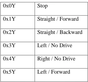
Control Bytes: Control Bytes are constructed in Hex like this:
0xXY
Where X is the direction and Y is the speed. The speed (Y) ranges from 0-F in hexadecimal, a range of 16 different speed. A table below shows the different drive commands:
Table 1: I-racer instruction sets.
0x0Y Stop
0x1Y Straight / Forward 0x2Y Straight / Backward
0x3Y Left / No Drive
0x4Y Right / No Drive
27
0x6Y Right / Forward
0x7Y Left / Backward
0x8Y Right / Backward
For example: If you want to drive left pretty darn quick, just send a 0x5B. If you want to backup to the right slowly, send a 0x85. All commands are sent as single bytes at 9600 baud, 8-N-1.
Bluetooth:
The Android platform includes support for the Bluetooth network stack, which allows a device to wirelessly exchange data with other Bluetooth devices. The application framework provides access to the Bluetooth functionality through the Android Bluetooth APIs. These APIs let applications wirelessly connect to other Bluetooth devices, enabling point-to-point and multipoint wireless features. Bluetooth is used to carry over the data from the android device to the I-Racer robot car, and navigate based on the analysis of these data. All of the Bluetooth APIs are available in the android.bluetooth package. In order to use Bluetooth features in my application, I declared the Bluetooth permission BLUETOOTH. This permission is needed to perform any Bluetooth communication, such as requesting a connection, accepting a connection, and transferring data.
Arduino:
Arduino is a single-board microcontroller, intended to make the application of interactive objects or environments more accessible.[1] The hardware consists of an open-source hardware board designed around an 8-bit Atmel AVR microcontroller, or a 32-bit Atmel ARM. Current models
28
feature a USB interface, 6 analog input pins, as well as 14 digital I/O pins which allows the user to attach various extension boards. Initially the arduino was used to test the sonar sensors.
Figure 7. An Arduino Mega
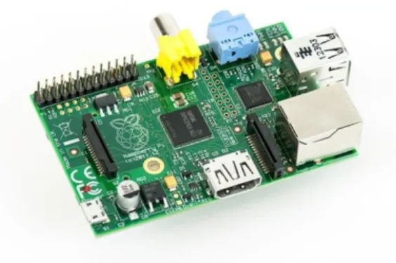
Raspberry PI:
The Raspberry Pi is a credit card-sized single-board computer developed in the UK by the Raspberry Pi Foundation with the intention of promoting the teaching of basic computer science in schools. The Raspberry Pi is manufactured in three board configurations through licensed manufacturing deals with Newark element14 (Premier Farnell), RS Components and Egoman. These companies sell the Raspberry Pi online. Egoman produces a version for distribution solely in China and Taiwan, which can be distinguished from other P is by their red coloring and lack of FCC/CE marks. The hardware is the same across all manufacturers. In the early prototypes the Raspberry Pi was used as the brain (processing unit) of the car.
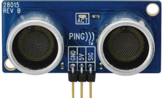
29 Ultrasonic Sensors:
Ultrasonic sensors work on a principle similar to radar or sonar, which evaluate attributes of a target by interpreting the echoes from radio or sound waves respectively. This is used in this self-driving car to detect what obstacle lies in the front.
Figure 9. Ultrasonic sensor or Sonar sensor
Ultrasonic sensors operate by generating a high-frequency pulse of sound, and evaluating the properties of the echo pulse that is received. There are three different properties of the received echo pulse that may be evaluated for different sensing purposes:
1) Time of flight- for sensing distance 2) Doppler shift- for sensing velocity
3) Amplitude attenuation- for sensing distance, directionality, or attenuation coefficient
In my case, I have used the time of flight property to determine the distance of obstacles.
The sensors used are the form of a pair of eyes, because of the two key parts of the sensor: the transmitter and the receiver.
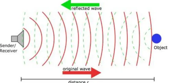
The transmitter emits a short burst of sound in a particular direction and the receiver collects the sound reflected back by obstacles. Distance traveled (d) can be calculated by measuring the time
30
taken (t) by the sound to return to the receiver based on the speed of sound (s) by the following equation:
d = s*t
In this case, the distance calculated will be twice the distance from the sensor to the obstacle.
So the distance (r) of the obstacle could be calculated by the following equation: r = d/2
Figure 10. How ultrasonic sensors work
The effective working angle of these sonar sponsors are approximately 30°. Therefore, measurement will consequently be more accurate within the central cone of 30°, and less accurate towards the sides. But this property can be an advantage towards a more effective scan of the environment, and narrow objects, such as chair legs.
31 Compass:
Most Android-powered devices have built-in sensors that measure motion, orientation, and various environmental conditions. These sensors are capable of providing raw data with high precision and accuracy, which can be used to monitor three-dimensional device movement or positioning, or to monitor changes in the ambient environment near a device. In our case the geomagnetic field sensor and accelerometer have been used to report a compass bearing. It is a 360° reading with respect to north. This sensor reading is very essential for the car to decide which way to drive.
32
CHAPTER 4
4.1
Google Maps API V2
As mentioned above about the detailed process of how the google map API was integrated to this research and the features and usages, here we discuss the implementation of the path finding process, the algorithms used to develop the navigation process of the automaton of the car [15].
4.2
Legs
One of the components of the Google Maps API is the The Directions Results Object. Among four sections of the Direction Results Object Routes Legs Steps and Transit Specific Information, I have used the Legs component. A Directions Leg defines a single leg of a journey from the origin to the destination in the calculated route. For routes that contain no waypoints, the route will consist of a single "leg," but for routes that define one or more waypoints, the route will consist of one or more legs, corresponding to the specific legs of the journey.
33
steps[] contains an array of Directions Step objects denoting information about each separate step of the leg of the journey.
distance indicates the total distance covered by this leg, as a Distance object of the following form:
value indicates the distance in meters
text contains a string representation of the distance, which by default is displayed in units as used at the origin. (For example, miles will be used for any origin within the United States.) You may override this unit system by specifically setting a Unit System in the original query. Note that regardless of what unit system you use, the distance.value field always contains a value expressed in meters.
These fields may be undefined if the distance is unknown.
4.3
Decimal degree
Positive latitudes are north of the equator, negative latitudes are south of the equator. Positive longitudes are east of Prime Meridian, negative longitudes are west of the Prime Meridian. Latitude and longitude are usually expressed in that sequence, latitude before longitude [17].
Precision: The radius of the semi-major axis of the Earth at the equator is 6,378,160.0 meters resulting in a circumference of 40,075,161.2 meters. The equator is divided into 360 degrees of longitude, so each degree at the equator represents 111,319.9 metres or approximately 111.32 km. As one moves away from the equator towards a pole, however, one degree of longitude is multiplied by the cosine of the latitude, decreasing the distance, approaching zero at the pole. The number of decimal places required for a particular precision at the equator is:
34
Table 2: Degree precision versus length
Decimal degree precision versus length decimal places degrees N/S or E/W at equator E/W at 23N/S E/W at 45N/S E/W at 67N/S 0 1.0 111.32 km 102.47 km 78.71 km 43.496 km 1 0.1 11.132 km 10.247 km 7.871 km 4.3496 km 2 0.01 1.1132 km 1.0247 km .7871 km 0.43496 km 3 0.001 111.32 m 102.47 m 78.71 m 43.496 m 4 0.0001 11.132 m 10.247 m 7.871 m 4.3496 m 5 0.00001 1.1132 m 1.0247 m .7871 m 0.43496 m 6 0.000001 111.32 mm 102.47 mm 78.71 mm 43.496 mm 7 0.0000001 11.132 mm 10.247 mm 7.871 mm 4.3496 mm 8 0.00000001 1.1132 mm 1.0247 mm .7871 mm 0.43496 mm
A value in decimal degrees to a precision of 4 decimal places is precise to 11.132 meters at the equator. A value in decimal degrees to 5 decimal places is precise to 1.1132 meter at the equator. The place where the research has been conducted is near 23N/S, so the according values from the table above have been used for more precise results. Elevation also introduces a small error. At 6,378 m elevation, the radius and surface distance is increased by 0.001 or 0.1%. Because the earth is not flat, the precision of the longitude part of the coordinates increases the further from the equator you get. The precision of the latitude part does not increase so much,
35
more strictly however, a meridian arc length per 1 second depends on latitude at point concerned. The discrepancy of 1 second meridian arc length between equator and pole is about 0.3 metres because the earth is an oblate spheroid. Since cars usually don’t drive that far, this marginal errors can be discarded.
A DMS value is converted to decimal degrees using the formula:
For instance, the decimal degree representation for 5 38° 53′ 23″ N, 77° 00′ 32″ W
(the location of the United States Capitol) is 38.889722°, -77.008889°
In most systems, such as Google Maps, the degree symbols are omitted, reducing the representation to
38.889722, -77.008889
To calculate the D, M and S components, the following formulas can be used:
6
where |DD| is the absolute value of DD, trunc is the truncation function, and mod is the modulo
36
CHAPTER 5
4.1
Development Phase
The total development process of my Self-driving I-racer could be divided into 4 phases. Based on the 4 phases there are 4 prototypes:
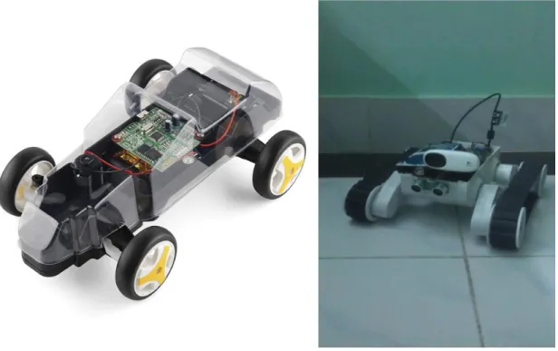
1. Prototype 1: Towards the beginning of the project I used a totally different type of robotic car kit as my car. It was a tank like vehicle. The maneuvering system was totally different from traditional cars. It maneuvered like a rank, so it could turn to any direction staying in the same position. Later I moved on to a more carlike robotic car kit, the I-racer.
37
Figure 12. Prototype 1
2. Prototype 2: The setup of the prototype car used in this research is quite simple. In the earlier setup a small breadboard was mounted on top of the I-Racer. Sonar sensors and a Raspberry Pi along with a power supply unit for the Raspberry Pi was mounted on top of the breadboard. The breadboard was used as a platform as well as a means for connecting the sonars and the Raspberry Pi with wires. This prototype was used to detect obstacles on the pathway of the car; and the Raspberry Pi was the processing unit of the self-driving car system.
38 Figure 13. Prototype 2
3. Prototype 3: In the later setup the Raspberry Pi was replaced with an Android phone because of the availability of the integrated GPS, Bluetooth and various sensors. Due to lack of space the sonar sensors were removed. The magnetic field created from the magnets in the motor interfered with the geomagnetic field sensor which resulted in faulty compass readings. So the whole car was first wrapped with electrical wire, then the phone was put on top of the car. So that the electrical field created on the coil of wire would negate the magnetic field. This resulted in a more stable compass reading. By
39
locating the current position of the car and calculating the heading direction this prototype was able to drive in real driving environment. Since the sonar sensors were removed the car couldn’t drive and detect obstacles at the same time. So the test drives were commenced in a traffic free environment. This prototype was used to test the ability to follow the pathway of a map; in this case the Google Map.
40
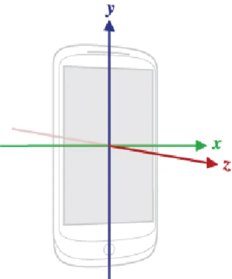
4. Prototype 4: The development of this phase is basically the combination of Prototype 2 and 3. With a few design changes I was able to mount both the obstacle detection module and the main processing module, the Android Phone, on top of the small chassis of a robotic car kit, the I-racer. It was observed that, putting the phone on top of the car vertically, rather than flat on top of it, creates less noise for the sensors in the phone. This also saves up a lot of space for the other hardware, like the raspberry pi and its power supply unit, which are also placed vertically in order to save space. The design outlook is as the following images:
41
4.2
System Diagram
42
4.3
Processing Pipeline
Figure 17. Processing Pipeline
4.4
How it works:
The overall work flow of the self-driven car could be represented sequentially like this:
The app shows the current location of the car on the google map. Target location is set by touching on the destination point on the map The current location is marked as ‘A’ and the destination as ‘B’
The path from A to B is determined by the Google Directions API. The path from A to B is actually a set of coordinates that form a line, thus the path. These coordinates could be considered nodes.
43
The car can reach its destination by iterating through each node, eventually leading to the destination.
There is an angle between two coordinates. This is called the ‘heading’. The Car also has a heading. It is the direction it is going on.
The goal of the car is to try and maintain the heading between the current position and the next node.
While traveling the course, if the car detects any obstacle, its instant response is to move away towards the next best direction and avoid it.
So, though the main goal is to reach the destination, each node can be considered a current goal. Upon reaching the current goal, the next node becomes the goal; so recursively the car iterates through each current goal to the final goal.
4.5
Steps:
1. Find Current Position ‘A’: The global position of the car is determined by the Global Positioning System (GPS) of the Android Phone. Google Map is used to visualize the position. Google Maps API V2 has been used here. The current position is a coordinate consisting of a latitude and a longitude value.
44 Figure 18. Localization
45
2. Set Destination ‘B’: The destination can be set from the user interface, by clicking on a point on the map. The destination also denotes a coordinate.
46
3. Find Path from A to B: The path from A to B is determined by the Google Directions API. The path from A to B is actually a set of coordinates that form a line, thus the path. These coordinates could be considered nodes.
47
4. Drive from A to B (Control): The control system could be divided into 2 categories: i) Global Control: In this category, the priority is to reach destination. So, the
actions taken during this process focused on achieving that. One of the key component is calculating the heading.
Once the path is set, the car starts its journey from the first node, which is the current location of the car. The immediate next node is the current goal for the car. The heading direction between the car’s current position and the current goal is calculated frequently as the car moves towards it. This is its desired heading. The car has its own heading direction. It constantly tries to keep its own heading towards the desired heading by steering towards it. If it is driving in the right direction, eventually it will reach the current goal. Once the current goal is reached, the next node becomes the current goal and the car drives towards it. This way all nodes are traversed and the final goal is reached.
48
Now since the steering angle of the I-Racer is fixed, the car overshoots. Meaning, by the time it reaches the desired heading angle and straightens the wheels it may have gone slightly off track. And this keeps happening from time to time, making the car sway a little left and right. So the traveled path isn’t always a straight like. This problem could be solved by gradually decreasing the steering angle as the car’s heading gets closer to the desired heading. But in order to do that a car of which the steering wheel can be controlled by the degree is needed.
Figure 22. Wavy track
Calculating Heading: The earth is not a true sphere but rather an oblate ellipsoid (sometimes called an oblate spheroid) with the poles being slightly flattened and the equatorial regions being slightly bulged out.
The earth's polar flattening is about 1 part in 298, resulting in an equatorial radius of 3963.191 miles (6378.137 km) and a polar radius of 3949.903 miles (6356.7523 km). The polar flattening is so slight that it would be hard to detect
49
with the human eye alone, however, it does make a significant difference when calculating long distances on the surface of the earth.
As a result, your current heading will vary as you follow a great circle path (orthodrome); the final heading will differ from the initial heading by varying degrees according to distance and latitude.
Heading is calculated by the following formulae:
θ = atan2( sin Δλ ⋅ cos φ2 , cos φ1⋅ sin φ2 − sin φ1⋅ cos φ2⋅ cos Δλ )
This formula is for the initial bearing (sometimes referred to as forward azimuth) which if followed in a straight line along a great-circle arc will take you from the start point to the end point. But since we are calculating short distances, for instance within the same city, the change in heading is negligible [18].
ii) Local Control: During the Local Control phase, the car is focused on avoiding obstacles. It can override the Global control command, even if it means to get away from the destination; once obstacle avoided, it goes back to course of Global control. The local control includes the Obstacle Detection System.
4.6
The Obstacle Detection System
Ultrasonic sensors are the heart of the Obstacle Detection System. Why ultrasonic sensors? Because they are cheap and easily available, and they get the work done. Four sonar sensors have been used on four sides of the car, giving it the coverage of its surrounding.
The initial formation of the sensors was 90o from each other; so basically it could cover top, right, back, and left side of the car, as the following diagram:
50 Figure 23. Initial formation of sonar sensors
The downside of this formation was, that the car couldn’t detect the corners.
Since a car is normally focused on going forward, the right and left sensors were slightly moved towards the front, covering the front-right and front-left corner consecutively. This change made a major difference in obstacle detection while moving. It could detect most corners before turning left or right.
51 Figure 24. Later positioning or sonar sensors
52
4.7
Algorithm
The AI for the self-driving car was implemented on Java platform. An android app was made to interface between the phone and the I-Racer. The driving algorithm of the car can be represented by the following processing pipeline and flow chart:
53 Figure 25. Algorithm flow chart
54
CHAPTER 5
5.1 Output and Result
Several test drives have been conducted to find the output of the program. Which led to a lot of bug fixes. The output of the program depended on a few external things, like- electromagnetic field from the motor of the I-Racer, the GPS signal quality, the phone’s operator signal. Because of these thing the output fluctuated from time to time, causing the car to drive in a wrong way; that’s why outdoor testing didn’t give any satisfactory result, other than the fact that for the initial time while it is on course, the car is able to steer towards the desired heading keeping it on track. And the wavy track was noted.
The following image shows the inaccurate GPS readings. The desired path is marked by the red lines. The orange marker marks the starting location, and the blue marker marks the destination. When manually travelled down the path, the GPS signals fluctuated a lot. The green markers show the GPS track that was obtained.
55 Figure 26. Inaccurate GPS signals
Indoor test drives have also been conducted. The target was to test the obstacle detection functionality of the car. It was able to move freely indoors, avoiding obstacles, even coming out of corners.
Though fixed sensors handled the job of obstacle detection pretty well, the car still had some blind spots. The total 360o surrounding was not covered. This can be overcome by having a
56
rotating sonar sensor, or more expensive sensors that take a rotational 360o scan of the environment. Storing this surrounding information would help create a map of the environment the car is in, thus provide better Localization. And with more precise sensing of the velocity and displacement of the car’s movement, the car could be able to perform more precise driving while Global Control is uncertain.
Google car uses a very expensive Lidar to achieve better Localization. It senses the surrounding and stores all the data creating a map. So, the next time the car comes down the same road, it knows how to react.
5.3
Advantages and Disadvantages
We are often concerned about the usability, safety and benefits of autonomous cars. However the advantages listed below may change anyone’s mind. It reduces the number of accidents. This is well-supported by the concept that sensors are more accurate than humans. Anyone can use the car. Elderly people, children and those who are disabled can easily use the autonomous cars according to their needs. There is no need to wait for someone who can drive them to their intended location. Lot of free time for those who use the car. A lot of time can be saved for those people who drive. They can utilize the same time for doing something else like reading or watching a movie as we don’t need to worry much about the journey. There is no need for a driving license. It is a more efficient public transport system. And it takes less time to reach the destination. The autonomous cars may be running with a much higher speed limit once they are fully established commercially on the roads. It may also reduce number of staff like the traffic
57
police and ensure the hassle free parking anywhere. It can even contribute in controlling pollution to an extent.
Major concerns regarding the use of autonomous cars are also not out of the plate. Some are discussed below. A fear about an occurrence of an accident is always there in the minds of people as the possibility of the computer crashing or malfunctioning cannot be ruled out. Do we need separate roads for all the autonomous cars? Do they run along with the manually driven cars on the same path? How safe is it if both types of the cars are using the same route of travel? These questions can be answered only after successful research that need a bit more time. There is less importance for drivers. We depend on drivers a lot for our day to day life. By the emergence of driverless cars on the road, a significant percentage of people in the driving profession may lose their job as even the taxis may run without a driver. Hackers taking control of computer-driven technology is another cause of worry. By hacking into the system, they can use the vehicles for destructive purposes. Liability of an accident is another issue of concern. When a driverless car is met with an accident, who is accountable for it? This question seems to be an unanswered one until new laws and regulations are made with respect to the usage of autonomous cars. It appears really difficult to find out whom to blame for an accident? Is it the vehicle owner? If it is the fault of a component or software of the car, who will be liable for the accident? Will it be the owner whose responsibility is to check the condition of the car regularly or the manufacturer of the car?
58
CHAPTER 6
6.1 Conclusion
The aim of this project is to design an autonomous vehicle driving system, to develop the artificial intelligence that would be able to make a driver less automobile safe enough to drive on the road. The goal was to develop a program that would run in an android operated environment and will be able to control the vehicle, thereby taking the responsibilities of the driver, providing a more manageable control over it. And a swarm of these autonomous vehicles could just be the solution to our traffic problems and traffic jam, reduce the number of road accidents and nevertheless save the time that people engage themselves while driving for some other task.
59
6.2
Future Work
This research work can be further extended to the improvement of the autonomous system, for better perception and navigation. Furthermore, if the aspect of image processing can be incorporated with this system by attaching a camera to the car, the magnitude of the research project would be multiplied by manifold. I would like to work on 2D and 3D map building techniques using various sensors for better localization. Though a lot of work is being done in the field of self-driving cars by researchers and major car manufacturing companies, most of it remain company secret. So the scope still remains for more research and development of this existing system of automated self-driving car.
60
R
EFERENCES[1] Autonomous car. (2015, August 18). In Wikipedia, The Free Encyclopedia. Available:
https://en.wikipedia.org/w/index.php?title=Autonomous_car&oldid=676696225
[2] History of autonomous car. (2015, August 6). In Wikipedia, The Free Encyclopedia.
Available:
https://en.wikipedia.org/w/index.php?title=History_of_autonomous_car&oldid=674883593
[3] "U.S. Department of Transportation Releases Policy on Automated Vehicle Development". (2013, May 30). National Highway Traffic Safety Administration. Available:
http://www.nhtsa.gov/About+NHTSA/Press+Releases/U.S.+Department+of+Transportation+Rel eases+Policy+on+Automated+Vehicle+Development
[4] The Optical Society. (2014, May 29). New laser sensing technology for self-driving cars,
smartphones and 3-D video games. ScienceDaily. Available:
www.sciencedaily.com/releases/2014/05/140529100732.htm
[5] Google driverless car. (2015, August 23). In Wikipedia, The Free Encyclopedia. Available:
https://en.wikipedia.org/w/index.php?title=Google_driverless_car&oldid=677413590
[6] Thrun, S.; Montemerlo, M.; Dahlkamp, H.; Stavens, D.; Aron, A.; Diebel, J.; Fong, P.; Gale, J.; Halpenny, M.; Hoffmann, G.; Lau, K.; Oakley, C.; Palatucci, M.; Pratt, V.; Stang, P.; Strohband, S.; Dupont, C.; Jendrossek, L. E.; Koelen, C.; Markey, C.; Rummel, C.; Niekerk, J.; Jensen, E.; Alessandrini, P.; Bradski, G.; Davies, B.; Ettinger, S.; Kaehler, A.; Nefian, A.;
61
Mahoney, P. (2007). "Stanley: The Robot That Won the DARPA Grand Challenge". The 2005 DARPA Grand Challenge. Springer Tracts in Advanced Robotics
[7] Google Maps. (2015, August 23). In Wikipedia, The Free Encyclopedia. Available:
https://en.wikipedia.org/w/index.php?title=Google_Maps&oldid=677511107
[8] Barry B