International Journal of Industrial Electronics, Control and Optimization .
© 2019 IECO….Vol. 2, No. 2, pp. 145-154, April (2019)
Microgrid frequency control using the virtual inertia and
ANFIS-based Controller
Akbar Karimipouya
1, Shahram karimi
†2and Hamdi Abdi
3†,1,2,3
Department of Electrical Engineering, Razi university, Kermanshah, Iran
The main challenge in associate islanded Micro grid (MG) is the frequency stability due to the inherent low-inertia feature of distributed energy resources. That is why, energy storage devices, are utilized in MGs as the promising sources for grid short-term frequency regulation. Though energy storage devices, improve the dynamic operation of the load-frequency control (LFC) system, these devices increase system costs. Moreover, the modification or uncertainty of the system parameters will significantly degrade the performance of the conventional LFC system. This article proposes the execution of rotating-mass-based virtual inertia in Double-Fed Induction Generator (DFIG) to support the first frequency control associated an adaptive Neuro-Fuzzy inference System (ANFIS) controller, as secondary frequency control. The simulation conclusions illustrate that the suggested control scheme ameliorate the dynamic operation of the LFC system and also the studied islanded MG remains stable, despite severe load variation and parametric uncertainties.
Article Info
Keywords:
Microgrid, Frequency Control,
DFIG, Virtual Inertia, Fuzzy PID Controller, ANFIS.
Article History:
Received 2018-08-05
Accepted 2018-12-09
I.
I
NTRODUCTIONIn recent decades, the use of renewable energy has enhanced, the main cause of which is environmental pollution and economic aspects [1]. Wind energy has become one in all the most necessary renewable energies and the largest view in terms of new technologies and economical. Due to the variable speed of wind, for maximum efficiency at different speeds, the turbine with variable speed is required
[2,3].Therefore, the wind turbine equipped with Double-Fed
Induction Generators (DFIGs) are widely utilized in Wind
Energy Conversion System (WECS) [4]. There
is generally no inertia response between the DFIG rotor speed and the frequency of the system. There is additionally no primary frequency regulation and only the maximum power point tracking (MPPT) method is used in DFIG power control system [5]. Therefore, with high wind power penetration, inevitably there are major challenges in frequency regulation. In addition, the main challenge in an islanded Micro grid (MG) is the frequency stability due to the
inherent low-inertia feature of Distributed Energy Resources (DERs). That is why, energy storage equipment, because of their rapid response time and ability to charge and discharge efficiently, are used in MGs as the promising sources for grid short-term frequency regulation [6]. Although energy
storage instruments, like batteries, flywheels, and
super-capacitors, improve the dynamic operation of the Load-Frequency control (LFC) system, these devices, along with their respective inverter, increase system costs.
Wind turbines participation in frequency adjustment is the idea to make better the dynamic frequency respond characteristics of power systems. In [7-15], by implementing virtual inertia in DFIG control system, the dynamic behavior of the MG is improved. In [7, 8], the primary frequency control strategy, virtual inertia and blade angle control are used in DFIG to reduce the frequency variation. In [9, 10], the super-capacitor, as the source of inertia, has been used. In [11], using double-layer capacitor energy storage, dynamic stability is improved. These methods also, due to the use of additional equipment, is costly. In [12-15], the inertia of the wind turbine rotating mass is used to implement virtual inertia in DFIG control system. Although implementation of
† Corresponding Author: [email protected]
*
Electrical Engineering Department, Razi University, Kermanshah, Iran A
International Journal of Industrial Electronics, Control and Optimization .
© 2019 IECO 146virtual inertia with rotating masses does not require additional equipment and costs, its implementation is subject to some limitations. In this method, the virtual inertia appertain to the wind speed, and therefore, its value is completely variable and stochastic. Another limitation to the use of rotating-mass-based virtual inertia is a thermal constraint. At high wind speeds, frequency deviation leads to the additional power generation, due to the virtual inertia control loop, and consequently, the temperature of the DFIG rises, which may be more than allowed [13]. Moreover, in this paper, it is shown that the change or uncertainty of the system parameters, such as droop factor, can considerably degrade the performance of the LFC system.
Contrariwise, in the conventional LFC systems, the PI or PID controllers are usually used as secondary frequency control. Although these controllers have such advantages as simplicity and easy implementation, they are mostly used for systems with simple and constant configuration. Therefore, because the structure and configuration of micro grids are constantly changing and there are many uncertainties, conventional controllers with constant parameters cannot be used. [15]. Also, Most of the linearization methods used to control the frequency increase the system's order, which makes the micro grid more complicated [16].
Fuzzy logic and neural controllers also have been developed in many control applications to intricate models [17]. The fuzzy is based on the rules "if and then", which we get these rules from the system description. Since we do not have much information about the behavior of most systems, conclusion from these types of systems is difficult and neural controllers need a lot of time for training. Combined methods are among the methods developed to control complex systems in recent years. One of these combined algorithms is Adaptive Neuro-Fuzzy Inference System (ANFIS). An ANFIS benefits from both fuzzy and neural control systems. In this paper, instead of the conventional PID controller, an ANFIS-based controller is proposed to use as secondary frequency control while the rotating-mass-based virtual inertia is implemented to support the primary frequency control.
So far, several intelligent controllers have been explored as complementary frequency control of micro grids. In [6], frequency control has been improved using the fuzzy-PSO method with the amount of electric power generated by wind turbines. In [18], frequency control has been improved using
the HPSO algorithmdecentralized. In [19] using fuzzy logic,
control for the micro grid frequency is done with high
penetration of wind turbines. In [20], frequency control is
performed using an on-line method that detects frequency variations using PSO and fuzzy algorithms. But until now, research on the use of ANFIS-based controller as complementary frequency control of the micro grid has not been reported when virtual inertia is involved in the LFC system.
The rest of this study is segmented as follows: The second part describes the model of the micro grid studied. In Section 3, the implementation of rotating-mass-based virtual inertia in
DFIG are explained. Fuzzy PID and ANFIS-based controllers’ design are addressed in part 4. Results and simulations of different controllers and their comparison are presented in
part 5. Eventually, the general conclusionis summarized in
part 6.
II.
THE
STUDIEDMG
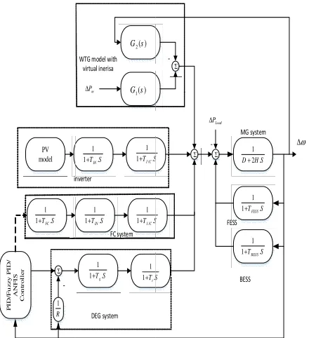
STRUCTUREFigure 1 shows an islanded micro grid containing various DGs. This system includes wind turbine, solar cell, diesel generator, fuel cell, battery and flywheel storage devices. The parameters of the studied MG are also presented in Table 1.
In the studied MG, as shown in Fig. 1, diesel generator consists of the primary and complementary frequency control loop Also, a complementary frequency control loop; control the fuel cell output power. Droop control is used for the primary frequency control and the storage devices are used for supporting the primary frequency control. Different controllers are designed for the secondary frequency control loops. These controllers are the classical PID controller, PID fuzzy and proposed ANFIS-based controller.
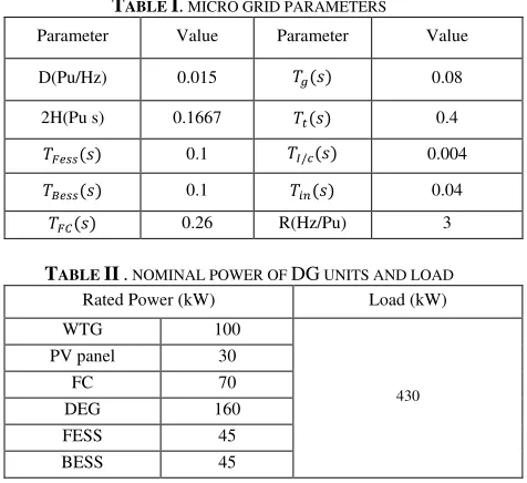
TABLE I. MICRO GRID PARAMETERS
TABLE II. NOMINAL POWER OF DG UNITS AND LOAD
Load (kW) Rated Power (kW)
430
100 WTG
30 PV panel
70 FC
160 DEG
45 FESS
45 BESS
Value Parameter
Value Parameter
0.08
( )
0.015 D(Pu/Hz)
0.4
( )
0.1667 2H(Pu s)
0.004
/( )
0.1
( )
0.04
( )
0.1
( )
3 R(Hz/Pu)
0.26
International Journal of Industrial Electronics, Control and Optimization .
© 2019 IECO 147PV model
WTG model
Σ Σ
Σ
P
I
D
/F
u
z
z
y
P
I
D
/
A
N
F
I
S
C
o
n
tr
o
l
le
r
1
1+T SIN. /
1 1+T SI C.
1 1+T SFC.
1
1+T SIN. /
1 1+T SI C.
1 1+T St. 1
1+T Sg.
1 2 .
D+H S
1 1+TFESS.S
1 1+TBESS.S m
P
∆
Load
P
∆
f
∆
1
R
inverter
FC system
DEG system
MG system
FESS
BESS
-Fig.1. schematic block diagram of the studied islanded MG.
III.
I
MPLEMENTING VIRTUAL INERTIAIn a DFIG, stator directly and rotor via two converters connected to the power system. It produces the highest wind power using a converter that is located on the rotor's side and it adjusts the stator voltage. DC voltage can be adjusted using the network side converter. Wind turbines such as synchronous generators have high inertia, which this energy is stored as kinetic in its axis. However, this energy cannot participate in frequency adjusting due to the decoupled mechanical and electrical power controllers.
The maximum power that can be obtained from a wind turbine, Pm, opt can be expressed
(1) 3
,
m opt opt m
P =K
ω
Where ωm is DFIG rotational speed and Kopt is fixed
when the angle of the turbine blade is constant.
The input mechanical and the output electrical powers (Pm, Pe) are related to each other as the following
(2)
− =
In this equation, J is the moment of inertia of the rotating mass connected to the rotor.
In synchronous generators, in order to control the grid frequency, a speed governor controls the input mechanical power. As a result, the generator output power depends on the input mechanical power and a derivative term that introduces the rotating mass inertia. In a DFIG, where Pm is undispatchable, the output electrical power is controlled directly. Therefore, the grid frequency variation and the rotating mass inertia do not affect the amount of generator output power. Thus, the DFIG inertia does not participate in frequency tuning.
If equation (2) is written in the per unit form, it is as follows:
(3)
2 m
m e m
d P P H
dt
− =
ω
ω
In this equation,
H
is the DFIG inertia constant and Pe isequal to Pm, opt. After linearization around the basis rotational
speed (3) can be represented as:
(4)
− = 2
Where,
(5)
2 0 3
e opt m m
P K ω ω
∆ = ∆
To implement virtual inertia, the output electrical power control is changed in such a way that, moreover to tracking the maximum power point, it also responds to system frequency variations. Therefore, the above equation can be modified as follows:
(6)
2
0 0
3 ( )
e opt m m m
P K ω ω Hν s ω ω
∆ = ∆ − ∆
In the above equation, the frequency of the grid is represented by ω and Hv(s) is the transfer function of virtual inertia, which represented as follows [22]:
(7)
1 2
( )
( 1)( 1)
M s
H s
s s
ν ν
τ τ
=
+ +
In the above transfer function, is the virtual inertial
constant, and
τ
1 andτ
2 are the virtual inertia timeconstants. At low frequencies, Hv(s) behaves similarly to a
derivative.
By replacing (6) in (4) we can write:
(8)
= 3!"# $ − ( )
+ 2
Using the above equation is obtained according to
the equation (9).
(9)
= 1
2 + 3!"# $
∆
+ ( )
2 + 3!"# $
By replacing (9) in (6) we will have:
= )*+,-./0
$1 2)*+,-./0
∆ − $113( )4/0 $1 2)*+,-./0
(10)
Based on (10), can be changed as a function of ∆
and . Therefore, the grid frequency variation and the
virtual inertia affect the amount of DFIG output power. By
setting
and consequently
Hv(s) to zero, windInternational Journal of Industrial Electronics, Control and Optimization
equipped with figure, the transf the first and second part
Fig.2
with virtual inertia.
IV.
controllers loop. The
of the proportional, integral and derivative conventional PI and PID controllers, value,
for different operation conditions and in presence of disturbances and uncertainties.
pa
that happen in the grid, the
One of the features of Fuzzy PID and controller
ANFIS
MG that is separated from the MG. diagram of the
PID
Fuzzy PID Controller
In this study, the MG
International Journal of Industrial Electronics, Control and Optimization
= ,"# −
Figure 2 shows equipped with DFIG figure, the transf the first and second part
PV model Σ P I D /F u z z y P I D / A N F I S C o n tr o ll e r 1 1+T SFC.
1
R
inverter
-Fig.2. the schematic block diagram of the studied islanded MG
with virtual inertia.
IV. FUZZY PID AN
In conventional power systems, conventional PI and PID controllers are often used
loop. The operation of these controllers pertain of the proportional, integral and derivative conventional PI and PID controllers, value, is not guaranteed
for different operation conditions and in presence of disturbances and uncertainties.
parameters can automatically that happen in the grid, the
One of the features of Fuzzy PID and controllers is the automatic adjustment of parameters.
The aim of this
ANFIS-based controller for complementary control loop in a MG that is separated from the MG.
diagram of the secondary frequency control ID and ANFIS
Fuzzy PID Controller
A. Design of Fuzzy PID Controller
Fuzzy rules have been created based on human knowledge. In this study, the fuzzy
the MG frequency error, and the other is der
International Journal of Industrial Electronics, Control and Optimization
64
6
shows adding of virtual inertia to the wind turbine DFIG in the s
figure, the transfer functions G1
the first and second part of the equation
2( )
G s
1( )
G s
1
1+T SIN. /
1 1+TI C.S
1
1+T SIN. /
1 1+TI C.S
1 1+T St. 1
1+T Sg. m P ∆ inverter FC system DEG system WTG model with virtual inerisa
. the schematic block diagram of the studied islanded MG with virtual inertia.
FUZZY PID AN ANFIS
In conventional power systems, conventional PI and PID often used in the secondary
operation of these controllers pertain of the proportional, integral and derivative conventional PI and PID controllers,
is not guaranteed to achieve the desired performance for different operation conditions and in presence of disturbances and uncertainties.
s can automatically tune
that happen in the grid, the desired performance achievable One of the features of Fuzzy PID and
is the automatic adjustment of parameters. this part is to design a Fuz
based controller for complementary control loop in a MG that is separated from the MG.
secondary frequency control and ANFIS-based controller
Fuzzy PID Controller is illustrated in Fig. 4.
Design of Fuzzy PID Controller
Fuzzy rules have been created based on human knowledge. the fuzzy block has
frequency error, and the other is der
International Journal of Industrial Electronics, Control and Optimization
of virtual inertia to the wind turbine studied islanded MG
1(s) and G2(s) are respectively of the equation (10).
Σ
Σ Σ
1T .S
1T .S
1T S.
Load P ∆ FESS
-. the schematic block diagram of the studied islanded MG
ANFIS-BASED CONTROLLER SESIGN
In conventional power systems, conventional PI and PID in the secondary frequency control operation of these controllers pertain
of the proportional, integral and derivative parameters. conventional PI and PID controllers, with fix parameters’
to achieve the desired performance for different operation conditions and in presence of disturbances and uncertainties. While the PID controller tune matching to the variations desired performance achievable One of the features of Fuzzy PID and
is the automatic adjustment of parameters.
part is to design a Fuzzy PID and an based controller for complementary control loop in a MG that is separated from the MG. Figure 3 shows the block
secondary frequency control using the based controller. The overall
is illustrated in Fig. 4.
Design of Fuzzy PID Controller
Fuzzy rules have been created based on human knowledge. block has two inputs, one of which is frequency error, and the other is der
International Journal of Industrial Electronics, Control and Optimization
(11)
of virtual inertia to the wind turbine tudied islanded MG. In this are respectively
1 2 .
D+H S
1 1+TFESS.S
1 1+TBESS.S
ω ∆ MG system
FESS
BESS
. the schematic block diagram of the studied islanded MG
BASED CONTROLLER
In conventional power systems, conventional PI and PID frequency control operation of these controllers pertains on the values parameters. Using with fix parameters’ to achieve the desired performance for different operation conditions and in presence of While the PID controller matching to the variations desired performance achievable.
ANFIS-based is the automatic adjustment of parameters.
zy PID and an based controller for complementary control loop in a igure 3 shows the block using the fuzzy The overall structure of
Fuzzy rules have been created based on human knowledge. two inputs, one of which is frequency error, and the other is derived from the
International Journal of Industrial Electronics, Control and Optimization
of virtual inertia to the wind turbine In this are respectively
. the schematic block diagram of the studied islanded MG
BASED CONTROLLER
In conventional power systems, conventional PI and PID frequency control on the values g with fix parameters’ to achieve the desired performance for different operation conditions and in presence of While the PID controller matching to the variations . based
zy PID and an based controller for complementary control loop in a igure 3 shows the block fuzzy structure of
Fuzzy rules have been created based on human knowledge. two inputs, one of which is ived from the
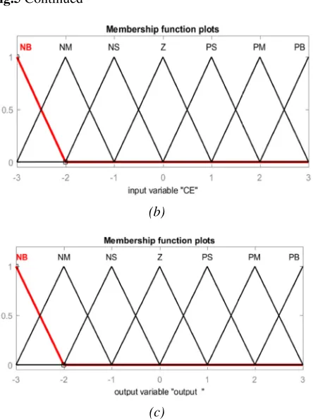
MG frequency error. The law that has been wri block is 49 laws;
range of membership func between
-Fig.3. Block diagram
1
e
Fig. 4. The overall structure of Fuzzy PID Controller
CE E NB NM NS Z PS PM PB
International Journal of Industrial Electronics, Control and Optimization
frequency error. The law that has been wri block is 49 laws; these rules
range of membership func
-3 and +3 as shown in Figure 5
. Block diagram of the MG frequency control
10
du/dt
Derivative 3.4285 3.4285
. The overall structure of Fuzzy PID Controller
TABLE III
NM NB NS NB Z NB PS NB PM NB PB NM Z NS PS Z
International Journal of Industrial Electronics, Control and Optimization .
© 201
frequency error. The law that has been wri these rules are fully written
range of membership functions for inputs and outputs shown in Figure 5
of the MG frequency control
-K--K E CE Fuzzy Inference System
. The overall structure of Fuzzy PID Controller
III.TABLE OF FUZZY RULES
Z NS NB NB NM NB NS NM Z NS PS Z PM PS PB PM (a)
© 2019 IECO
frequency error. The law that has been written for this fully written in table 3 tions for inputs and outputs shown in Figure 5.
of the MG frequency control
1/s K- -K-+ 1/S Limited Integrator Integrator PI Control Feed Forward PD Control
. The overall structure of Fuzzy PID Controller ABLE OF FUZZY RULES
PM PS NS NM Z NS PS Z PM PS PB PM PB PB PB PB
IECO 148
tten for this in table 3. The tions for inputs and outputs is
International Journal of Industrial Electronics, Control and Optimization
Fig.5
Fig. 5
block, b) Second input of the fuzzy block (Error derivative) c) output of fuzzy block
the fuzzy controller that
proposed be computed.
is to attain the highest control proficie the neural network,
controllers to the
Considering different scenarios such as load variation and parametric uncertainties, the output of each two controllers have been
finally have been used to teach the proposed ANFIS controller.
fuzzy system has 49 rules that amounts t
inputs (x
an error derivative
rules, if and then the fuzzy, which are in the Takagi Sugeno
first
described below.
International Journal of Industrial Electronics, Control and Optimization
Fig.5 Continued
Fig. 5. Membership functions: a) The error input of the fuzzy
block, b) Second input of the fuzzy block (Error derivative) c) output of fuzzy block
B. Design of ANFIS
The behaviour of the neuro the fuzzy controller
that the neural system has been added. To design the proposed ANFIS
be computed. Since the purpose of mode is to attain the highest control proficie the neural network,
controllers to the
Considering different scenarios such as load variation and parametric uncertainties, the output of each two controllers
have been recorded separately.
finally have been used to teach the proposed ANFIS controller.
The neural network used in this article has five layers fuzzy system has 49 rules that
amounts to two.
inputs (x, y), one of which is an error an error derivative
rules, if and then the fuzzy, which are in the Takagi
Sugenotype, are
first-order Sugeno described below.
International Journal of Industrial Electronics, Control and Optimization
Continued
(b)
(c)
Membership functions: a) The error input of the fuzzy block, b) Second input of the fuzzy block (Error derivative) c) output of fuzzy block.
Design of ANFIS-based controller
ur of the
neuro-the fuzzy controller and neuro-the only difference
he neural system has been added. To design the ANFIS-based controller, the training data must first
Since the purpose of mode is to attain the highest control proficie
the neural network, first, we apply classical and fuzzy controllers to the studied MG as
Considering different scenarios such as load variation and parametric uncertainties, the output of each two controllers
recorded separately.
finally have been used to teach the proposed ANFIS
The neural network used in this article has five layers fuzzy system has 49 rules that the
o two. It is supposed y), one of which is an error an error derivative (y = de) and has an output
rules, if and then the fuzzy, which are in the Takagi type, are the foundation
Sugeno system, it produces two rules that are described below.
International Journal of Industrial Electronics, Control and Optimization
(b)
c)
Membership functions: a) The error input of the fuzzy block, b) Second input of the fuzzy block (Error derivative) c)
based controller
-fuzzy controller
the only difference between them is he neural system has been added. To design the controller, the training data must first Since the purpose of modelling this controller is to attain the highest control proficiency, for
first, we apply classical and fuzzy studied MG as complement
Considering different scenarios such as load variation and parametric uncertainties, the output of each two controllers
recorded separately. These recorded data are finally have been used to teach the proposed ANFIS
The neural network used in this article has five layers the ANFIS system reduced this
that the fuzzy system has two y), one of which is an error (x = e), and the other is
and has an output z =f (x, y) rules, if and then the fuzzy, which are in the Takagi
the foundationof the fuzzy rules
system, it produces two rules that are
International Journal of Industrial Electronics, Control and Optimization
Membership functions: a) The error input of the fuzzy block, b) Second input of the fuzzy block (Error derivative) c)
based controller
fuzzy controller is similar to between them is he neural system has been added. To design the controller, the training data must first lling this controller ncy, for the training of first, we apply classical and fuzzy complementary control. Considering different scenarios such as load variation and parametric uncertainties, the output of each two controllers
These recorded data are finally have been used to teach the proposed ANFIS-based
The neural network used in this article has five layers.The
ANFIS system reduced this fuzzy system has two , and the other is
z =f (x, y).The
rules, if and then the fuzzy, which are in the Takagi and
of the fuzzy rules that for a system, it produces two rules that are
International Journal of Industrial Electronics, Control and Optimization
Membership functions: a) The error input of the fuzzy block, b) Second input of the fuzzy block (Error derivative) c)
similar to between them is he neural system has been added. To design the controller, the training data must first lling this controller the training of first, we apply classical and fuzzy . Considering different scenarios such as load variation and parametric uncertainties, the output of each two controllers These recorded data are based
The ANFIS system reduced this fuzzy system has two , and the other is The and that for a system, it produces two rules that are
Rule 1: if x is
Rule 2: if x is
Where
Where,
The structure of designed ANFIS is As shown in Fig.6, the output of ANFIS by,
Weights of the
preceding layer outputs and the output of the two rules outputs [2
The neural network structure is composed connected together with the notations
from layer
ANFIS model can be Layer 1:
function defined B i , 1 L A i , 1 L µ = µ =
Where e and
assigned fuzzy function to the node. Layer 1 is consisting of the input variables (membership functions). Membership functions can be defined
so on. For e function parameters a
Layer 2: computes node is the defined by,
Layer 3: i-th node
1 1 1 1
f =Pe+R e∆ +s
2 2 2 2
f P e R e s
e= −
e ∆ =
w f w f
f = =w f +w f
( )
1 i
A e
µ =
2,i i A B
L =W = e ∆e
International Journal of Industrial Electronics, Control and Optimization
Rule 1: if x is 78and y is
Rule 2: if x is 7$and y is
Where
Where, 9 :is the reference
structure of designed ANFIS is As shown in Fig.6, the output of ANFIS
Weights of the w1and
preceding layer outputs and the output of the two rules outputs [2
The neural network structure is composed connected together with the notations
rom layer j for the five layer ANFIS model can be Layer 1: In a layer, the i
defined by ) e ( B ) e ( A 2 i i ∆ −
Where e and ∆e are input to a node and
assigned fuzzy function to the node. Layer 1 is consisting of the input variables (membership functions). Membership functions can be defined
so on. For example, A
function parameters as follows:
Layer 2: each node in computes the firing power node is the result of whole
by,
Layer 3: every node in node computes the respect
1 1 1 1
f =Pe+R e∆ +s
2 2 2 2
f =P e+R e s∆ +
ref r
e=
ω
−ω
( ref r) d
e
dt
ω −ω
∆ =
1 1 2 2
1 2 w f w f
f w f w f
w w + = = + + 2 1 1 i b i i e c a − + ( ) ( ) i i
i i A B
L =W =µ e µ ∆e
International Journal of Industrial Electronics, Control and Optimization .
© 201and y is ;8then:
and y is ;$then:
eference angular structure of designed ANFIS is depicture As shown in Fig.6, the output of ANFIS
and w2 are obtained as the product of the
preceding layer outputs and the output f
of the two rules outputs [23, 24].
The neural network structure is composed
connected together with the notations L
layers.
ANFIS model can be defined as below
In a layer, the i-th node corresponds to the node
e are input to a node and
assigned fuzzy function to the node. Layer 1 is consisting of the input variables (membership functions). Membership functions can be defined as triangular form or Gaussian, and
Ai can be membership by
s follows:
node in which layer is a
power wi of a rule. The output of
whole the entry
node in which layer is a the respect of the i
2 2 2 2
f =P e+R e s∆ +
1 1 2 2 f = =w f +w f
( ) ( )
L W e e
© 2019 IECO
angular speed.
depictured in Figure 6. As shown in Fig.6, the output of ANFIS can be represented
(1
are obtained as the product of the
f is a weighted average
The neural network structure is composed of five
Lj,ifor the output node i
below.
th node corresponds to the node
e are input to a node and Ai and
assigned fuzzy function to the node. Layer 1 is consisting of the input variables (membership functions). Membership triangular form or Gaussian, and can be membership by Gaussian
layer is a constant node of a rule. The output of
entry signals to it and is
layer is a constant node. Each i-th rule’s firing
IECO 149
(12)
(13)
(14)
(15)
d in Figure 6. represented
(16)
are obtained as the product of the is a weighted average
five layers for the output node i
th node corresponds to the node
(17)
Bi-2are assigned fuzzy function to the node. Layer 1 is consisting of the input variables (membership functions). Membership triangular form or Gaussian, and Gaussian
(18)
node that of a rule. The output of every signals to it and is
(19)
International Journal of Industrial Electronics, Control and Optimization
to the
output from the defined
node function
resultant parameter collection.
computes the total output as the aggregate of whole entry signals, i.e.
the ANFIS reduced this value to 2. designed
Figure
Fig. 6
Fig. 7
L W
International Journal of Industrial Electronics, Control and Optimization
to the aggregate output from the defined by,
Layer 4: In a layer, the node function defined
Where <=is the output of Layer 3 and {
resultant parameter collection. Layer 5: This layer
computes the total output as the aggregate of whole entry signals, i.e.
The base fuzzy system has 49 rules (Figure the ANFIS reduced this value to 2.
designed ANFIS Figure 8. e e ∆ 1 A 2 A 2 B 1 B Layer1
Fig. 6. The structure of the designed ANFIS controller
Fig. 7. Fuzzy rules
3, 1 2 i i i W L W W W = = +
4,i i i i i i i
L =W∗f =W .(P e+R∆ +e s )
5,i i i i
L =
∑
W .f =International Journal of Industrial Electronics, Control and Optimization
of firing powers
output from the i-th node is the normalized firing
In a layer, the i defined by,
=is the output of Layer 3 and {
resultant parameter collection. Layer 5: This layer contains just
computes the total output as the aggregate of whole entry
The base fuzzy system has 49 rules (Figure the ANFIS reduced this value to 2.
ANFIS-based controller in MATLAB illustrated i
Π Π Ν Ν 1 W 2 W Layer2 Layer3
. The structure of the designed ANFIS controller
. Fuzzy rules-based system for studied MG
1 2
W W
4,i i i i i i i
L =W∗f =W .(P e+R∆ +e s )
i i i 5,i i i i W .f
L W .f
W = =
∑
∑
International Journal of Industrial Electronics, Control and Optimization
powers of whole node is the normalized firing
i = 1, 2
i-th node corresponds to the
i=1,2
is the output of Layer 3 and {
contains just one constant node that computes the total output as the aggregate of whole entry
The base fuzzy system has 49 rules (Figure
the ANFIS reduced this value to 2. The structure of based controller in MATLAB illustrated i
e∆e
e ∆ e Ν Ν 11 W .f 2 W .f 2 W 1 W Layer3 Layer4
. The structure of the designed ANFIS controller
based system for studied MG
4,i i i i i i i
L =W∗f =W .(P e+R∆ +e s )
International Journal of Industrial Electronics, Control and Optimization
the rules. The node is the normalized firing power
i = 1, 2 (20)
th node corresponds to the
i=1,2 (21)
, > , } is the
one constant node that computes the total output as the aggregate of whole entry
(22)
The base fuzzy system has 49 rules (Figure 7), which for The structure of the based controller in MATLAB illustrated in
∑ f 1 W .f 2 2 W .f Layer5
. The structure of the designed ANFIS controller
International Journal of Industrial Electronics, Control and Optimization
the rules. The power
th node corresponds to the
)
} is the
one constant node that computes the total output as the aggregate of whole entry
), which for the n
Fig. 8. The Structure of designed ANFIS
Matlab
In this part, the effect of the MG short
addition, the performance of conventional PID, fuzzy PID and ANFIS
considering with and without the virtual inertia Furthermore,
investigated in the attendance of different disturbances and uncertainties
conventional PID controller parameters have the same value. Table 4 shows these parameters, which
Ziegler-Nichols method
A.
In this
occurred at t = 1 s on the short
frequency control is performed by a convention figure illustrates
the MG dynamic response and reduces the short frequency variation. Moreover,
increasing aberration
zero regardless of the
The same step load variation compare
ANFIS-based controllers for frequency regulation. Figure 10 depicts the simulation results considering
This figure controllers
compared with classical PID controller. In addition, the settling time, overshoot and
the ANFIS controller.
International Journal of Industrial Electronics, Control and Optimization
The Structure of designed ANFIS
V.
SIMULATION RESULTSIn this part, the effect of the
short-period frequency regulation
addition, the performance of conventional PID, fuzzy PID and ANFIS-based controllers for frequency regulation considering with and without the virtual inertia
Furthermore, robustness and performance of controllers are gated in the attendance of different disturbances and uncertainties parametric.
conventional PID controller parameters have the same value. Table 4 shows these parameters, which
Nichols method.
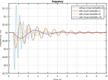
Scenario 1: Step load
In this scenario, %10 step load occurred at t = 1 s. Fig.
on the short-period frequency regulation when secondary frequency control is performed by a convention
figure illustrates that implementing virtual inertia improves the MG dynamic response and reduces the short frequency variation. Moreover,
increasing leads to less short
aberration. In addition, zero regardless of the deal
The same step load variation
compare the performance and efficacy of fuzzy PID and based controllers for frequency regulation. Figure 10 epicts the simulation results considering
This figure demonstrates
controllers ameliorate the dynamic response
compared with classical PID controller. In addition, the settling time, overshoot and
ANFIS-based controller compared controller.
International Journal of Industrial Electronics, Control and Optimization .
© 201The Structure of designed ANFIS
SIMULATION RESULTS
In this part, the effect of the virtual inertia frequency regulation
addition, the performance of conventional PID, fuzzy PID based controllers for frequency regulation considering with and without the virtual inertia
robustness and performance of controllers are gated in the attendance of different disturbances and parametric. In all test scenarios, the conventional PID controller parameters have the same value. Table 4 shows these parameters, which
.
tep load variation
, %10 step load variation
. 9 display the effect of virtual inertia period frequency regulation when secondary frequency control is performed by a convention
that implementing virtual inertia improves the MG dynamic response and reduces the short frequency variation. Moreover, as one can see in figure 9,
leads to less short . In addition, the steady-state
deal of .
The same step load variation is used to evaluate and the performance and efficacy of fuzzy PID and based controllers for frequency regulation. Figure 10 epicts the simulation results considering
demonstrates that fuzzy PID and ANFIS ameliorate the dynamic response
compared with classical PID controller. In addition, the settling time, overshoot and undershoot are reduced by using
based controller compared
© 2019 IECO
The Structure of designed ANFIS-based controller in
SIMULATION RESULTS
virtual inertia on the studied frequency regulation investigated. In addition, the performance of conventional PID, fuzzy PID based controllers for frequency regulation considering with and without the virtual inertia is compared.
robustness and performance of controllers are gated in the attendance of different disturbances and In all test scenarios, the conventional PID controller parameters have the same value. Table 4 shows these parameters, which are obtained u
variation
variation (∆PL = 0.1 pu) is
9 display the effect of virtual inertia period frequency regulation when secondary frequency control is performed by a conventional PID.
that implementing virtual inertia improves the MG dynamic response and reduces the short
as one can see in figure 9, leads to less short-period frequency
state frequency error is
is used to evaluate and the performance and efficacy of fuzzy PID and based controllers for frequency regulation. Figure 10
epicts the simulation results considering equal to 10.
that fuzzy PID and ANFIS ameliorate the dynamic response of the LFC compared with classical PID controller. In addition, the ershoot are reduced by using based controller compared with the fuzzy
IECO 150
based controller in
on the studied investigated. In addition, the performance of conventional PID, fuzzy PID based controllers for frequency regulation is compared. robustness and performance of controllers are gated in the attendance of different disturbances and In all test scenarios, the conventional PID controller parameters have the same value. are obtained using the
= 0.1 pu) is 9 display the effect of virtual inertia period frequency regulation when secondary al PID. This that implementing virtual inertia improves the MG dynamic response and reduces the short-term as one can see in figure 9, frequency frequency error is
International Journal of Industrial Electronics, Control and Optimization .
© 2019 IECO 151B. Scenario 2: Step load variation with parametric uncertainties
In this case, first, each parameter is varied separately, and then the effect of simultaneously changes in the system parameters and modelling errors are considered as a worst case to evaluate the controllers’ robustness. Fig. 11 to Fig. 14 show the effect of parameters change on the frequency regulation when a conventional PID performs the secondary frequency control. Fig. 11 illustrates the MG frequency
response considering Tg andTt variations when is equal
to 3. As one can see the augmentation of the governor and turbine time constant degrade the MG dynamic response. The effect of 50% variation in H and D are presented in Fig. 12
and 13 for equal to 3 and 0.5, respectively. These figures
show that the reduction of load sensitivity coefficient
degrades noticeably the MG dynamic response when is
equal to 0.5. In addition, due to the small amount of the parameter H, its variations have little effect on the MG frequency's behavior. Figure 14 depicts the effect of 50%
variation in R, TFESS and TBESS on the frequency regulation.
This figure shows that the reduction of R decreases the MG
stability and increasing of R leads to more frequency
deviation. Furthermore, due to the small amount of the
parameters TFESS and TBESS, their variations have little effect
on the frequency regulation.
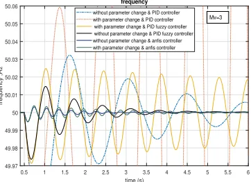
Table 5 shows the intended system parameters variations and modelling errors as a worst case. The simulation results are presented in Fig. 15 and Fig. 16 for this case. As Fig. 15 shown the studied MG become unstable when the controller is conventional PID. Zoomed results are illustrated in Fig. 16. As one can see, in this case, with the Fuzzy-PID controller the studied MG has poor stability. Instead, the proposed control strategy (ANFIS-based controller with implemented virtual inertia) regulates properly the MG frequency and its performance is not much affected by the parameters changes.
TABLE IV. PID CONTROLLER PARAMETERS
P
K
I
K
D
K
2.3 15.19 0.2
Fig. 9. Impact of virtual inertia on the short-period frequency
regulation.
Fig. 10. Performance of different controllers on the short-period
frequency adjustment in the attendance of virtual inertia.
Fig. 11. MG frequency response considering and variations.
Fig. 12. MG frequency response considering H and D variations
for ?= 3
0 1 2 3 4 5 6 7 8 9 10
time (s) 49.75
49.8 49.85 49.9 49.95 50 50.05 50.1 50.15
frequency ,Hz
frequency
without virtual inertia(Mv=0) with virtual inertia(Mv=1) with virtual inertia(Mv=5) with virtual inertia(Mv=10)
0 1 2 3 4 5 6 7 8 9 10
time (s) 49.75
49.8 49.85 49.9 49.95 50 50.05 50.1 50.15
frequency ,Hz
frequency
without virtual inertia
with virtual inertia & Mv=10 & PID controller PID fuzzy controller & Mv=10 anfis controller & Mv=10
0 1 2 3 4 5 6 7 8 9 10
time (s) 49.97
49.98 49.99 50 50.01 50.02
frequency ,Hz
frequency
without parameter change & Mv=3 Tg=+50%
Tg=-50% Tt=+50 Tt=-50
0 1 2 3 4 5 6 7 8 9 10
time (s)
49.97 49.98 49.99 50 50.01 50.02
frequency ,Hz
frequency
without parameter change & Mv=3 H=+50%
International Journal of Industrial Electronics, Control and Optimization .
© 2019 IECO 152Fig. 13. MG frequency response considering H and D variations
for ?= 0.5
Fig. 14. MG frequency response considering R, TFESS and
TBESS variations for ?= 3.
Fig. 15. MG frequency response considering the system
parameters variations and modelling errors shown in table 5.
Fig. 16. Zoomed MG frequency response.
C. Scenario 3: Step load variation with parametric uncertainties without energy storage equipment
In this scenario, the conditions are the same as those in the previous scenario. Nevertheless, in this scenario; energy storage equipment has been removed from the system under study. As can be seen in Figure 17 removing energy storage equipment leads to performance degradation of the conventional PID and Fuzzy PID controllers, where both controllers become unstable. However, using the suggested control scheme, the system frequency is effectively regulated even without energy storage equipment. Furthermore, Fig. 18, which compares the effectiveness of Fuzzy PID and ANFIS-based controllers in this scenario, depicts that the system frequency response remains approximately unchanged with and without energy storage equipment. Fig. 19 illustrates
the performance of the ANFIS-based controller versus Mν
under such conditions. This figure shows that the performance of the ANFIS-based controller is acceptable
even with smallMν =2, but Mν =1leads to MG frequency
instability.
VI.
CONCLUSION
In this paper, to regulate the frequency of studied islanded MG a control scheme is proposed. The proposed control strategy consists of an ANFIS-based controller as secondary frequency control and a rotating-mass-based virtual inertia, implemented in DFIG control system, as an inherent energy storage system. The simulation conclusions demonstrate that using the suggested control strategy the frequency of studied MG can effectively regulate despite removing energy storage equipment, severe system parameters changes and modelling error. three different controllers are implemented in order to achieve good frequency regulation/tracking regardless of the presence of disturbances and parameter variations. In practice,
simple PI&PID controllers are commonly used that providea
poor performance in the presence of serious disturbances and The fuzzy controller is heavily dependent on membership functions. eventually the results reveal that the ANFIS-based controller outperforms other controllers in all aspects such as overshoot, undershoot, steady state error, rise time and settling time.
TABLE V. SYSTEM PARAMETERS CHANGES AND MODELLING
ERRORS
Value Parameter
Value Parameter
+50% ( )
-50% D
+50% ( )
-50% H(s)
+50% ( )
+50% ( )
-50% R
0 1 2 3 4 5 6 7 8 9 10
time (s) 49.94
49.96 49.98 50 50.02 50.04 50.06
frequency ,Hz
frequency
without parameter change & Mv=0.5 H=+50%
H=-50% D=+50 D=-50
0 5 10 15
time (s) 49.97
49.98 49.99 50 50.01 50.02
frequency ,Hz
frequency
without parameter change & Mv=3 R=-50%
R=+50% Tfess=-50% Tbess=+50%
0.5 1 1.5 2 2.5 3 3.5 4 4.5 5
time (s) 49.7
49.8 49.9 50 50.1 50.2 50.3
frequency ,Hz
frequency without parameter change & PID controller with parameter change & PID controller with parameter change & PID fuzzy controller without parameter change & PID fuzzy controller without parameter change & anfis controller with parameter change & anfis controller
Mv=3
0.5 1 1.5 2 2.5 3 3.5 4 4.5 5 5.5 6
time (s) 49.97
49.98 49.99 50 50.01 50.02 50.03 50.04 50.05 50.06
frequency ,Hz
frequency without parameter change & PID controller with parameter change & PID controller with parameter change & PID fuzzy controller without parameter change & PID fuzzy controller without parameter change & anfis controller with parameter change & anfis controller
International Journal of Industrial Electronics, Control and Optimization .
© 2019 IECO 153Fig. 17. MG frequency response without energy storage
equipment and considering the parameters changes.
Fig. 18. Zoomed MG frequency response without energy storage
equipment and considering the parameters changes.
Fig. 19. Performance of ANFIS-based controller versus
?without energy storage equipment and considering the
parameters changes.
R
EFERENCES[1] Y. Fu, Y. Wang, and X. Zhang.: 'integrated wind turbine controller with virtual inertia and primary frequency responses for grid dynamic frequency support' IET Renewable Power Generation., 2017, 11, (8), pp. 1129 – 1137.
[2] M. Heidari., 'Maximum Wind Energy Extraction by Using Neural Network Estimation and Predictive Control of Boost Converter' International Journal of Industrial Electronics, Control and Optimization. Vol. 1, No. 2, pp. 115-120, September (2018).
[3] D. Wang et al., “Participation in primary frequency regulation of wind turbines using hybrid control method”, International Transactions on Electrical Energy Systems, 2018, 28, (5).
[4] M. Fazeli, G. M. Asher, C.Klumpner, and L.Yao, 'Novel integration of DFIG-based wind generators within microgrids' IEEE Trans. Energy Convers., 2011, 26, pp. 840–850.
[5] G. Ramtharan, N. Jenkins, J.B. Ekanayake.: 'Frequency support from doubly fed induction generator wind turbines”. IET Renewable Power Generation'., 2007, 1, (1), pp. 3-9.
[6] N. John and K. Ramesh.: 'Enhancement of load frequency control concerning high penetration of wind turbine using PSO-fuzzy technique', International Journal of Computer Applications., 2013, 69, No 14.
[7] Y. Fu, Y. Wang, X. Zhang.: 'An Integrated Wind Turbine Controller with Virtual Inertia and Primary Frequency Responses for Grid Dynamic Frequency Support', IET Renewable Power Generation., 2017, 11, (8), pp.1129 – 1137.
[8] P.Li, W.Hu, R.Hu, Z.Chen.: 'The Integrated Control Strategy for Primary Frequency Control of DFIGs Based on Virtual Inertia and Pitch Control', Innovative Smart Grid Technologies - Asia, Dec 2016, pp.430 - 435. [9] Q.-C. Zhong and G.Weiss.: 'Synchronverters: Inverters
that mimic synchronous generators', IEEE Transactions on Industrial Electronics., 2011, 58, no. 4, pp. 1259–1267. [10] M. Torres and L. A. C. Lopes.: 'Virtual synchronous
generator control in autonomous wind-diesel power systems', in Proc. IEEE Electrical Power & Energy Conf. (EPEC), 2009, pp. 1–6.
[11] G. Delille, B. Francois, G. Malarange.: 'Dynamic frequency control support: A virtual inertia provided by distributed energy storage to isolated power systems', presented at the IEEE Power and Energy Soc. Innovative Smart Grid Technol. Europe, Oct 2010, pp. 11– 13.
[12] D. Gautam, L. Goel, R. Ayyanar, V. Vittal, and T. Harbour.: 'Control strategy to mitigate the impact of reduced inertia due to doubly fed induction generators on large power systems', IEEE Transactions on Power Systems., 2011, vol. 26, pp. 214–224.
[13] L.-R. Chang-Chien, W.-T.Lin and Y.-C. Yin.: 'Enhancing frequency response control by DFIGs in the high wind penetrated power systems', IEEE Transactions on Power Systems., 2011, 26, pp. 710–718.
[14] Xiaorong. Zhu, Yi Wang, Lie Xu, Xiangyu Zhang, and Heming Li.: 'Virtual inertia control of DFIG based wind turbines for dynamic grid frequency support', IET Conf. Renewable Power Generation, Edinburgh., 2011, pp.16. [15] L. Zeni, I. D. Margaris, A. D. Hansen, P. Sørensen.:
'Virtual inertia for variable speed wind turbines', Wind Energy., 2012, 16, (8), pp. 1225-1239.
[16] Z. Q. Wu and Mizumoto.: 'PID type fuzzy controller and parameter adaptive method', Fuzzy Sets and System., 1996, 78, (1), pp.23-36.
[17] H. Ameli et al., “A fuzzy‐logic–based control methodology for secure operation of a microgrid in interconnected and isolated modes”, International Transactions on Electrical Energy Systems, 2017, 27,(11). [18] S. A. Taher, R. Hematti, A. Abdolalipour, and S. H. Tabei.:
'Optimal decentralized load frequency control using HPSO algorithms in deregulated power systems', American
0.5 1 1.5 2 2.5 3 3.5 4 4.5 5
time (s) 49.4
49.6 49.8 50 50.2 50.4 50.6
frequency ,Hz
frequency conventional PID controller with Energy Storage conventional PID controller without Energy Storage fuzzy PID controller without Energy Storage fuzzy PID controller with Energy Storage anfis controller without Energy Storage anfis controller with Energy Storage
Mv=3
1 2 3 4 5 6 7 8
time (s) 49.96
49.97 49.98 49.99 50 50.01 50.02 50.03 50.04
frequency ,Hz
frequency fuzzy PID controller without Energy Storage fuzzy PID controller with Energy Storage anfis controller with Energy Storage anfis controller without Energy Storage
Mv=3
0.5 1 1.5 2 2.5 3 3.5 4 4.5 5
time (s) 49.992
49.994 49.996 49.998 50 50.002 50.004 50.006 50.008 50.01
frequency ,Hz
frequency
International Journal of Industrial Electronics, Control and Optimization
[19
[20
[21
[22
[23
[24
International Journal of Industrial Electronics, Control and Optimization
Journal of Applied Sciences, 2008,
19] H. Bevrani and P. R. Daneshmand.: 'Fuzzy logic load-frequency control concerning high penetration of wind turbines', IEEE S
20] Bevrani H, Habibi F, Babahajyani P, Watanabe M, Mitani Y.: 'On-line PSO
Transaction on Smart Grids, 2012, 3, (99), 21] K.V. Shihabudheen et al., '
DFIG‐based wind energy system using adaptive neuro fuzzy technique
Energy Systems, 2018, 28, (5). 22] M. F.-M. Arani and E. F. El
virtual inertia in DFIG
generation' ,IEEE Transactions on Power Systems, 2013, 28, (2), pp. 1373
23] J.S.R. Jang.: 'ANFIS: Adaptive network
inference system', IEEE Trans. Sys. Man. Cyb., 1993, 23, (3),
pp.665-24] A. Chikh, A. Chandra.: 'Adaptive neuro cell model',
(6), pp. 679
International Journal of Industrial Electronics, Control and Optimization
Journal of Applied Sciences, 2008,
H. Bevrani and P. R. Daneshmand.: 'Fuzzy logic frequency control concerning high penetration of wind turbines', IEEE Syst. J., 2012, 6, pp. 173
Bevrani H, Habibi F, Babahajyani P, Watanabe M, Mitani line PSO-based fuzzy tuning approach'. IEEE Transaction on Smart Grids, 2012, 3, (99),
K.V. Shihabudheen et al., '
based wind energy system using adaptive neuro fuzzy technique', International Transactions on Electrical Energy Systems, 2018, 28, (5).
M. Arani and E. F. El virtual inertia in DFIG
generation' ,IEEE Transactions on Power Systems, 2013, 28, (2), pp. 1373-1384, 2013.
J.S.R. Jang.: 'ANFIS: Adaptive network
inference system', IEEE Trans. Sys. Man. Cyb., 1993, 23, -685.
hikh, A. Chandra.: 'Adaptive neuro
cell model', IET Renewable Power Generation., 2014, 8, (6), pp. 679-686.
International Journal of Industrial Electronics, Control and Optimization
Journal of Applied Sciences, 2008, 5, pp. 1167 H. Bevrani and P. R. Daneshmand.: 'Fuzzy logic
frequency control concerning high penetration of yst. J., 2012, 6, pp. 173
Bevrani H, Habibi F, Babahajyani P, Watanabe M, Mitani based fuzzy tuning approach'. IEEE Transaction on Smart Grids, 2012, 3, (99),
K.V. Shihabudheen et al., 'Control for grid
based wind energy system using adaptive neuro ', International Transactions on Electrical Energy Systems, 2018, 28, (5).
M. Arani and E. F. El-Saadany, 'Implementing virtual inertia in DFIG-based wind power generation' ,IEEE Transactions on Power Systems, 2013,
1384, 2013.
J.S.R. Jang.: 'ANFIS: Adaptive network
inference system', IEEE Trans. Sys. Man. Cyb., 1993, 23,
hikh, A. Chandra.: 'Adaptive neuro-fuzzy based solar IET Renewable Power Generation., 2014, 8,
International Journal of Industrial Electronics, Control and Optimization
5, pp. 1167-1174. H. Bevrani and P. R. Daneshmand.: 'Fuzzy logic-based
frequency control concerning high penetration of yst. J., 2012, 6, pp. 173–180. Bevrani H, Habibi F, Babahajyani P, Watanabe M, Mitani
based fuzzy tuning approach'. IEEE pp. 1935-1944. Control for grid‐connected based wind energy system using adaptive neuro‐
', International Transactions on Electrical
Saadany, 'Implementing based wind power generation' ,IEEE Transactions on Power Systems, 2013,
J.S.R. Jang.: 'ANFIS: Adaptive network- based fuzzy inference system', IEEE Trans. Sys. Man. Cyb., 1993, 23,
fuzzy based solar IET Renewable Power Generation., 2014, 8,
International Journal of Industrial Electronics, Control and Optimization
based frequency control concerning high penetration of
Bevrani H, Habibi F, Babahajyani P, Watanabe M, Mitani based fuzzy tuning approach'. IEEE
connected ‐ ', International Transactions on Electrical
Saadany, 'Implementing based wind power generation' ,IEEE Transactions on Power Systems, 2013,
based fuzzy inference system', IEEE Trans. Sys. Man. Cyb., 1993, 23,
fuzzy based solar IET Renewable Power Generation., 2014, 8,
electrical engineering main research interest is Intelligent controllers. Authority (KWPA).
in 2008. He is currently an Assistant Professor in Department of Electrical Engineering, Razi University, Kermanshah, Iran. His research interests
control, active power filters, power quality, FACTS Devices and fault tolerant converters.
Electrical Engineering, Razi University, Kermanshah, Iran. His research interests include power system op
and planning, smart grids, demand response,
system, energy hub, load forecasting, and design of electrical and control systems for industrial plant.
International Journal of Industrial Electronics, Control and Optimization
Akbar
Khuzestan, Iran. He received from Jundishapur University of Iran, in 2011, M.
systems
2013. He is currently electrical engineering at Razi
main research interest is Micro grid frequency control, Intelligent controllers. He work
Authority (KWPA).
Shahram Karimi
Iran, in 1972. He received the B.S. degree from University of Tabriz, Tabriz, Iran, in 1995, the M.S. degree from Sharif University of Technology, Tehran, Iran, in 1997, and the Ph.D. degree
the Université Henri Poincaré, Nancy, France, in 2008. He is currently an Assistant Professor in Department of Electrical Engineering, Razi University, Kermanshah, Iran. His research interests include
active power filters, power quality, FACTS Devices and fault tolerant converters.
Hamdi Abdi
1973. He received his B.Sc. degree from Tabriz University, Tabriz, Iran in 1995; M.Sc., and Ph.D. degrees from Tarbiat Modares
Tehran, Iran, in 1999, and 2006, respectively, all in Electrical Engineering. Currently, he is an associate professor in the Department of Electrical Engineering, Razi University, Kermanshah, Iran. His research interests include power system op
and planning, smart grids, demand response,
system, energy hub, load forecasting, and design of electrical and control systems for industrial plant.
International Journal of Industrial Electronics, Control and Optimization .
© 201Akbar karimipouya was born in Andimeshk
Khuzestan, Iran. He received Jundishapur University of in 2011, M.Sc. degree in electrical
s from the Kurdistan University He is currently
Razi University,
Micro grid frequency control,
e works in Khuzestan Water and Power
Shahram Karimi was born in Kermanshah,
Iran, in 1972. He received the B.S. degree from University of Tabriz, Tabriz, Iran, in 1995, the M.S. degree from Sharif University of Technology, Tehran, Iran, in 1997, and the Ph.D. degree all in electrical engineering from niversité Henri Poincaré, Nancy, France, in 2008. He is currently an Assistant Professor in Department of Electrical Engineering, Razi University, Kermanshah, Iran. His include Microgrid voltage and frequency active power filters, power quality, FACTS Devices and
Hamdi Abdi was born in Paveh, Iran, in July
1973. He received his B.Sc. degree from Tabriz University, Tabriz, Iran in 1995; M.Sc., and Ph.D. degrees from Tarbiat Modares
Tehran, Iran, in 1999, and 2006, respectively, all in Electrical Engineering. Currently, he is an associate professor in the Department of Electrical Engineering, Razi University, Kermanshah, Iran. His research interests include power system op
and planning, smart grids, demand response,
system, energy hub, load forecasting, and design of electrical and control systems for industrial plant.
© 2019 IECO
was born in Andimeshk Khuzestan, Iran. He received the B.Sc
Jundishapur University of Technology, degree in electrical from the Kurdistan University He is currently pursuing his Ph
, Kermanshah, Iran Micro grid frequency control, drives and
in Khuzestan Water and Power
was born in Kermanshah, Iran, in 1972. He received the B.S. degree from University of Tabriz, Tabriz, Iran, in 1995, the M.S. degree from Sharif University of Technology, Tehran, Iran, in 1997, and the in electrical engineering from niversité Henri Poincaré, Nancy, France, in 2008. He is currently an Assistant Professor in Department of Electrical Engineering, Razi University, Kermanshah, Iran. His Microgrid voltage and frequency active power filters, power quality, FACTS Devices and
was born in Paveh, Iran, in July 1973. He received his B.Sc. degree from Tabriz University, Tabriz, Iran in 1995; M.Sc., and Ph.D. degrees from Tarbiat Modares University, Tehran, Iran, in 1999, and 2006, respectively, all in Electrical Engineering. Currently, he is an associate professor in the Department of Electrical Engineering, Razi University, Kermanshah, Iran. His research interests include power system optimization, operation and planning, smart grids, demand response,multi carrier energy system, energy hub, load forecasting, and design of electrical and IECO 154
was born in Andimeshk, c. degree Technology, degree in electrical power from the Kurdistan University, Iran in Ph.D. in ran. He’s drives and in Khuzestan Water and Power
was born in Kermanshah, Iran, in 1972. He received the B.S. degree from University of Tabriz, Tabriz, Iran, in 1995, the M.S. degree from Sharif University of Technology, Tehran, Iran, in 1997, and the in electrical engineering from niversité Henri Poincaré, Nancy, France, in 2008. He is currently an Assistant Professor in Department of Electrical Engineering, Razi University, Kermanshah, Iran. His Microgrid voltage and frequency active power filters, power quality, FACTS Devices and