Available Online At www.ijpret.com
INTERNATIONAL JOURNAL OF PURE AND
APPLIED RESEARCH IN ENGINEERING AND
TECHNOLOGY
A PATH FOR HORIZING YOUR INNOVATIVE WORKSENSORLESS BLDC MOTOR CONTROL IN MATLAB SIMULINK
ANKITA A KANEKAR, V. K. JOSEPH
Electronics and Telecommunication Engg. Goa College of Engineering Farmagudi, Goa.
Accepted Date:
27/02/2013
Publish Date:
01/04/2013
Keywords
Brushless DC Motor,
Back EMF ZCD,
Sensorlesscontrol,
Trapezoidal emf.
Corresponding Author Ms. Ankita A Kanekar
Abstract
Brushless DC Motor drives have made a successful entrance into various sectors of industry such as aerospace, automotive and home appliances due to its simple structure. The accurate knowledge of the rotor position is required for good performance of brushless DC motors the need for the rotor angle information in BLDC has been satisfied by use of some form of rotor position sensor. The position sensor used in BLDC drives have the
disadvantages of additional cost, electrical connections,
Available Online At www.ijpret.com
INTRODUCTION
During the last two decades, a lot of
research on sensor less control technique
for BLDC motor has been conducted. Using
of Permanent Magnet in electrical machines
have so many benefits and advantages then
electromagnetic excitation machines these
are zero excitation losses result in high
efficiency, simple construction, low cost less
maintenance and high torque or high
output power per unit volume. Due to high
power to weight ratio, high torque, good
dynamic control for variable speed
applications, absence of brushes and
commutator make Brushless dc (BLDC)
motor, bestchoice for high performance
applications. Due to the absence of brushes
and commutator there is no problem of
mechanical wear of the moving parts.
As well, better heat dissipation property
and ability to operate at high speeds make
them superior to the conventional dc
machine. However, the BLDC motor
constitutes a more difficult problem than its
brushed counterpart in terms of modelling
and control system design due to its
multi-input nature and coupled nonlinear
dynamics. Due to the simplicity in their
control, Permanent-magnet brushless dc
motors are more accepted used in
high-performance applications. In many of these
applications, the production of ripple-free
torque is of primary concern. Therefore, if
the waveforms of the phase back EMF and
phase current are perfectly matched,
torque ripple is minimized. In this paper
finally closed loop speed control is done by
using PID controller under various loading
conditions.
PRINCIPLE OF OPERATION
In conventional BLDC motor during bipolar
operation, at any time across DC bus, two
phases come in series. Only half of the DC
bus voltage is applied to each phase,
resulting in addition of torque constant on
both phases there by achieving high starting
torque. But speed will be limited. To get
higher speed, full DC bus voltage is to be
applied to each phase. This can be achieved
in unipolar operation, where each phase
conducts only in one direction which in turn
reduces the starting torque. order to get
high torque, motor should operate in
bipolar mode and to get high speed motor
should operate in unipolar mode. Shifting of
Available Online At www.ijpret.com operation is achieved based on speed
requirement. In bipolar operation first 3
legs are active and the 4th leg is inactive.
By switching on Q1 and Q4, phase A
conducts in positive direction and phase B
conducts in negative direction. By switching
off Q4 and switching on Q6, a free-wheeling
path is established through phase B, diode
D3, switch Q1 and Phase A as shown in
Figure-1.
By switching off Q1 and switching on Q3
and Q6, the free-wheeling energy in
positive conducting phase A flows through
resistor Rs, D2, phase A, phase C, and Q6, as
shown in Figure2.
SENSORLESS CONTROL OF BLDC MOTOR
Brushless dc (BLDC) motors, with their
trapezoidal electromotive force (EMF)
profile, requires six discrete rotor position
information for the inverter operation.
These are typically generated by Hall- effect
switch sensors placed within the motor.
However, it is a well-known fact that these
sensors have a number of drawbacks. They
increase the cost of the motor and need
special mechanical arrangements to be
mounted. Further, Hall sensors are
temperature sensitive, and hence limit the
operation of the motor. They could reduce
system reliability because of the extra
components and wiring. sosensorless
method is the reliable method used in harsh
environments.There are three independent
methods for determining the Hall
configuration.The selection of which
Available Online At www.ijpret.com
information provided. 1. Hall Based
Commutation Sequence Provided. 2. Back
EMF Waveforms.
1: Hall Based Commutation Sequence
Provided
Either method conveys adequate
information about driving the motor phases
based on Hall Effect sensor states. The
relationship between the Hall Effect sensors
themselves is always consistent. In other
words the Hall Effect sensor sequence seen
in can be found in all motors with
120-degree Hall Effect sensors when the motor
rotates. However, the direction of rotation,
CW or CCW, necessary to produce this
relationship can vary across different
motors. Very often the binary state of the
three Hall Effect sensors will be combined to
create a 3-bit binary word. The mapping
between the Hall states and the three-bit
word. Below the binary word representation
in is tables that represent the states of the
MOSFETs of the half-bridges.
A+ = Phase A high side MOSFET closed
A- = Phase A low side MOSFET closed
B- = Phase B high side MOSFET closed
C- = Phase B low side MOSFET closed
C+ = Phase C high side MOSFET closed
D- = Phase C low side MOSFET closed
If the state of a MOSFET for a particular
Hall state is not defined then it is assumed
to be 0pen. For example during Hall state
1-0-1, MOSFETs A-, B+, C+ and C- are all open.
Below the table of MOSFET states in is a
diagram of the relative voltages through
each motor phase based on the Hall states
(and subsequent MOSFET states). For
instance in Hall state 1- 0-1, the path of the
current begins at the voltage source, flows
through the high side MOSFET of phase A,
through motor winding A, through motor
winding B, through the low side MOSFET of
phase B, and finally to the ground plane.
2 :Back EMF
When a BLDC motor rotates, each winding
generates a voltage known as back
electromotive Force or back EMF, which
opposes the main voltage supplied to the
windings according to Lenz‟s Law. The
commutation time is determined by the
rotor position. Since the shape of back EMF
indicates the rotor position, it is possible to
determine the commutation timing if the
Available Online At www.ijpret.com phase with the phase back EMF. If the zero
crossing of the phase back EMF can be
measured, we will know when to
commutate the current. As mentioned
before, at one time instant, since only two
phases are conducting current, the third
winding is open. This opens a window to
detect the back EMF in the floating winding.
The proposed back emf detection
method describes that, instead of detecting
the zero-crossing point (ZCP) of the
non-excited motor back electromagnetic force
(EMF)or the average motor terminal to
neutral voltage, the true zero-crossing
points of back EMF are extracted directly
from the supply with simple RC circuits and
comparators. In contrast to conventional
methods, the neutral voltage is not needed
and the diode freewheeling currents in the
non-conducted phase are eliminated
completely; therefore, the commutation
signals are more accurate and insensitive to
the common-mode noise. As a result, the
proposed method makes it possible to
achieve good motor performance over a
wide speed range and to simplify the
starting procedure.
A power supply is given to the inverter.
The three phase output of the inverter is
applied to the motors stator windings. From
the supply, voltage divider is connected,
with the RC low pass filter and a zero
crossing detector circuit to produce the back
EMF for three phases. Low pass filter is a
filter that passes low frequency signals but
attenuates higher frequency signals. The
actual amount of attenuation for each
frequency varies from filter to filter. The
Back EMF signals are send to the zero
crossing detector the positional pulse are
produced. A voltage divider (also known as a
potential divider) is a simple linear circuit
that produces an output voltage (Out) that
is a fraction of its input voltage (Vin).
SIMULATION RESULTS
Here simulation is carried out for four cases.
A. Case-1: BLDC with open loop control
When the motor is in standstill conditions
the back EMF will be zero, so rotor Position
cannot be determined by sensorless
method. So initially the motor is started by
applying external gate pulses to the Mosfets
in inverter circuit in proper commutation
Available Online At www.ijpret.com unidirectional torque. The speed of a BLDC
motor is proportional to the voltage applied
to the motor. When using digital control, a
pulse-width modulated (PWM) signal is used
to generate an average voltage.
Figure3 : open loop control for loaded
condition
Figure4 : Table of conclusion
Figure5:open loop speed and torque at
25hz frequency
B. Case-2: BLDC with closed loop PID
control on no
Load Sensorless Method
Figure6 : circuit for close loop control
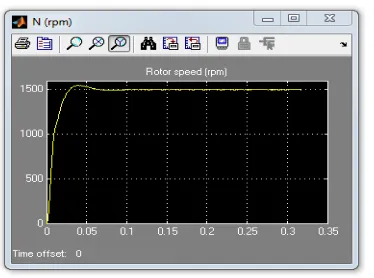
Available Online At www.ijpret.com Figure7 Output waveforms of the speed of
the motor.
Figure-8.Back EMF of the BLDC motor.
Figure-9 Output waveform of the torque of
the motor.
Figure 10.Output waveforms of the
currents.
C. Case-3: BLDC with closed loop PID
control for
Increasing load
Here reference speed is taken as 1500 rpm
the motor reaches the reference speed very
quickly with PID control. Here load torque is
increasing from 0 to 5 N-m at time t = 0.15
Available Online At www.ijpret.com Figure-11 Output waveforms of the speed
of the motor
Figure-12.Back EMF of the BLDC motor.
Figure-13 Output waveform of the torque of
the motor.
Figure-14 Output waveforms of the
currents.
D. Case-4: BLDC with closed loop PID
control for decreasing load
Figure-15Output waveforms of the speed of
Available Online At www.ijpret.com Figure-16 Output waveform of the torque of
themotor.
Figure-17 Output waveform of the torque of
the motor.
CONCLUSIONS
A simple technique to detect back EMF
using RC filter and comparator is defined.
This method provides an amplified version
of the back EMF. Detection of Rotor Position
is determined using Back EMF ZCD.
Simulation results are shown which validate
the suitability of the proposed method.
Simulation of the proposed method is done
by using MATLAB/SIMULINK. The
performance evaluation results show that
this modeling is very useful in studying the
high performance drive before taking up the
dedicated controller design concept for
evaluation of dynamic performance of the
motor. Simulation results are shown for
various loading conditions.
REFERENCES
1. Anand Sathyan, Nikola Milivojevic,
Young-Joo Lee, Mahesh Krishnamurthy, Ali
Emadi,"An FPGA-Based Novel Digital PWM
Control Scheme for BLDC Motor
Drives",IEEE TRANSACTIONS ON
INDUSTRIAL ELECTRONICS,VOL.56, NO. 8,
AUGUST 2009.
2. Cheng-Tsung Lin, Chung-Wen Hung, and
Chih-Wen Liu, Senior
Member,IEEE."Position Sensorless Control
for Four Switch Three-Phase Brushless DC
Motor Drives",IEEE TRANSACTIONS ON
POWER ELECTRONICS, VOL. 23, NO. 1,
JANUARY 2008.
3. Meenal K,K Sobana,A Vanisri.Dr
Available Online At www.ijpret.com POSITION DETECTION AND SPEED CONTROL
OF PMBLDC MOTOR USING VIRUTAL
INSTRUMENTATION",International Journal
of Communications and Engineering
Volume 03 No.3, Issue: 01 March2012.
4. S. Joshuwa, E Sathishkumar, S.
Ramsankar ," Advanced Rotor Position
Detection Technique For Sensorless Bldc
Motor Control ".
5. A.Purna Chandra Rao, Y. P. Obulesh and
Ch. Sai Babu IEEEDepartment, PVPSIT,
Vijayawada, Andhra Pradesh, India IEEE
Department, LBRCE, Maylavaram, India IEEE
Department, JNTUK, Kakinada, Andhra
Pradesh, India, ," Mathematical modeling of
BLDC Motor with closed loop speed control
using PID controller under various loading