Volume 10, Number 2, pp. 147–161. http://www.scpe.org 2009 SCPE
MODEL-DRIVEN ENGINEERING AND FORMAL VALIDATION OF HIGH-PERFORMANCE EMBEDDED SYSTEMS
ABDOULAYE GAMATI´E∗, ´ERIC RUTTEN†, HUAFENG YU‡, PIERRE BOULET‡, AND JEAN-LUC DEKEYSER‡
Abstract. The study presented in this paper concerns the safe design of high-performance embedded systems, specifically dedicated to intensive data-parallel processing as found, for instance, in modern multimedia applications or radar/sonar signal processing. Among the important requirements of such systems are the efficient execution, reliability and quality of service. Unfortunately, the complexity of modern embedded systems makes it difficult to meet all these requirements.
As an answer to this issue, this paper proposes a combination of two models of computation (MoCs) within a framework, called
Gaspard, in order to deal with the design and validation of high-performance embedded systems. On the one hand, the repetitive
MoC offers a powerful expression of the parallelism available in both system functionality and architecture. On the other hand, the synchronous MoC serves as a formal model on which a trustworthy verification can be applied. Here, the high-level models specified with the repetitive MoC are translated into an equational model in the synchronous MoC so as to be able to formally analyze different properties of the modeled systems. As an example, a clock synchronizability analysis is illustrated on a multimedia system in order to guarantee a correct interaction between its components. For the implementation and validation of our proposition, a Model-Driven Engineering (MDE) approach is adopted. MDE is well-suited to deal with design complexity and productivity issues. In our case, the OMG standard MARTE profile is used to model embedded systems. Then, automatic transformations are applied to these models to produce the corresponding synchronous programs for analysis.
Key words: design, high-performance embedded systems, repetitive MoC, synchronous languages, formal validation
1. Introduction. High-performance computing is increasingly becoming important in embedded systems. Very typical application domains are medical imaging or state-of-the-art multimedia devices. Nowadays, multi-media mobile devices such as Personal Digital Assistant (PDA), multimulti-media cell phones and mobile multimulti-media players are ubiquitous. These devices provide many functionalities, such as mp3 playback, camera, video and mobile TV. These features, together with their small size and long power supply make them very attractive in the market. However, they make the design of systems more challenging due to their ever increasing complexity and the need of high quality products in terms of reliability and usability.
In high-performance computing, parallelism plays a central role in order to get efficiency as much as possible. The multimedia application examples mentioned above are characterized by intensive data-parallel processing. Unlike general parallel applications, which are often concerned by code parallelization, intensive data-parallel applications concentrate on the regular data partitioning and access. The data manipulated in these applica-tions are generally represented as multidimensional data structures, e.g. arrays. The highly desirable design approaches for such applications are those providing designers with concepts to suitably represent data manip-ulations, and techniques that trustworthily guarantee important implementation requirements.
The current study addresses this issue by combining technologies for an efficient design of high-performance embedded systems and formal validation of designs.
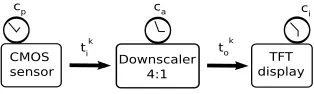
1.1. Motivation example: video processing. Let us consider a video processing system as illustrated in Fig. 1.1: images are captured via a CMOS sensor, then downscaled and displayed on a Thin Film Transistor (TFT) screen. TFT refers to active matrix screens on laptop computers, which offers sharper screen displays and broader viewing angles than does passive matrix. The best known application of TFT is in Liquid Crystal Display (LCD) technology.
Fig. 1.1.A video processing system.
The downscaler transforms a VGA signal (640×480 pixels per frame) into a QVGA signal (320×240 pixels per frame). The required downscaling ratio is therefore 4:1. This operation is interesting when visualizing high
∗CNRS-LIFL, INRIA, Parc de la Haute Borne, Bˆat A, 40 av. Halley, 59650 Vil. d’Ascq, France †INRIA Rhˆone-Alpes, 655 av. de l’Europe, Montbonnot, 38334 Saint-Ismier cedex, France ‡USTL-LIFL, INRIA, Parc de la Haute Borne, Bˆat A, 40 av. Halley, 59650 Vil. d’Ascq, France
quality live video on TFT screen while using low power and real-time previews in recent generation cellular phones. Such phones include several multimedia functionalities, provided by dedicated modules and processors integrated in chips. A more detailed operational view of the whole video processing system is as follows: the CMOS sensor gathers data and sends to the downscaler a flow of pixels, denoted by tk
i. After the receipt of a
sufficient number of pixels, the downscaler transforms these pixels. The resulting pixels denoted by the flowtk o
are sent to the TFT screen, which waits for receiving enough data before displaying images. Each component (sensor, downscaler and display) is assumed to hold a logical clock that defines its activation instants. These clocks are related by affine relations, characterizing the frequencies at which images are received, transformed and displayed. We want to model such a system and analyse how its components’ clocks must be synchronized so that the video can be displayed w.r.t. quality of service requirements.
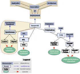
1.2. Rationale and contribution. In order to answer the above demand, we consider the Gaspard
framework (https://gforge.inria.fr/projects/gaspard2), which is dedicated to the design of high-per-formance embedded systems [11]. Gaspard promotes a software/hardware co-design based on model-driven engineering (MDE) [21]. Models are described by using the OMG MARTE (Modeling and Analysis of Real-Time and Embedded systems) standard profile [19], combined with a few native UML concepts. The Hardware Resource Model (HRM) concepts of MARTE enable to describe the hardware part of a system. The Repetitive Structure Modeling (RSM) concepts allow one to describe repetitive structures. Finally, the Generic Component Modeling concepts are used as the base for component modeling.
Fig. 1.2.Embedded system design within theGaspardframework.
In the application functionality part of Fig. 1.2, the focus is put on the expression of data dependencies between components in order to describe an algorithm. The manipulated data are mainly multidimensional arrays. Furthermore, a form of reactive control can be modeled via the notion of execution modes. In the hardware architecture part, similar mechanisms are used to describe regular architectures in a compact way. Regular parallel execution units are more and more present in embedded systems, especially in System-on-Chip (SoCs). HRM is fully used to model these concepts. The association part concerns the allocation of the application functionality onto available execution resources, and the scheduling. The allocation model also takes advantage of the repetitive and hierarchical representation offered by MARTE to express mappings at different granularity levels and in a factorized way.
specific architectures models. This does not facilitate SoC design in which one often needs to program various specialized architectures. InGaspard, the adoptedMARTEprofile is rich enough to enable the description of several types of SoC architectures.
In addition to the previous design aspects,Gaspardproposes a notion ofdeployment specification in order to generate compilable code from a SoC model. The corresponding concepts enablei) to describe a relation between a MARTE representation of each elementary component and a text-based code, e.g. an intellectual property (IP); and ii) to enrich the transformed high-level models with non functional information such as the average execution time or the power consumption for design space exploration. The deployed models are refined towards different technologies for various purposes: formal validation with synchronous languages [2] as shown in this paper, hardware synthesis at the register transfer level (RTL) with VHDL, simulation at transaction level modeling (TLM) in SystemC, high-performance execution in OpenMP Fortran and C. The refinement distinguishes several abstract levels at which the manipulated concepts are characterized by a dedicated metamodel. The transitions from one level to another are defined by automatic model transformations. Among the similar existing co-design frameworks, we can mention those relying on platform-based de-sign (PBD) [20]. Their main idea is to facilitate the design by enabling successive refinements of high level specifications of system functionality and architecture with reusable components so as to rapidly meet the im-plementation requirements of the system. However, the design flexibility may be significantly reduced since the deployment choice is only limited to the available pre-defined components.
In this paper, we define a bridge between the modeling formalism of Gaspard and the synchronous lan-guages so as to get access to formal validation tools. More precisely, we show how models defined with the repetitive model of computation (MoC) of Gaspard are transformed into a set of dataflow equations in syn-chronous languages. This transformation is implemented according to an MDE technique. As an example of analysis that can be applied to the resulting synchronous code, we address the synchronizability between the components of the video processing system shown in Fig. 1.1. For that, we use the affine clock notion of theSignal language [22]. More generally, this paper gives a summary of [14, 13] and extends them with the translation of inter-repetition dependencies during the transformation ofGaspardmodels into synchronous programs. This extension is important for the modeling of control-oriented computations in the repetitive MoC. The implementation of all these aspects is exposed using MDE. The metamodel corresponding to the generated synchronous equational models is detailed as well as the transformation rules. These aspects, which are more related to the implementation are not addressed in [14, 13].
1.3. Outline. In the following, Section 2 describes the basic notions of the repetitive MoC which is used inGaspard to express the parallelism inherent to systems. Section 3 deals with the translation of the models described with the repetitive MoC into synchronous programs. The implementation of this translation using MDE is addressed in Section 4. Section 5 presents how a clock synchronizability analysis can be carried out on the video processing system example, introduced previously by using the synchronous approach. Finally, Section 6 gives concluding remarks.
2. A repetitive model of computation. The repetitive MoC relies on the domain-specific language
Array-Ol [3, 8], which is a mixed graphical-textual functional language enabling to specify both task par-allelism and data parallelism in data intensive applications. In Array-Ol, manipulated data are infinite multidimensional arrays. These arrays are also toroidal because one may sometimes need to represent spatial or frequential dimensions representing physical tori (e.g., hydrophones around a submarine) or some toroidal frequency domains (e.g., obtained with Fast Fourier Transforms). The repetitive MoC is implemented by the RSM package of MARTE.
Fig. 2.1.A model of downscaler inGaspard.
∞is represented by the symbol⋆. The way pixels are extracted from (resp. inserted in) these infinite arrays is described bytilers. The next paragraphs present each specific concept illustrated in the downscaler model.
Overview. The basic specification concepts ofGaspardare summarized by the grammar given below. The notationx:X in this grammar means thatX is the type ofx, and{X}denotes a set of objects of type ofX.
T ask ::= Interf ace;Body (r1)
Interf ace ::= i, o:{P ort} (r2)
P ort ::= id;type;shape (r3)
Body ::= Bodyh|Bodyr|Bodye (r4)
Bodye ::= some f unction f (r5)
Bodyr ::= ti, to :{T iler}; (r;T ask)|
ti, to :{T iler}; (sr;T ask);{Connexion;
→
d;cp} (r6)
Connexion ::= pi, po:P ort (r7)
T iler ::= Connexion; (F;o;P) (r8)
Bodyh ::= {T ask};{Connexion} (r9)
Atomic computation: elementary tasks. An elementary task (rule (r5)) consists of functions that are exe-cuted atomically, e.g. theHfiltertask in Fig. 2.1.
Data-parallelism: repetitive tasks. A repetitive task (rule (r6)) expresses the data-parallelism by replicating a task into severalinstances that consume the elements of its input arrays and produce the elements of output arrays. Each instance executes independently of the others. The sub-arrays consumed and produced by repeated task instances have the same shape. They are referred to as patterns or tiles. For example, in Fig. 2.1 the execution of the repetitive taskHorizontal filterwill lead to the replication of 8 instances of the elementary taskHfilter.
The way the tiles are constructed is defined viatilers (rule (r8)), which are associated with each array (i.e. each edge in the graphical representation). A tiler extracts (resp. stores) tiles from (resp. in) an array based on some information: F is a fitting matrix (how array elements fill the tiles), o is theorigin of the reference tile (for the reference repetition), andP is apaving matrix (how the tiles cover arrays).
The repetition space indicating the number of task instances is itself defined as a multidimensional array with a shape. Each dimension of the repetition space can be seen as a parallel loop and its shape space gives the bounds of the nested parallel loops. In Fig. 2.1, the shape of repetition space in Horizontal filter is (8).
Given a tile, let its reference element denote its origin point from which all its other elements can be extracted. The fitting matrix is used to determine these elements. Their coordinates, represented by ei, are
whole modulo the size of the array (since arrays are toroidal) as follows:
∀i,0≤i<spattern,ei= ref +F×imodsarray (2.1)
wherespatternis the shape of the pattern, sarray is the shape of the array andF is the fitting matrix. Fig. 2.2
illustrates the fitting result for a (2,3)-pattern with the tiling information indicated on the same figure. The fitting index-vector i, indicated in each point-wise element of the pattern, varies between (0
0) and (12). The
reference element is characterized by index-vector (0 0).
Fig. 2.2.Example of paving and fitting scenarios.
Now, for each repetition instance, one needs to specify the reference elements of the input and output tiles. The reference elements of the reference repetition are given by theorigin vector,o, of each tiler. The reference elements of the other repetitions are built relatively to this one. As above, their coordinates are built as a linear combination of the vectors of thepaving matrix as follows:
∀r,0≤r<srepetition,refr=o+P×rmodsarray (2.2)
wheresrepetitionis the shape of the repetition space,P the paving matrix andsarraythe shape of the array. The
paving illustrated by Fig. 2.2 shows how a (2,3)-patterns tile a (6,6)-array. Here, the paving index-vector r, varies between (0
0) and (21).
Task instances may sometimes depend on other task instances in the same repetition space (second alterna-tive of rule (r6)). For example, this happens when computing the sum of the elements of an array by considering the partial sum previously calculated at each step. Such a constraint therefore induces a total execution order on a repetitive task.
In the corresponding rule (r6) of the summary grammar,Connexionrepresents the pair of ports connected by the inter-repetition dependency link: an input ofT askand an output ofT ask. The vector→d specifies the coordinates of the link in the repetition space. For each repetition instance, cp denotes a pattern to be used
as input by the next repetition instance. Initially, cp holds a default value, let us call itdef. There could be
at the same time several inter-repetition dependencies within a task since an instance may require values from more than one instances to compute its outputs. This is why rule (r6) specifies a set of dependency link vectors {Ird}.
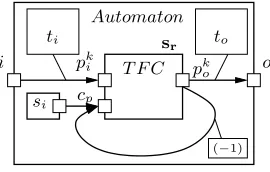
Fig. 2.3 illustrates a simplified notation for a repetitive task with an inter-repetition dependency. This task encodes an automaton. T F C is a transition function that computes, given some input eventspki from its environment (used in the transition conditions) and a current statecp, the value of the next statepko (resulting
from the transition). Here, the dependency vector (−1) indicates that the result pk
o depends on the statecp
computed in the previous step. The initial statesi is given as the default valuedef. This example is a very
i
si ti
o to
(−1)
s r pki
cp
T F C pk
o Automaton
Fig. 2.3. An automaton as a repetitive task with inter-repetition dependency.
Task parallelism: hierarchical tasks. They are represented by hierarchical acyclic graphs in which each node consists of a task, and edges are labelled by the arrays exchanged between these tasks (e.g. Horizontal filter andVertical filterin Fig. 2.1. This naturally leads to hierarchical description of tasks (rule (r9)).
3. Projection of Gaspard on the synchronous model.
3.1. The synchronous languageSignal. The synchronous languageSignal[16] belongs to the family of dataflow languages. Signalhandles unbounded series of typed values (xτ)τ∈N, called signals, denoted asx
and implicitly indexed by discrete time. At a given instant, a signal may be present, at which point it holds a value; or absent and denoted ⊥. The set of instants where a signalxis present represents its clock, noted ^x. Two signalsxandy, which have the same clock are said to besynchronous, notedx ^= y. Aprocess (ornode) is a system of equations over signals that specifies relations between values and clocks of the signals. Aprogram is a process. Signal relies on the following six primitive constructs:
Relations. y:= f(x1,...,xn) def≡ ∀τ ≥ 0 : yτ =6 ⊥⇔ x1τ 6=⊥⇔ ... ⇔ xnτ 6=⊥, and yτ = f(x1τ, ..., xnτ).
Here, y, x1,...,xn are signals and f is a point-wise n-ary relation extended canonically to signals. This construct imposesy, x1,...,xni)to be simultaneously present, andii)to hold values satisfying the equation y:= f(x1,...,xn)whenever they occur.
Delay. y:= x $ 1 init c def≡ ∀τ xτ 6=⊥⇔yτ 6=⊥ and ∀τ > 0: yτ = xk, where k = max{τ′ | τ′ < τ and xτ′ 6=⊥}, y0=c. Here,y, xare signals andcis an initialization constant. This construct imposesi) xandy
to be simultaneously present whileii) ymust hold the value carried byxon its previous occurrence.
Undersampling. y:= x when bwherebis Booleandef≡ ∀τ≥0 :yτ =xτ ifbτ =true, elseyτ=⊥. Here,y, x, b
are signals and b is of Boolean type. This construct imposes i) y to be present only when x is present and bholds the value true, whileii) y must hold the value carried byx at those logical instants. The expression y:= when b is equivalent toy:= b when b.
Deterministic merging. z:= x default y def≡ ∀τ ≥0 : zτ =xτ if xτ 6=⊥, else zτ = yτ. Here, z, y, x are
signals. This construct imposes i)zto be present when eitherxor yare present whileii) zmust always hold the value ofxuppermost, otherwise it takes the value ofy.
Composition. (| P | Q |)def≡ union of the equations ofPandQ, leading to the conjunction of the constraints associated with processesPandQ. It is commutative and associative.
Hiding (or restriction). P where xdef≡ xis local to the processP.
Signal offers a process frame that enables the definition of sub-processes. Sub-processes that are only specified by an interface without internal behavior are considered as external, and may be separately compiled processes.
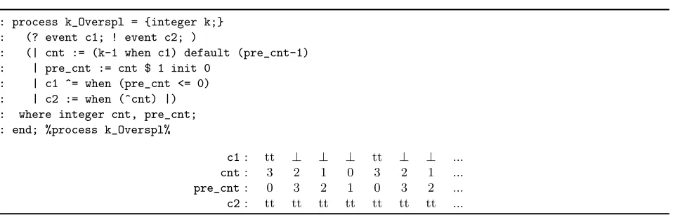
A useful notion of Signal is the oversampling mechanism. It consists of a temporal refinement of a given clockc1, which yields another clockc2, which is faster than c1, meaning thatc2 contains more instants
thanc1.
1: process k_Overspl = {integer k;} 2: (? event c1; ! event c2; )
3: (| cnt := (k-1 when c1) default (pre_cnt-1) 4: | pre_cnt := cnt $ 1 init 0
5: | c1 ^= when (pre_cnt <= 0) 6: | c2 := when (^cnt) |) 7: where integer cnt, pre_cnt; 8: end; %process k_Overspl%
c1: tt ⊥ ⊥ ⊥ tt ⊥ ⊥ ...
cnt: 3 2 1 0 3 2 1 ...
pre_cnt: 0 3 2 1 0 3 2 ...
c2: tt tt tt tt tt tt tt ...
Fig. 3.1.Specification of clock oversampling and an associated execution trace.
There is a graphical syntax of Signal that is very similar to block diagrams. In such a syntax, a box represents a process and a connection between boxes represents the communication of signal values between processes (e.g. see Fig. 3.3 and 3.5).
3.2. Translation ofGaspardinSignal. We present two interpretations ofGaspardmodels inSignal
according to the way the parallelism is considered.
3.2.1. Parallel interpretation. The translation of Gaspard models into synchronous models is struc-tural. It is greatly facilitated by the similarity between Gaspard and Signal since both have a recursive block-diagram structure.
Structural translation. The recursive algorithm following the grammatical structure is as follows, starting with rule (r1) in the previous grammar:
(r1) Each Gaspardtask is represented by aSignalprocess/node, with an interface according to (r2), and a body translating the task body according to (r4).
(r2) Each input and output array of an interface is translated according to (r3).
(r3) Each port is translated as a Signal flow. The infinite dimension of an array can be suitably repre-sented by an infinite flow of arrays of the remaining dimensions. Therefore, we concretely enforce this representation by modelingGaspardarrays into flows of sub-arrays (Fig. 3.2).
(r4) The body is translated according to the appropriate rule, being either an elementary task (r5), a repetitive task (r6), or a hierarchical task (r9).
(r5) An elementary taskE is represented by one equation, aSignalRelationconstruct, defining the outputs by applying a function to the inputs.
(r6) Repetitive tasks are modeled by a compoundSignalnode, where: i)input tilers are transformed according to (r8);ii)the repeated computation is represented by a node with a composition of|r|instances of the node representing the repeated body, obtained by (r1); andiii)output tilers are transformed according to (r8). Fig. 3.3 graphically illustrates theSignalmodel corresponding to a repetitive taskRwith one inputA1 and one outputA2.
When a repetitive task contains a dependency between repetitions, its associated model includes data dependencies between the repetition model instances (Fig. 3.4). The initial value is an input of the first task instance.
(r7) Connexions are translated as assignments between the ports pi andpo.
(r8) Each tiler is represented by a node: for input tilers, this node takes as input the array given by the connexion in (r7), and where each pattern is produced as output, by an equation extracting it from the input array. The indexes for each pattern are obtained by applying the paving and fitting equations (Section 2). Output tilers are represented by a node, where each pattern, given by the connexion in (r7), is inserted in the output array by an equation.
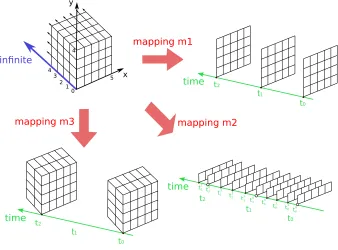
Fig. 3.2.Space-time mapping of a[5,4,∞]-array w.r.t. different granularity levels.
...
... ...
A1
A2 T
T
T
p1 1
p2 1
pk 1
p1 2
p2 2
pk 2
A2[< ind12>] :=p 1 2
A2[< ind2 2>] :=p
2 2
A2[< indk2>] :=pk2 pk1:=A1[< indk1>]
p2
1:=A1[< ind 2 1>] p11:=A1[< ind
1 1>]
Fig. 3.3.Parallel model of a repetitive task.
The above parallel model is meant to be intuitive and simple, and may certainly be optimized. However, the considered optimizations can be quite different according to the intended target operations (e.g. efficient code generation or verification).
3.2.2. Serialized interpretation. While the parallel model fully preserves the data-parallelism of repeti-tive tasks, theserialized model rather sequentializes the repetitions. It is more compact than the parallel model because it only defines one instance of the repeated task in a repetitive task. It features a mono-processor execution of repetitions. More generally, a system will be modeled by combining both parallel and serialized models.
The main difference between the rules in the parallel and serialized interpretations concerns those describing repetitive tasks (r6) and tilers (r8), as follows:
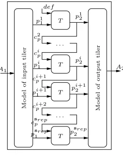
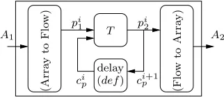
(r6’) Repetitive tasks are modeled by a compound Signalnode (see Fig. 3.5), where: i) the input tilers are encoded by Array to Flow according to (r8’); ii) the repeated task is represented by a single node instanceT obtained by (r1); andiii)the output tilers are encoded byFlow to Array according to (r8’). The synchronous model of a repetitive task containing a dependency between repetitions is similar to the above model. We just need to handle the value transmission between two dependent repetition instances. Repetitions are performed sequentially, one at each logical instant. The value transmission is realized via by using simply a delay or register (Fig. 3.6).
(r8’) Each tiler is represented by a node defined by theArray to Flow andFlow to Array components, which play a central role in the serialized model. Their definition partially relies on the oversampling mecha-nism introduced before.
Let us consider that the incoming array A1 is received at the instants {τi,i∈N} of a given clock c1.
T T T T . . . . . . M o d e l o f in p u t ti le r M o d e l o f o u tp u t ti le r A2 A1 def p1 1
c2p
cip
pi 1
pi1+1
cip+2
csprep
ps1rep ci+1 p
ps2rep pi2+1 pi
2 p1 2
Fig. 3.4.Parallel model of a repetitive task with an inter-repetition dependency.
A1 A2
T
p1
1...pk1 p12...pk2
to Flow) (Array to Array) (Flow
Fig. 3.5.Serialized model of a repetitive task.
is provided with the flow of tiles tj1 and produces the tile flowtj2; the produced tile flow is therefore associated with a clockc2=k↑c1, where 0≤j≤k. The constant integerkis the number of paving
iterations deduced from the repetition space of the task.
For more details about the correctness of the above parallel and serialized interpretations of Gaspard
models, the reader can refer to [14].
4. Implementation of the translation using MDE. Our translation is implemented by a prototype transformation tool relying on MDE. This tool enables to automatically generate synchronous programs from
Gaspardmodels [23].
4.1. Metamodeling. We present the main concepts defined in the metamodels considered during the implementation of our translation.
4.1.1. Repetitive structure modeling in MARTE. A subset of the MARTE profile, called RSM package, is based on our repetitive MoC and is dedicated to the modeling of regular structures (either in application or architecture). All the concepts we focus on are clearly identified in this package. Fig. 4.1 depicts the basic UML stereotypes associated with RSM. TheTilerstereotype, on the bottom right-hand side, comprises theorigin,pavingandfittingattributes for tiling operations.
The package indicates further stereotypes such as the InterRepetitiondependency link presented pre-viously. The Reshape stereotype enables us to express complex link topologies in which the elements of a multidimensional array are redistributed in another multidimensional array. It is a combination of twoTilers, identified with the srcTiler and the targetTilerrelations in Fig. 4.1. A complete description of all these concepts is provided in [19].
T
delay
A2
A1
pi
1 pi2
ci p
(A
rr
ay
to
F
lo
w
)
(F
lo
w
to
A
rr
ay
)
cip+1
(def)
Fig. 3.6.Serialized model of a repetitive task with an inter-repetition dependency.
Fig. 4.1.The RSM package of MARTE.
Signal. The concept of Signals(Fig. 4.2) refers to variables. SignalDeclarationdeclares the name and type of a Signal. ASignal can be a local or an interface variable, respectively captured bySignalLocalDec and SignalInterDec. A declaredSignal can be referenced. The SignalUsagerepresents an operation on a Signal. If aSignal is an array, a SignalUsagecan be an operation on its sub-parts. When such an array is divided into several sub-parts (tiles), it will be associated with the same number of SignalUsage. Every SignalUsagehas an IndexValueSet. Signals are used in both sides of equations. Each side is part of the equation arguments, and aSignalUsageis associated with at least one equationArgument.
Equation. Equations(Fig. 4.3) define relations between signals, considered as itsArguments. ButSignals andArgumentsdo not have a direct relation; SignalUsagesplay this intermediate role. AnEquationhas an EquationRightPartand at most one EquationLeftPart. The latter hasArgumentsasEquationoutputs.
EquationRightPartis either an ArrayAssignmentor a nodeInvocation. ArrayAssignmenthas
Arguments, and indicates that theEquationis an array assignment. Invocationis a call to anotherNode, where FunctionIdentifierindicates the called function. An Invocation may have an ordered list of Arguments, which are used as the inputs of the function. Equationscan be assembled in an EquationSystem.
Node. Functionalities are modeled asNodes(see Fig. 4.4). Such aNodehas anInterface,
aLocalDeclaration, someNodeVariablesand anEquationSystem.NodeVariableis the container ofSignals andSignalUsages.
<<metaclass>> IndexValueSet <<metaclass>> SignalDeclaration <<metaclass>> SignalUsage <<metaclass>> Signal <<metaclass>> Argument <<metaclass>> IndexValue +signalUsage 1 +arguments 0..* +indexValue {ordered} 1..* +owner +signal 1 +signal 1 +declaration 1 +indexValueSet 0..1 +signalUsage 1
Fig. 4.2.Signalpart of our synchronous metamodel.
<<metaclass>> Argument <<metaclass>> Invocation <<metaclass>> FunctionIdentifier <<metaclass>> Equation <<metaclass>> EquationRightPart <<metaclass>> ArrayExpression <<metaclass>> EquationLeftPart <<metaclass>> Node +arguments {ordered} 1..* +equationLeftPart 0..1 +arguments 1..* +arrayExpression 0..1 +arguments {ordered} 0..* +invocation 0..1 +left 0..1 +owner +invocatedFunction 1 +invocation +instantiatedNode 1 +right 1 +owner
Fig. 4.3.Equationpart of our synchronous metamodel.
<<metaclass>> SignalInterDec <<metaclass>> Interface <<metaclass>> Node <<metaclass>> SignalLocalDec <<metaclass>> LocalDeclarations <<metaclass>> NodeVariables <<metaclass>> EquationSystem +nodeVariables 0..1 +owner 1 +interface 0..1 +owner 1 +equations 1 +owner 1 +localNodes 0..* +localDefinitions 0..1 +owner 1 +parameters {ordered} 0..* +interface 1 +outputs {ordered} 0..* +interface 1 {ordered} +locals 1..* +owner 1 {ordered} +inputs 0..* +interface 1
<<metaclass>>
SynchronousEquationModule
<<metaclass>>
Node
<<metaclass>>
Implementation
<<metaclass>>
CodeFile +mainInstance
1 0..*
+ip
+owner
+nodes 1..* +owner 1
+codeFiles 0..*
+owner
Fig. 4.5.Modulepart of our synchronous metamodel.
4.2. Transformations towards synchronous programs. The transformation ofGaspardmodels into synchronous programs consists of two steps (Fig. 4.6):
1. transformation of models specified with MARTE into synchronous models; 2. code generation from synchronous models obtained from the first step.
Fig. 4.6.From MARTE models to synchronous dataflow programs.
Our transformation rules are represented through a tree structure (Fig. 4.7). There are mainly twenty transformation rules. The root rule is GModel2SModel. It transforms a Gaspard model into a synchronous program by recursively calling its sub-rules: GTiler2SNode devoted to the transformation of tilerconnectors, GApplication2SNode devoted to the transformation of the different Task notions of Gaspard, etc. A more complete presentation of all rules is given in [23].
Fig. 4.7.Hierarchy of the transformation rules
The above transformation rules as well as the code generation are achieved within theEclipseModeling Framework (EMF) [9]. Gaspard models are exported as EMF models, which are then transformed into
EMF synchronous equational models, used finally to generate synchronous programs. This transformation chain has been implemented by using some specific technologies.
TheMoMoTEtool (MOdel to MOdel Transformation Engine), based onEMF, is aJavaframework that enables to perform model to model transformations. It is composed of an API and an engine. It takes input models that conform to some metamodels and produces output models that conform to other metamodels. A transformation byMoMoTEis composed of hierarchical rules. These rules are integrated into anEclipse plu-gin that is automatically invoked during model transformations.
code generation tool. These templates are used to generateJavaimplementation classes. MoCodEconsists of anAPIwith an engine that performs model to text transformation. It takes a set of models as inputs. Then, its engine recursively takes out elements from input models and executes a correspondingJavaimplementation class on them. TheseJavaclasses finally generate the target code. The size of our implemented transformation chain is about 5.103lines of Java code.
5. Validation of design properties. We present a typical use of the analysis techniques and tools associated with synchronous languages to analyze the video processing system introduced in Section 1, via a corresponding generated code. The addressed issue specifically concerns clock synchronizability between the system components in order to satisfy some non functional requirements.
5.1. Clock synchronizability analysis with the synchronous technology. Let us denote by cp, ca
andci the respective logical clocks of the sensor, the downscaler and the display. They respectively represent
the pixel production rate in the sensor, the bloc computation frequency within the downscaler, and the image production rate on the display. The whole model works as follows: the sensor produces its output data pixel by pixel; the downscaler periodically performs an operation whenever it receives from the sensor a fixed number of pixels; and the TFT screen periodically displays an image whenever it receives from the downscaler a fixed number of blocs of transformed pixels. A step in cp,ca andci corresponds to the production of respectively a
single pixel by the sensor, a transformed block of pixels by the downscaler, and an image by the TFT display. From the point of view of Gaspard, the clock steps associated with a component correspond to its paving iterations. We therefore derive the following constraints between above logical clocks:
• C1: cais an affine undersampling ofcp, i.e.,cp
(1,φ1,d1)
→ ca;
• C2: ciis an affine undersampling ofca, i.e.,ca
(1,φ2,d2)
→ ci;
Now, let us consider a specification requirement of the video display functionality, consisting of a constraint on the actual production rate, noted c′
i, of displayed images in the cell phone. This constraint, denoted by C3, states a relation between the pixel production ratecp and c′i as follows: cp
(1,φ3,d3)
→ c′
i. Then, we need to
guarantee the compatibility of this new constraint with the previous set of constraints{C1, C2}. I.e., we want
to establish a synchronizability relation between clocksc′
i andci w.r.t. {C1, C2, C3}. This will ensure that the
expected rate of the TFT display ci, which depends on the rate of the downscaling process ca, satisfies the
requirement.
This issue cannot be addressed by only using the usual definition of clock synchronization in synchronous languages. Instead, we consider affine clock systems in order to define under which condition c′
i and ci are
synchronizable. So, from C1, C2 and C3, this synchronizability property is checked by using the following
property, which has been proved and implemented in theSignalcompiler:
c′iandci are synchronizable ⇔
(
φ1+d1φ2=φ3 d1d2=d3
(5.1)
This issue is solved quite easily with synchronous models while it is not possible withGaspardonly. The result of this analysis can be used to adjust the paving iteration parameters of the downscaler model so as to satisfy the non functional requirements imposed on the whole system.
In [22], Smarandacheet al. combine the Alphalanguage and the synchronous languageSignal to design and validate embedded systems by defining affine clocks relations. Our approach differs from this work in that we propose a synchronous model of a whole data-parallel application instead of describing only its clock information as it is the case with [22]. As a result, our model allows us to address both functional and non functional properties of the application using the synchronous technology. Another similar work concerns the design ofn-synchronous Kahn networks [7] in which authors consider theLucid Synchronelanguage in order to address the correct-by-construction development of high performance stream-processing applications. This work also defines clock synchronizability properties that can be applicable to Gaspard models specified in
5.2. Other analyses. In addition to the above clock relation analysis, the synchronous technology also enables to address further model design properties imposed by theGaspardunderlying specification formalism,
Array-Ol, as shown in [14]: single assignment, functional determinism, absence of cyclic data-dependencies. The compilers of synchronous languages provide us with very efficient data-dependency analysis techniques to address such properties.
Furthermore, in [24], we dealt with both functional and non functional properties of an application case study, consisting of the multimedia processing module of a cellular phone. We applied theSigalimodel-checker (from the synchronous technology) [17] to synchronous programs generated fromGaspard models extended with controlled computations specification [12].
6. Concluding remarks. In this paper, we presented an approach to deal with the reliable design of high-performance embedded systems by combining the repetitive and synchronous models of computation. While the former model suits for the adequate expression of data-parallelism and task parallelism in such systems, the latter model allows one to reason about critical design properties of the systems. These models of computation are respectively implemented in theGaspardand synchronous design frameworks. We showed howGaspard
models can be translated into synchronous models in order to formally check the correctness of the systems initially designed with the MARTE standard profile in Gaspard. Here, we illustrated a synchronizability analysis on a simple system example by using the synchronous technology. Further design correctness properties can be also straightforwardly checked with the same technology as it has been exposed in [14, 24].
REFERENCES
[1] E. Allen, D. Chase, J. Hallett, V. Luchangco, J.-W. Maessn, S. Ryu, G. S. Jr., and S. Tobin-Hochstadt,The
Fortress Language Specification Version 1.0 Beta, tech. report, Sun Microsystems, Inc., Mar. 2007.
[2] A. Benveniste, P. Caspi, S. Edwards, N. Halbwachs, P. Le Guernic, and R. de Simone,The synchronous languages
twelve years later, Proceedings of the IEEE, 91 (2003), pp. 64–83.
[3] P. Boulet,Formal Semantics ofArray-Ol, a Domain Specific Language for Intensive Multidimensional Signal Processing,
tech. report, INRIA, France, March 2008. available online athttp://hal.inria.fr/inria-00261178/fr.
[4] C. Brunette, J.-P. Talpin, A. Gamati´e, and T. Gautier,A metamodel for the design of polychronous systems, Journal
of Logic and Algebraic Programming, (2009).
[5] D. Callahan, B. Chamberlain, and H. Zima,The Cascade High Productivity Language, in 9th International Workshop on
High-Level Parallel Programming Models and Supportive Environments, IEEE Computer Society, Apr. 2004, pp. 52–60.
[6] P. Charles, C. Grothoff, V. Saraswat, C. Donawa, A. Kielstra, K. Ebcioglu, C. von Praun, and V. Sarkar,X10:
an object-oriented approach to non-uniform cluster computing, in 20th annual ACM SIGPLAN conference on Object oriented programming, systems, languages, and applications, New York, NY, USA, 2005, ACM Press, pp. 519–538.
[7] A. Cohen, M. Duranton, C. Eisenbeis, C. Pagetti, F. Plateau, and M. Pouzet,N-sychronous Kahn networks, in ACM
Symp. on Principles of Programming Languages (PoPL’06), Charleston, South Carolina, USA, January 2006.
[8] A. Demeure and Y. Del Gallo,An array approach for signal processing design, in Sophia-Antipolis conference on
Micro-Electronics (SAME’98), SoC Session, France, Oct. 1998.
[9] Eclipse,Eclipse Modeling Framework. http://www.eclipse.org/emf.
[10] ,EMFT JET. http://www.eclipse.org/emft/projects/jet.
[11] A. Gamati´e, S. Le Beux, E. Piel, A. Etien, R. Ben Atitallah, P. Marquet, and J.-L. Dekeyser,A model driven
design framework for high performance embedded systems, Research Report 6614, INRIA, France, August 2008. http: //hal.inria.fr/inria-00311115/en.
[12] A. Gamati´e, E. Rutten, and H. Yu,A Model for the Mixed-Design of Data-Intensive and Control-Oriented Embedded
Systems, Tech. Report 6589, INRIA, France, July 2008. http://hal.inria.fr/inria-00293909/en.
[13] A. Gamati´e, ´E. Rutten, H. Yu, P. Boulet, and J.-L. Dekeyser,Modeling and formal validation of high-performance
embedded systems, in 7th International Symposium on Parallel and Distributed Computing (ISPDC’2008), Krakow, Poland, IEEE Computer Society, july 2008, pp. 215–222.
[14] A. Gamati´e, E. Rutten, H. Yu, P. Boulet, and J.-L. Dekeyser,Synchronous Modeling and Analysis of Data Intensive
Applications, Eurasip Journal on ES, 2008 (2008).
[15] N. Halbwachs, Y. Proy, and P. Roumanoff,Verification of real-time systems using linear relation analysis, Formal
Methods in System Design, 11 (1997), pp. 157–185.
[16] P. Le Guernic, J.-P. Talpin, and J.-C. Le Lann, Polychrony for System Design, Journal for Circuits, Systems and
Computers, 12 (2003), pp. 261–304.
[17] H. Marchand, P. Bournai, M. L. Borgne, and P. L. Guernic,Synthesis of discrete-event controllers based on the Signal
environment, Discrete Event Dynamic System: Theory and Applications, 10 (2000), pp. 325–346.
[18] Message Passing Interface Forum,MPI Documents.www.mpi-forum.org/docs/docs.html.
[19] Object Management Group,A UML profile for MARTE, 2007. http://www.omgmarte.org.
[20] A. Sangiovanni-Vincentelli,Quo Vadis, SLD? Reasoning About the Trends and Challenges of System Level Design,
Pro-ceedings of the IEEE, 95 (2007), pp. 467–506.
[22] I. Smarandache, T. Gautier, and P. Le Guernic,Validation of mixed Signal-Alpha real-time systems through affine calculus on clock synchronisation constraints, in World Congress on Formal Methods (2), 1999, pp. 1364–1383.
[23] H. Yu, A. Gamati´e, E. Rutten, and J.-L. Dekeyser,Embedded Systems Specification and Design Languages, Selected
Contributions from FDL’07 Series: Lecture Notes Electrical Engineering, Vol. 10, ISBN: 978-1-4020-8296-2, Villar Eu-genio (Ed.), Springer Verlag, 2008, ch. 13: Model Transformations from a Data Parallel Formalism towards Synchronous Languages.
[24] H. Yu, A. Gamati´e, E. Rutten, and J.-L. Dekeyser, Safe design of high-performance embedded systems in an mde
framework, Innovations in Systems and Software Engineering, 4 (2008), pp. 215–222.
Edited by: Marek Tudruj, Dana Petcu Received: February 6th, 2009