Available Online at www.ijpret.com 14
INTERNATIONAL JOURNAL OF PURE AND
APPLIED RESEARCH IN ENGINEERING AND
TECHNOLOGY
A PATH FOR HORIZING YOUR INNOVATIVE WORK
FAILURE ANALYSIS AND PROCESS IDENTIFICATION FOR A CRANKSHAFT: A
REVIEW
PACHPANDE JE1, VERMA D2
1. P. G. Student, Mech Engg Deptt, Pdm. Dr. V. B. Kolte C. O. E. Malkapur, India. 2. Asso. Prof. Mech Engg Deptt, Pdm. Dr. V. B. Kolte C. O. E. Malkapur, India.
Accepted Date: 05/10/2014; Published Date: 01/11/2014
\
Abstract:Crankshaft is one of the most important moving parts in internal combustion engine. Crankshaft is
a large component with a complex geometry in the engine, which converts the reciprocating displacement of the piston into a rotary motion with a four link mechanism. The paper details the optimization options, their combination under a set of defined constraints and a comparison between the original forged steel crankshaft and the final optimized forged steel component. The main objective of this analysis was to optimize the weight and manufacturing cost of the forged steel crankshaft, which not only reduces the final production cost of the component, but also results in a lighter weight crankshaft which will increase the fuel efficiency of the engine. Geometry, material, and manufacturing processes were optimized using different geometric constraints, manufacturing feasibility and the first step in the optimization process was weight reduction of the component considering dynamic loading. This required the stress range under dynamic loading not to exceed the magnitude of the stress range in the original crankshaft.
Keywords: Design of Crankshaft, Optimization Procedure, failures, Causes of Failures for Crankshaft
Corresponding Author: MR. J. E. PACHPANDE
Access Online On:
www.ijpret.com
How to Cite This Article:
Pachpande JE, Verma D; IJPRET, 2014; Volume 3 (3):14-25
Available Online at www.ijpret.com 15 INTRODUCTION
Crankshaft
Crankshaft is among the largest components in internal combustion engines. It is employed in different types of engines, from small one cylinder lawn-mowers to large multi-cylinder diesel engines. Crankshaft is one of the most critically loaded components and experiences cyclic loads in the form of bending and torsion during its service life. This review is performed for optimization of crankshaft by considering various materials used for manufacturing of crankshaft, various manufacturing process used for manufacturing of crankshaft and opportunities available for optimization by various geometric changes in shape of crankshaft. Amongst all materials used for manufacturing of crankshaft the best material is selected and is manufactured by method which is most suitable and will reduce the cost of production. So now the various optimization studies are made on crankshaft made by the selected material manufactured method considered.
Optimization of Crankshaft
The main objective of optimization is to reduce the cost, weight or improve the geometry of component bye effective utilization of resources available. For optimization of crankshaft various studies have been made on material selection and manufacturing process of crankshaft, it is found crankshafts are typically manufactured from forged steel, nodular cast iron and austempered ductile iron (ADI). When forged steels are compared to cast iron and alloyed ductile iron used in crankshafts, the fatigue properties of forged steels are generally found to be better that that of cast iron. Also it is found that by using micro alloy steel it is possible to reduce the cost of production. Therefore replacement of conventional crankshaft by forged steel shaft will also result in optimization of cost. Therefore the optimization of forged steel crankshaft has been made in many research works, which is discussed in this seminar.
Available Online at www.ijpret.com 16 Material for Crankshaft
The major crankshaft material and manufacturing processes currently in use are forged steel, nodular cast iron and austempered ductile iron (ADI). Chatterley and Murrell compared fatigue strength of crankshafts made of forged steel, ductile iron and austempered ductile iron by conducting bending fatigue tests. Tests were performed by Chatterley and Murrell on nitrided 1% chromium/molybdenum forged steel, fillet-rolled ductile iron with 700 MPa tensile strength and 2% elongation, and fillet rolled ADI (the austempered version of the ductile iron used). All crankshafts were designed to operate within a 4 cylinder turbo-charged diesel engine. The fatigue tests were carried out on a constant amplitude mechanical stroking machine. The crankshafts were firmly clamped with split clamping blocks across two main bearing journals, with the bending moment being applied by means of a moment arm bolted onto an adapter press-fitted onto either the front (nose) or flywheel end of the shafts. Fatigue strength at ten million cycles of the rolled ADI crankshaft was found to be inferior to the forged steel crankshafts. However, the ADI showed better fatigue strength than ductile iron. So in this project we discussed experimental and modal analysis of 3 cylinder petrol engine forged steel crankshaft.
LITERATURE SURVEY
R.M. Metkar, et al [1], review on fatigue life of crankshaft is to investigate the behavior of crankshaft under complex loading conditions. Automobile industries are always interested to develop a new product which will be innovative and fulfill market expectations. Various other factors also play important role in mechanical fatigue failure of crankshaft, such as, misalignment of crankshaft on assembly, improper journal bearing, and vibration due to some problem with main bearing or due to high stress concentration caused by incorrect fillet size, oil leakage, and overloading, high operating oil temperature. Heat and stresses during contact bearing with repetition of heating and cooling would eventually create thermal fatigue cracks and it will propagate with time.
Available Online at www.ijpret.com 17
Meng et al. [3] discussed the stress analysis and modal analysis of a 4 cylinder crankshaft. FEM software ANSYS was used to analyze the vibration modal and distortion and stress status of crank throw. The relationship between frequency and the vibration modal was explained by the modal analysis of crankshaft. This provides a valuable theoretical foundation for the optimization and improvement of engine design. Maximum deformation appears at the center of the crankpin neck surface. The maximum stress appears at the fillet between the crankshaft journal and crank cheeks, and near the central point journal. The crankshaft deformation was mainly bending deformation was mainly bending deformation under the lower frequency. Maximum deformation was located at the link between main bearing journal and crankpin and crank cheeks. So, the area prone to appear the bending fatigue crack.
Jian et al.[4] analyzed three dimensional model of 380 diesel engine crankshaft. They used ProE and ANSYS as FEA tools. First of all, the 380 diesel engine entity crankshaft model was created by Pro E software. Next, the model was imported to ANSYS software. Material properties, constraints boundary conditions and mechanical boundary conditions of the 380 diesel engine crankshaft were determined. Finally, the strain and the stress figures of the 380 diesel crankshaft were calculated combined with maximum stress point and dangerous area. This article checked the crankshaft’s static strength and fatigue evaluations. That provided theoretical foundation for the optimization and improvement of engine design. The maximum deformation occurs in the end of the second cylinder balance weight.
Bin et al.[5] investigated the vibration model of 480 diesel crankshaft and the stress analysis of crankpin. Three dimensional models of 480 diesel engine crankshaft and crankpin were created through Pro E software. Finite element analysis software ANSYS was used to analyze the vibration model and the distortion and the stress status of the crankpin. This explains the relationship between the frequency and the vibration model. Stress analysis of crankpin provides the maximum deformation and maximum stress point. The crankshaft deformation was mainly bending deformation under lower frequency. The maximum deformation was located at the link between main bearing journal and crankpin and crank cheeks. So the bending crack was prone to appear at this area. The maximum deformation appears the bottom of crank cheek. The maximum stress appears at the transition radius of crank cheek and connecting rod journal.
Available Online at www.ijpret.com 18
steel, from similar single cylinder four stroke engines. Finite element analyses were performed to obtain the variation of stress magnitude at critical locations. The dynamic analysis was done analytically and was verified by simulations in ANSYS. Results achieved from aforementioned analysis were used in optimization of the forged steel crankshaft. Geometry, material and manufacturing processes were optimized considering different constraints, manufacturing feasibility and cost. The optimization process included geometry changes compatible with the current engine, fillet rolling and results in increased fatigue strength and reduced cost of the crankshaft, without changing connecting rod and engine block.
Yingkui and Zhibo [7]established three dimensional model of a diesel engine crankshaft by using Pro E software. Using ANSYS analysis tool, the finite element analysis for the crankshaft was conducted under extreme operation conditions and stress distribution of the crankshaft was presented. The crank stress change model and the crank stress biggest hazard point were found by using finite element analysis, and the improvement method for the crankshaft structure design was given. This shows that the high stress region mainly concentrates in the Knuckles of the crank arm & the main journal, and the crank arm and the connecting rod journal, which is the area most easily broken.
Bhumesh J. Bagde and Laukik Raut [8] studied the Structural and Fatigue Analysis of Single Cylinder Engine Crank Shaft the paper deals with, the problem occurred in single cylinder engine crank shaft.
Gu Yingkui, Zhou Zhibo [9] has been discussed a three-Dimensional model of a diesel engine crankshaft were established by using PRO/E software and analytical ANSYS Software tool, it shows that the high stress region mainly concentrates in the knuckles of the crank arm & the main journal and the crank arm & connecting rod journal, which is the area most easily broken.
ABOUT CRANKSHAFT
Available Online at www.ijpret.com 19
effective manufacturing plan. Following preparation of manufacturing plan and simulating the processes, a prototype component should be manufactured and tested to verify the design requirements. Crankshafts are typically manufactured by casting and forging processes Manufacturing by forging has the advantage of obtaining a homogeneous part that exhibits less number of micro structural voids and defects compared to casting. In addition, directional properties resulting from the forging process help the part acquire higher toughness and strength in the grain-flow direction. While designing the forging process for crankshaft, the grain-flow direction can be aligned with the direction of maximum stress that is applied to the component (along the axis of the shaft and related to bending).
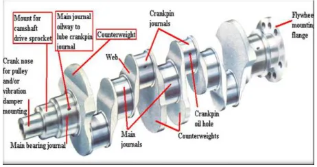
Fig 3.1: Crankshaft nomenclature
Heat Treatment
Flame and Induction Surface Hardening
These are the surface hardening methods for steel having 0.3 to 0.5% carbons without the use of special compounds or gases. The basic principle is to rapidly apply heat to the surface followed by only water quenching. As it is heated locally instead of heating the entire mass, the hardening is greatly reduced and distortion of the journal is avoided.
Flame hardening is carried out by oxyacetylene flame at the surface layer temperature between
9930K and 11730 K. The surface temperature depends on the carbon content equivalent of the
different alloying elements in the steel. The heating process is followed by a water-jet quenching operation. Since the actual period for heating and cooling is critical, it is predetermined and is mostly automatically controlled.
high-Available Online at www.ijpret.com 20
frequency current. This induces circulating eddy currents in the journal surface thereby rising of its temperature and heat is mostly confined to the outer surface of the journals. In this process the higher the frequency of the current, the closer the heat is to the skin. The current is automatically switched off when the required temperature is attained and the surface is simultaneously quenched by water jet, which passes through holes in the induction block.
Nitriding Surface-Hardening Process
In this process the journals are heated to 773 K for a predetermined time in an ammonia gas atmosphere, so that the nitrogen in the gas is absorbed into the surface layer. The alloying elements such as chromium, aluminium, and molybdenum, present in the steel, from hard nitrides. Aluminium nitrides form an intensely hard shallow case. Chromium nitrides diffuse to a greater depth than aluminium nitrides. The molybdenum increases harden ability, gives grain refinement, and improves the toughness of the core. This process can use directly the journals ground to their final size as there is no quenching after nitriding thereby avoiding distortion unlike other surface-hardening processes. The slow rate of penetration of the surface makes the cost of the process high for example; it takes 20 hours to produce a case depth of about 0.2 mm.
Carbo Nitriding Surface-Hardening Process
Available Online at www.ijpret.com 21 Forging Process and the Influencing Parameters
Forging is the term for shaping metal by plastic deformation. Cold forging is done at low temperatures, while conventional hot forging is done at high temperatures, which makes metal easier to shape. Cold forgings are various forging processes conducted at near ambient temperatures, such as bending, cold drawing, cold heading, coining, and extrusion to produce metal components to close tolerances and net shape.
Warm forging is a modification of the cold forging process where the work piece is heated to a temperature significantly below the typical hot forging temperature, ranging from 500º C to 750º C Compared with cold forging, warm forging has the potential advantages of reduced tooling loads, reduced press loads, increased steel ductility, elimination of need to anneal prior to forging, and favorable as-forged properties that can eliminate heat treatment. The use of the lower temperatures in cold and warm forging processes provides the advantages of reducing and even substantially eliminating the harmful scale or oxide growth on the component as well as enabling the component to be produced to a high dimensional accuracy.
Despite these advantages, cold and warm forging processes have the limitations of close tolerance and net shape of the final component with the work piece. Hot forging is the plastic deformation of metal at a temperature and strain rate such that recrystallization occurs simultaneously with deformation, thus avoiding strain hardening. Since crankshafts have complex geometries, warm and cold forging of the component is not possible. Therefore, crankshafts are manufactured using the hot forging process. In impression (or closed die) hot forging two or more dies are moved toward each other to form a metal billet, at a suitable temperature, in a shape determined by the die impressions. These processes are capable of producing components of high quality at moderate cost. Forgings offer a high strength to weight ratio, toughness, and resistance to impact and fatigue, which are important factors in crankshaft performance. In closed die forging, a material must satisfy two basic requirements: (a) The material strength (or flow stress) must be low so that die pressures can be kept within the capabilities of practical die materials and constructions, and (b) The capability of the material to deform without failure (forgeability) must be sufficient to allow the desired amount of deformation.
Available Online at www.ijpret.com 22
friction and cooling effects at the material interface and (c) the complexity of the forging shape. A multi-cylinder crankshaft is considered to have a complex geometry, which necessitates proper work piece and die design according to material forge ability and friction to have the desired geometry.
Fig 3.2: crankshaft work piece
Failures in Crankshaft
The most common types of failure are
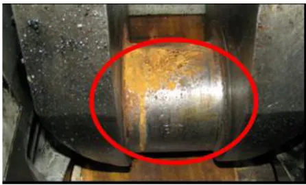
Available Online at www.ijpret.com 23 Figure 3.4 Bending of crankshaft
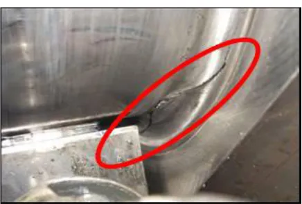
Figure 3.5 Cracking of this crankshaft between the crank pin and the crank web.
Causes of Failures
The most common causes for crankshaft failures are below:
1. Loss of effective lubrication. This can be due to contaminated lube oil, failed lube oil pumps, poor quality or incorrect specification lube oil.
2. Over speeding of engines, or long term operation in a critical or forbidden rev range.
3. Faulty crankshaft damper, designed to remove excessive vibration from the crankshaft. Failure of proper operation can lead to excessive crankshaft vibration and fatigue.
4. Engine power imbalance leading to fatigue failure, cyclic loading. This can be caused by poor maintenance or monitoring of engine power, or even poor quality fuel.
Available Online at www.ijpret.com 24
6. Bearing misalignment, this can be detected early with proper crankshaft deflection measurement.
7. Design faults, a common problem as more licenses are passed out to new shipyards. Incorrect or blatant ignorance of material compositions or poor manufacture of crankshaft can lead to early failure.
8. Overloading of engine.
9. For propulsion machinery, grounding, and/or fouling of the propeller.
CONCLUSION
The optimization process was categorized indifferent stages and paper concludes with the sufficient reduction in weight and ultimately cost. The optimization resulted in an 18% weight reduction of the forged steel crankshaft. This was achieved by changing the dimensions and geometry of the crank counterweights while maintaining dynamic balance of the crankshaft. The optimization that was developed did not require any changes to the engine block or connecting rod. After each optimization step the counter weights were balanced in order to achieve an accurate estimate of the weight reduction. As the weight of the crankshaft is decreased this will decrease the cost of the crankshaft and increase the engine performance.
REFERENCES
1. R.M. Metkar, V.K. Sunnapwar and S.D. Hiwase “A fatigue analysis and life estimation of crankshaft - a review “International Journal of Mechanical and Materials Engineering (IJMME), Vol.6 (2011), No.3, 425-430
2. Rinkle Garg, Sunil Baghla “Finite Element Analysis and Optimization of Crankshaft Design “International Journal of Engineering and Management Research, Vol.-2, Issue-6, December 2012 ISSN No.: 2250-0758 Pages: 26-31
3. Jian Meng, Yongqi Liu, Ruixiang Liu, “ Finite Element Analysis of 4-Cylinder Diesel Crankshaft” I.J. Image, Graphics and Signal Processing, 2011, 5, 22-29
4. C.M.Balamurugan, R. Krishnaraj, Dr. M. Sakthivel, “Computer Aided Modeling and
Available Online at www.ijpret.com 25
5. Farzin H. Montazersadgh and Ali Fatemi, “Dynamic Load and Stress Analysis of a Crankshaft”
2007-01-0258
6. K. Thriveni1 Dr. B. Jaya Chandraiah2 “Modeling and Analysis of the Crankshaft Using Ansys Software “International Journal of Computational Engineering Research, Vol, 03,Issue, 5 05/2013