Design and experiment of a subsoiling variable rate fertilization machine
Jiangtao Qi
1,2,
Xinliang Tian
1,2,
Yang Li
1,2,
Xuhui Fan
3,
Hongfang Yuan
2,
Jiale Zhao
1,
Honglei Jia
1,2*(1. Key Laboratory of Bionic Engineering, Ministry of Education, Jilin University, Changchun 130022, China; 2. College of Biological and Agricultural Engineering, Jilin University, Changchun 130022, China;
3. Jilin Province Academy of Agricultural Machinery, Changchun 130022, China)
Abstract: In order to improve soil fertility and fertilizer utilization, a subsoiling variable rate fertilization machine based on conservation tillage and precision agriculture was designed and tested. The relationship between suspension parameters and penetrating distance was analyzed, and a matching model between fertilizing quantity and penetrating distance was established. The variable rate fertilization control machine was developed based on an Advantech PCM-9363 industrial control mainboard. The machine operates under two patterns: DGPS-based positioning and straight-line path positioning based on a planar coordinate system. This machine can perform on-demand fertilization according to the spatial differences in soil nutrients and the prescription maps pre-set before the operation. Field experiments showed the machine has a subsoiling stability of 92.5%, a soil breaking rate of 61.1%, a maximum positioning relative error of 2.68% and a maximum variable rate fertilization error of 3.89%. The subsoiling performance and variable rate fertilization indices of this machine satisfy the requirements of GB/T24675.2-2009. The tested indices meet the national and industrial standards and satisfy the design requirements. The findings of the research can be used as the structural design of the subsoiling variable rate fertilization machine.
Keywords: agricultural machinery, conservation tillage, precision agriculture, subsoiling, variable rate fertilization DOI: 10.25165/j.ijabe.20201304.5757
Citation: Qi J T, Tian X L, Li Y, Fan X H, Yuan H F, Zhao J L, et al. Design and experiment of a subsoiling variable rate fertilization machine. Int J Agric & Biol Eng, 2020; 13(4): 118–124.
1 Introduction
The increase of China’s grain yields is largely dependent on high fertilizer investment and can be promoted by the measure of fertilization, which has induced a series of ecological problems[1]. The promotion of variable-rate fertilization and other precision agriculture techniques aims to improve fertilizer utilization rates and contribute to environmental protection and agricultural sustainability[2-14]. Liu et al.[2] designed a push-in resolution to the
open and rotating speed double regulating variable fertilizer control system that integrates GPS and GPRS and found that system can deliver fertilizers rapidly and precisely. Yu et al.[5] built a variable rate fertilization system based on simple electronic prescription images and found that prescription images operate precisely and the seed and fertilizer machine works stably. Meng et al.[14] proposed a real-time prescription image recognition algorithm based on the position of the working machine, and set up a position lag model for the variable rate fertilization system.
The traditional agricultural farming patterns in China are dependent on rotary tillage, stubble ploughing, land preparation and
Received date: 2020-02-26 Accepted date: 2020-05-24
Author profiles: Jiangtao Qi, PhD, Associate Professor, research interests: precision agriculture and intelligent agricultural machinery, Email: qijiangtao@ jlu.edu.cn; Xinliang Tian, PhD candidate, research interests: precision agriculture and intelligent agricultural machinery, Email: [email protected];
Yang Li, PhD candidate, research interests: precision agriculture and intelligent agricultural machinery, Email: [email protected]; Xuhui Fan, Researcher, research interests: conservation tillage and intelligent machinery, Email: [email protected]; Hongfang Yuan, PhD, Associate Professor, research interests: conservation tillage and intelligent machinery, Email: [email protected]; Jiale Zhao, PhD, Associate Professor, research interests: conservation tillage and intelligent machinery, Email: [email protected].
*Corresponding author: Honglei Jia, PhD, Professor, research interests: bionic
intelligent agricultural machinery and conservation tillage technology. College of Biological and Agricultural Engineering, Jilin University, Changchun 130022, China. Tel: +86-13504308621, Email: [email protected].
other multi-round tillage which together with frequent land compaction result in soil hardening and severe humidity loss[15,16]. During conservation tillage which cancels furrow plow ploughing, the coverage of crop straws on the ground contributes to the prevention of wind erosion and water erosion and the improvement of soils and soil carbon sequestration[17-21]. Subsoiling, a key feature of conservation tillage, can break the plough pan, increase soil porosity, looseness and quality, and promote root development[22,23]. Subsoiling can also facilitate the combined formation of false and true seedbed structures that absorb rainwater and thereby improves the water-holding capacity of soils and the growing environment of plants[22,23]. Many conservation tillage
auxiliary tools have been developed. For instance, Zhang et al.[23] designed a no-tillage maize planter with straw smashing and fertilizing they installed a driven vertical-shaft rotary straw-crushing device in front of the stubble cutting opener and conducted in-field sowing performance tests. Wang et al.[24] developed an chopping-type maize straw returning machine that improves the qualified rate of straw crushing length. Wang et al.[25] addressed the low adaptivity and the failure of self-excited
vibration when the self-excited vibration subsoiling machine works on different plots with varying soil resistance and designed a hydraulic pressure vibration source subsoiling unit. Sun et al.[26] analyzed the self-balancing performance of multiple sets of vibrating subsoiling shovels of a vibration subsoiling machine, and realized the self-balancing during vibration subsoiling. The working parts of the corresponding tools can be improved[27-30] to increase the organic matter contents of soils and to achieve water storage and soil moisture conservation[21,22].
improve the working efficiency. This machine will underlie the promotion of conservation tillage and precision agriculture.
2 Subsoiling machine and soil entering analysis
2.1 Agricultural patterns
Subsoiling is a major part of conservation tillage and subsoiling at the frequency of every 3-4 years will break soil plough pans and reinforce soil water storage and moisture conservation[17]. As for subsoiling at the same depth, the water storage autumn subsoiling efficiency is higher than that of springtime subsoiling. The soil compaction and bulk density at the ploughed layer depth of 15-35 cm on the subsoiling ridges are slightly decreased[19]. Moreover, autumn fertilization can promote the long-term integration of soils and fertilizers, and can better solve the contradiction between subsoil fertilization and springtime soil moisture preservation better, significantly improving soil water and fertilizer conditions[20].
To facilitate the implementation of the two techniques, a subsoiling variable rate fertilization machine was designed, which could perform autumn subsoiling and subsoil fertilization together and integrated farm machines and agriculture simultaneously. 2.2 Complete machine structure and operating principle
The subsoiling variable rate fertilization machine consists of frames, a variable rate fertilization device, a subsoiling device, a compacting device, a ridging device, a profiling mechanism, a marking gauge, and supporting ground wheels. The machine features an auxiliary power of 58.8-73.5 kW, four working rows and an adjustable ridge distance of 500-700 mm and was designed with fertilization, ridging, subsoiling, compaction and other working parts. This machine can perform multiple operations, including subsoiling, variable rate fertilization, ridging, ploughing and compaction. The machine was connected via a three-point suspension to a tractor and could work at the depth of 200-350 mm. Subsoiling is completed in an interval way and contributes to water storage and soil moisture conservation and soil quality improvement. During subsoiling, the ground wheels can monitor the subsoiling depth in real-time. During operation, the variable rate fertilization device can perform precise variable rate fertilization according to the prescription maps. The ridging device fosters crop seedbeds, while the compacting device compacts the seedbeds, improving the emergence rates. The working machine and tools can leave crop stubs on the ground and thereby prevent water and wind erosion. In this study, the subsoiling machine and penetration distance into the soil are analyzed, the variable fertilization control and its realization are studied, and the field test of the machine is carried out, and the test results all meet the design requirements.
1. Supporting wheels 2. Frame 3. Variable rate fertilization device 4. Marking gauge 5. Ridging device 6. Compacting device 7. Profiling mechanism 8. Subsoiling device
Figure 1 Subsoiling and variable rate fertilization machine
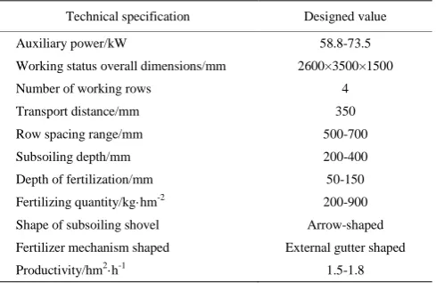
Table 1 Parameters for the machine
Technical specification Designed value
Auxiliary power/kW 58.8-73.5
Working status overall dimensions/mm 2600×3500×1500
Number of working rows 4
Transport distance/mm 350
Row spacing range/mm 500-700
Subsoiling depth/mm 200-400
Depth of fertilization/mm 50-150
Fertilizing quantity/kg·hm-2 200-900 Shape of subsoiling shovel Arrow-shaped Fertilizer mechanism shaped External gutter shaped
Productivity/hm2·h-1 1.5-1.8
2.3 Subsoiling machine set and soil penetrating analysis A subsoiling variable rate fertilization machine consists of a subsoiler handle and a subsoiler tip. The subsoiling device consists of 5 groups of subsoilers, which are installed on the frame in the form of straight lines.
At the start of each soil penetrating operation, a shorter penetrating distance can lead to a higher working performance of the subsoiling machine while the subsoiling shovel satisfies the power allocation by the tractor.
The tractor and the subsoiling machine constitute a suspension subsoiling set via a suspension mechanism. The suspension parameters can be reasonably selected during the operation, ensuring subsoiling quality and shortening the penetrating distance. The suspension parameters of the machine were adjusted through the three-point suspension mechanism. As the machine proceeded, the penetrating angle (γ) caused the subsoiling shovel to penetrate. As the depth rose, γ gradually decreased. The ground wheels controlled the subsoiling depth, and after reaching the pre-set depth,
γ was minimized as shown by γ0 in Figure 2. The size of the
penetrating angle directly affected the depth of soil penetration. The enlargement of γ can shorten the penetrating distance. The theoretical orbit of soil penetration can be approximated as follows[31]:
0
cot 2
S a
(1)
where, a is the tillage depth, cm; S is the penetrating distance, cm; γ
is the initial penetrating angle, (°); γ0 is the penetrating angle at
pre-set depth, (°).
When the dimensions of the suspension mechanism were fixed, the size of γ was related to the position of the instantaneous center, as γ decreased with the forward lead of the instantaneous center and vice versa. Figure 2 shows the penetrating angle of the subsoiling shovel corresponding to different tie bar lengths. The appropriate penetrating angle can be adjusted by changing the tie bar length (AB) of the tractor.
The soil penetrating angle of the subsoiling shovel is usually 8°-30°, and the penetrating angle between the new machine and the shovel shaft perpendicular to the ground is 18°, and thus, the penetrating angle can be set to 0°-12°. At a certain tillage depth, an extremely large penetrating angle will accelerate the augmentation of resistance. Thus, the penetrating angle should not be extremely large or small.
The height of the tractor’s upper and lower suspension points was 82 cm and 47 cm respectively, and the distance from the lower suspension point to the subsoiling shovel support surface was 48 cm. The length of the regulation suspension shaft was 65 cm, the distance from the upper suspension point to the subsoiling shovel supporting surface was 105 cm, and the initial penetrating at this moment angle was 7.5°. According to Equation (1), the
penetrating angle at the pre-set depth of 31.3 cm was determined by the trajectory method to be 3°. Based on Equation (1), the penetrating distance was 169 cm. At this moment, the subsoiling depth and the penetrating distance both satisfy the requirements of Conservation Tillage Equipment-Subsoilers (GB/T24675.2-2009).
3
Control and realization of variable rate fertilization
3.1 Variable rate fertilization controller
A variable rate fertilization control system based on the processor of a PCM-9363 industrial control mainboard (Advantech) was established. This mainboard has an Intel Atom N455 1.66G processor with 6 USB2.0 interfaces, 3 COM ports, 1 CF card slot, 2 1000M LAN interfaces and 2 SATA interfaces. The block diagram of the control system is shown in Figure 3.
Figure 3 Variable rate fertilization control system block diagram
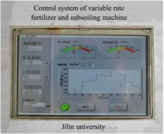
Through the man-machine interaction mode, the microprocessor reads in operational order and displays the operational data. According to the operational position of the machine, the microprocessor transfers the fertilization decision data and controls the motor driver to adjust the motor speed after calculation.
Figure 4 Variable rate fertilization controlling interface 3.2 Fertilizing quantity and penetrating distance matching model
During the routine operation of variable rate fertilization, the fertilizing quantity corresponds one-by-one to the position of the machine. At the progressive penetrating stage, the machine is consistent with the fertilizing quantity after the penetrating distance is reached. The designed penetrating distance of the machine is 169 cm, and at this stage, the subsoiling of the machine is deepened gradually along with the subsoiling distance and the depth of fertilization is increased. As for conventional variable rate fertilization, the soil penetration at the initial stage is equal to the fertilizer quantity at the later stage of soil penetration. At this moment, the depth of fertilization is shallow, but the fertilizing quantity is large and the fertilizers are easily volatile, causing the waste of fertilizers.
A progressive variable rate fertilization method was studied for matching the penetrating distance to avoid the above problems.
Consequently, as the penetrating distance increased gradually and after the entire penetrating distance was covered, the fertilizing quantity reached the normal level of fertilization quantity in the corresponding grid.
The motor speed, grid fertilizing quantity, driving speed, and penetrating distance satisfy the following relationships:
1
s
n n
S
(2)
3
10 10 6
q vBQ (3)
qknb (4)
3
1 10
( 10 )
6
n vbQ b
k
(5)
where, n1is rotating speed at a certain time, r/min; n is the normal
rotating speed of the corresponding grid, r/min; S is penetrating distance (which was 1.69 m in this study); s is finished distance, m;
k is coefficient constant; b is coefficient constant; v is driving speed of the machine, km/h; B is the distance between fertilizer tubes, m;
Q is fertilizing quantity of a certain grid, kg/hm2; q is fertilizing quantity per unit time of the fertilizer device, kg/min.
The above equations indicate that:
3 1
s 1 10
( 10 )
6
n vbQ b
S k
(6)
The relationship between the fertilizing quantity and the penetrating distance can be expressed as Equation (6). As the penetrating distance increases gradually, the control system also adjusts the rotating speed of the motors gradually and avoids the unreasonable use of fertilizers, thereby increasing the fertilizer utilization rate at the initial soil penetrating stage of the fertilizer machine.
3.3 Positioning method of variable rate fertilization
operation with the single-chip microcomputer, and realizes the variable fertilization by adjusting the speed of the motor.
The system has two ways of positioning: a differential global positioning system (DGPS) and straight-line path positioning based on the planar coordinate system.
In DGPS, the system receives DGPS signals and together with latitude and longitude grids of the operational plot drawn in advance, acquires the current spatial position of the machine, determines the fertilizing quantity and controls the action of the variable rate fertilization machine, thereby realizing variable rate fertilization. It is necessary to set the grid row and row number of straight-line path positioning based on the plane coordinate system to obtain the fertilization strategy of the spatial position and realize the variable fertilization.
If the system is not equipped with DGPS or the DGPS signals cannot be read normally due to failure, then the operating positions of the machine and devices can be acquired by using the positioning system based on the planar straight-line coordinate system. The working process is as follows. Any edge on the working plot is selected as the starting boundary line and origin O
is viewed as the starting point (Figure 5a). The starting boundary line is treated as the y-axis of the 2D planar coordinate
system, and the line passing O and perpendicular to the y-axis is the x-axis. The working grids are divided according to the requirements (Figure 5b) and the numbers of rows and columns are pre-set. The grid dimension was set to 20 m×20 m. The column numbers in parallel to the y-axis are marked as A, B, C,···; the row numbers in parallel to the x-axis are labeled according to the position of O as 1, 2, 3,··· and –1, –2, –3,···, all grids were marked. For any incomplete grid in a smaller area than one grid, the fertilizing quantity was the same as that of the longitudinal neighbouring grid (for instance, the fertilizing quantity of A5 was set according to that of A4). After starting the machine, the horizontal and longitudinal distances from O were calculated, thereby obtaining the row and column numbers of the corresponding grid. Thus, the fertilization strategy at the corresponding position that controlled the action of the variable rate fertilization executive mechanism and realized the variable rate fertilization was determined. Prescriptions chart by measuring soil, timely grasp the state of soil fertilizer, and the variable-rate fertilization was realized. When a certain area of machinery operation, timely correction and determine the position of the machine to ensure accurate fertilization. The positioning process is illustrated in Figure 5.
a. Definition of starting point b. Grid division c. Numbering of grids
Figure 5 Variable rate fertilization positioning method
4 Field tests
4.1 Test conditions
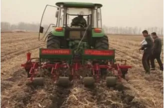
The operational performance of the subsoiling variable rate fertilization machine was tested in the experimental fields of Jilin Agricultural University. The factors tested included subsoiling stability, soil bulkiness, soil disturbance coefficient, machine sliding rate, soil breaking rate, water content and variable rate fertilization performance. The quality of the subsoiling operation was determined as per GB/T 24675.2-2009. The tested plot was a 260 m×180 m rectangle covering an area of 46 800 m2. The tested plot featured flat terrains and black loam soils and was covered with minor straws. The concrete parameters of the field tests are listed in Table 2.
Table 2 Parameters for the field
Item Parameter
Soil type Black loam soil
Full-thickness mean value of soil cone index/kPa 734 Full-thickness mean value of soil moisture content/% 12.9
Ridge top width/mm 222
Ridge distance/mm 650
Ridge height/mm 84
Vegetation coverage/kg·m-2 0.22
Stubble height/mm 100
Soil hardness/kPa 734
Figure 6 Experiment in field of subsoiling and variable rate fertilization machine
4.2 Subsoiling experiment
The experiments were conducted at the speed of 3 km/h or 5 km/h, calculate the relevant data according to Equations (7)-(10), and each approaching speed was considered as one working condition. Each working condition was tested with two strokes. The concrete data are listed in Table 3.
j
j
n
ji n j
j
a a
n
(7)
2 1
( )
1 j
n
ji j
i j
j
a a
s
n
100%
j j
j
s V
a
(9)
Uj=1–Vj (10)
where, aj is the average depth of j distance, cm; ajiis the depth of i
point in the j distance, cm; nj is determination points in the j
distance; sj is the depth of subsoiling standard deviation for j
distance, cm; Vj is coefficient of variation of depth of subsoiling in
the j distance, %; Uj is stability coefficient of the depth of
subsoiling in the j distance, %.
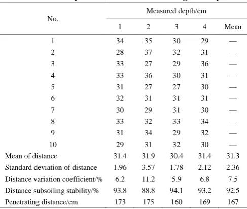
Table 3 Experimental data of subsoiling stability
No.
Measured depth/cm
1 2 3 4 Mean
1 34 35 30 29 —
2 28 37 32 31 —
3 33 27 29 36 —
4 33 36 30 31 —
5 31 27 27 30 —
6 32 31 31 31 —
7 30 29 31 30 —
8 33 32 33 34 —
9 31 34 29 32 —
10 29 31 32 30 —
Mean of distance 31.4 31.9 30.4 31.4 31.3 Standard deviation of distance 1.96 3.57 1.78 2.12 2.36 Distance variation coefficient/% 6.2 11.2 5.9 6.8 7.5 Distance subsoiling stability/% 93.8 88.8 94.1 93.2 92.5 Penetrating distance/cm 173 175 160 169 167 The subsoiling variable rate fertilization machine performed stably during the operations. The average subsoiling depth from the four distances was 31.3 cm, with a mean variation coefficient of 7.5% and a subsoiling stability of 92.5% (Table 3), which all met the requirements of subsoiling depth.
The operational performance of the second distance was worse than that of the other distances. The variation coefficient and subsoiling stability were 11.2% and 88.8%, respectively. These results can be attributed to the abundant amount of stubbles left in the second distance that led to the much soil being carried out during subsoiling. Consequently, the measured values of subsoiling depth were largely different from those in other positions. 4.3 Positioning accuracy testing
The straight-line route positioning algorithm based on the planar coordinate system was tested to validate the precision of the positioning algorithm. At the stable working stage of the machine, the grid numbering was changed when a certain grid drove to the next grid. At this moment, the vertical distance of the fertilizer opener away from the grid boundary line was defined as the absolute error of the positioning algorithm. The positioning error was determined as follows:
100%
L
(11)
where, Δ is the absolute error of positioning, m; L is grid edge
length (here L = 40 m).
The testing data are listed in Table 4.
Table 4 Experimental data of positioning
No. Absolute error of positioning/m
Relative error of positioning/%
1 0.12 0.29
2 0.49 1.22
3 0.06 0.14
4 0.91 2.27
5 1.07 2.68
6 0.60 1.49
7 0.24 0.59
8 0.84 2.09
9 1.19 2.98
10 0.88 2.19
Maximum error 1.07 2.68
Minimum error 0.06 0.14
Mean error 0.64 1.59
During the positioning accuracy testing, ten grids were selected and tested separately. Results showed that the maximum absolute error was 1.07 m with a mean absolute error of 0.64 m and the maximum relative error was 2.68% with a mean relative error of 1.59%. The positioning precision can meet the performance requirement.
4.4 Variable rate fertilization tests
During the variable rate fertilization tests, calculate the relevant data according to Equations (12)-(15), the five theoretical fertilizer quantities were tested separately, and each zone was tested four times. At each time, the fertilizers discharged from each outlet were collected and the single-row and overall delivery consistencies were tested. The testing data are listed in Table 5.
1
'
'
'
'
2
n
x
x
S
i (12)'
'
'
x
S
V
(13)
1
'
2
n
x
x
S
i (14)x
S
V
(15)where, S′ is the standard deviation of single-row delivery
consistency, kg; V′ is variation coefficient of single-row delivery
consistency, %; S is standard deviation of overall delivery
consistency, kg; V is variation coefficient of overall delivery consistency, %; xi′is total delivery per row of each time, kg; xi is
average delivery per row of each time, kg; x is average delivery per row, kg; x is total average delivery of each time, kg.
Table 5 Experimental data of consistency for fertilizer
Item 1 2 3 4 5 Mean
Standard deviation of single-row delivery consistency 0.0424 0.0681 0.0683 0.102 0.137 0.08356 Variation coefficient of single-row delivery consistency 7.10% 7.50% 5.80% 6.80% 7.80% 7.00% Standard deviation of overall delivery consistency 0.0383 0.0777 0.0695 0.169 0.0942 0.08974 Variation coefficient of overall delivery consistency 1.60% 2.10% 1.50% 2.80% 1.30% 1.86%
Real fertilizer delivery/kg·hm-2 336.4 510.2 660.2 841 985.4 ——
Theoretical fertilizer delivery/kg·hm-2 350 520 680 860 1000 ——
During the variable rate fertilization tests, the variation coefficient of the single-row delivery consistency was maximized at 7.80% and the variation coefficient of the overall delivery consistency was maximized at 2.80%. The error of fertilizer delivery was maximized at 3.89% with a mean error of 2.47% and the error of fertilizer delivery declined with the increase of the fertilizer delivery quantity. These results can be attributed to the granular compounds used as fertilizers in the tests. The filling degree of the fertilizer device’s external sheave affected the quantity of fertilizer delivery. Furthermore, when the quantity of fertilizer delivery was small (the quantity of fertilizer delivery was proportional to the rotating speed of the fertilizer device), the errors caused by the filling degree increased. Hence, as the quantity of fertilizer delivery increased, the errors of fertilizer delivery declined gradually and the consistency of the overall delivery became higher than that of the single-row delivery.
5 Conclusions
A subsoiling variable rate fertilization machine for conservation tillage in the black soil regions of Northeast China was designed. The machine consists of frames, a variable rate fertilization device, a subsoiling device, a compacting device, a ridging device, a profiling mechanism, a marking gauge, and supporting ground wheels. The tested indices meet the national and industrial standards and satisfy the design requirements.
The relationship between the suspension parameters and the penetrating distance was analyzed, and a matching model between fertilizing quantity and penetrating distance was established and used to adjust and control the fertilizing quantity at the penetrating distance stage. The straight-line path positioning algorithm based on the planar coordinate system was investigated and used in the variable rate fertilization control system.
The subsoiling variable rate fertilization machine was tested to validate its operational performance. The machine integrates variable rate fertilization and subsoiling and features a subsoiling stability of 92.5%, a soil breaking rate of 61.1%, a maximum relative error of positioning of 2.68% and a maximum error of variable rate fertilization of 3.89%, all which satisfy the requirements of subsoiling and variable rate fertilization. This machine underlies experimentally the integrated application of subsoiling and variable rate fertilization.
Acknowledgements
The authors acknowledge that this work was financially supported by the National Natural Science Foundation of China (No. 31401284) and the National Key Technology Research and Development Program of the Ministry of Science and Technology of China (No. 2014BAD06B03).
[References]
[1] He J, Li H W, Chen H T, Lu C Y, Wang Q J. Research progress of conservation tillage technology and machine. Transactions of the CSAM, 2018; 49(5): 1–19. (in Chinese)
[2] Liu C L, Yuan J, Liu J Z, Li C X, Zhou Z L, Gu Y X. ARM and DSP-based bivariable fertilizing control system design and implementation. Transactions of the CSAM, 2010; 41(Supp1): 233–238. (in Chinese) [3] Tang H, Wang J W, Xu C S, Zhou W Q, Wang J F, Wang X. Research
progress analysis on key technology of chemical fertilizer reduction and efficiency increase. Transactions of the CSAM, 2019; 50(4): 1–19. (in Chinese)
[4] Lang C L, Wang J W, Wang J F, He J N, Xi X H. Variable fertilizer control system for deep-fertilization liquid fertilizer applicator.
Transactions of the CSAM, 2013; 44(2): 43–47, 62. (in Chinese)
[5] Yu H F, Ding Y Q, Liu H T, Zhu W Q, Liu G Q, Fu X Q, et al. Optimization design and application of variable rate fertilization system for small-scaled fields. Transactions of CSAE, 2018; 34(3): 35–41. (in Chinese)
[6] Yuan Y W, Zhang X C, Wu C C, Zhang J Y, Zhou L M. Precision control system of no-till corn planter. Transactions of the CSAE, 2011; 27(8): 222–226. (in Chinese)
[7] Zhao Y, Chen X G, Zheng X, Song Q W, Tang Z H, Ren Z Q, et al. Research on accuracy layered fertilization technology. Oasis Agriculture Science and Engineering, 2016; 2(3): 25–29. ( in Chinese)
[8] Chen S F, Zhang S P, Sun X Z, Li Y M. Design and experiment of self-propelled high-ground-clearance spreader for paddy variable-rate fertilization. Transactions of the CSAE, 2012; 28(11): 16–21. (in Chinese) [9] Zhang R, Wang X, Zhao C J, Bai Y L, Meng Z J, Chen L P. Design and
experiment of variable rate fertilizer spreader with conveyor chain. Transactions of the CSAE, 2012; 28(6): 20–25. (in Chinese)
[10] Qi J T, Zhang S H, Yu Y J, Xu Y. Development of a ground speed collecting system for the variable rate fertilizer machine based on Bluetooth. Transactions of the CSAM, 2009; 40(12): 200–204. (in Chinese)
[11] Chattha H S, Zaman Q U, Chang Y K, Read S, Schumann A W, Brewster G R, et al. Variable rate spreader for real-time spot-application of granular fertilizer in wild blueberry. Computers and Electronics in Agriculture, 2014; 100: 70–78.
[12] Grandy A S, Salam D S, Wickings K, McDaniel M D, Culman S W, Snapp S S. Soil respiration and litter decomposition responses to nitrogen fertilization rate in no-till corn systems. Agriculture, Ecosystems & Environment, 2013; 179: 35–40.
[13] Yuan J, Liu C L, Li Y M, Zeng Q B, Zha X F. Gaussian processes based bivariate control parameters optimization of variable-rate granular fertilizer applicator. Computers and Electronics in Agriculture, 2010; 70(1): 33–41.
[14] Meng Z J, Zhao C J, Fu W Q, Ji Y X, Wu G W. Prescription map identification and position lag calibration method for variable rate application of fertilizer. Transactions of the CSAM, 2011; 42(7): 204–209. (in Chinese)
[15] Hu L F, Li H W, Gao H W. Influence of conservation tillage on greenhouse effect. Transactions of the CSAE, 2009; 25(5): 308–312. (in Chinese)
[16] Kassam A, Friedrich T, Derpsch R, Kienzle J. Overview of the worldwide spread of conservation agriculture. Field Actions Science Reports, 2015; 8:1–11.
[17] Qi J T, Jia H L, Li Y, Yu H B, Liu X H, Lan Y B, et al. Design and test of fault monitoring system for corn precision planter. Int J Agric & Biol Eng, 2015; 8(6): 13–19.
[18] Cai G H, He J, Li H W, Wang Q J, Li H, Lu C Y. Comparative analysis of three ridge-loosing cutters based on permanent raised bed conservation tillage. Transactions of the CSAM, 2010; 41(12): 22–28. (in Chinese) [19] Wang Q J, Bai Y H, Gao H W, He J, Chen H, Chesney R C, et al. Soil
chemical properties and microbial biomass after 16 years of no-tillage farming on the Loess Plateau China. Geoderma, 2008; 144: 502–508. [20] Wang G, Jia H L, Tang L, Zhuang J, Jiang X M, Guo M Z. Design of
variable screw pitch rib snapping roller and residue cutter for corn harvesters. Int J Agric & Biol Eng, 2016; 9(1): 27–34.
[21] Feng J K, Cui Y H, Zhen R, Li S K. Review on conservation tillage of double cropping system in North China Plain. Chinese Agricultural Science Bulletin, 2006; 22(6): 177–181. (in Chinese)
[22] Wells L G, Stombaugh T S, Shearer S A. Crop yield response to precision deep tillage. Transaction of the ASAE, 2005; 48(3): 895–901. [23] Zhang J C, Yan X L, Xue S P, Zhu R X, Su G Y. Design of no-tillage
maize planter with straw smashing and fertilizing. Transactions of the CSAM, 2012; 43(12): 51–55.
[24] Wang Q J, Liu Z D, He J, Li H W, Li W Y, He J H, et al. Design and experiment of chopping-type maize straw returning machine. Transactions of the CSAE, 2018; 34(2): 10–17. (in Chinese)
[25] Wang Y X, Zhang D X, Yang L, Cui T, Li Y H, Liu Y W. Design and experiment of hydraulically self-excited vibration subsoiler. Transactions of the CSAE, 2018; 34(11): 40–48. (in Chinese)
[26] Sun Y P, Dong X Q, Song J N, Wang J C, Liu C L, Xu G H. Self-balancing performance and simulation analysis of multi-group vibrating sholvels of oscillatory subsoiler. Transactions of the CSAE, 2018; 34(4): 92–99. (in Chinese)
experiment on anti-blocking mechanism for wheat no-till planter. Transactions of the CSAM, 2010; 41(2): 73–77. (in Chinese)
[28] Zheng Z Q, He J, Wang Q J, Li H W, Li W Y, Chen W Z. Design and experiment on straw pickup-chopping and ditch-burying integrated machine. Transactions of the CSAM, 2017; 48(7): 87–96. (in Chinese) [29] Jia H L, Ji W F, Han W F, Tan H J, Liu Z C, Ma C L. Optimization
experiment of structure parameters of rototilling and stubble breaking
universal blade. Transactions of the CSAM, 2009; 40(7): 45–50. (in Chinese)
[30] Qi J T, Jia H L, Zhuang J, Fan X H, Liu C X, Liu D D. Effective clearance calculation of three-point hitch linkage for rototilling-planting machine. Transactions of the CSAM, 2012; 43(Z1): 24–28. (in Chinese) [31] Geng R Y. New agricultural mechanics. National Defence Industry