World Maritime University
The Maritime Commons: Digital Repository of the World
Maritime University
World Maritime University Dissertations Dissertations
1999
The virtual classroom afloat : maritime education
and training in the 21st century : an investigation
into the feasibility and practicability of distance
learning via the satellite communications system
Dennis G. TanWorld Maritime University
Follow this and additional works at:http://commons.wmu.se/all_dissertations Part of theOnline and Distance Education Commons
This Dissertation is brought to you courtesy of Maritime Commons. Open Access items may be downloaded for non-commercial, fair use academic purposes. No items may be hosted on another server or web site without express written permission from the World Maritime University. For more information, please [email protected].
Recommended Citation
Tan, Dennis G., "The virtual classroom afloat : maritime education and training in the 21st century : an investigation into the feasibility and practicability of distance learning via the satellite communications system" (1999).World Maritime University Dissertations. 423.
World Maritime University
Malmö, Sweden
THE VIRTUAL CLASSROOM AFLOAT
- MARITIME EDUCATION AND TRAINING IN
THE 21
STCENTURY: AN INVESTIGATION INTO
THE FEASIBILITY AND PRACTICABILITY OF
DISTANCE LEARNING VIA THE SATELLITE
COMMUNICATIONS SYSTEM
By
DENNIS G. TAN
Republic of the PhilippinesA dissertation submitted to the World Maritime University in partial fulfilment of the requirements for the award of the degree of
MASTER OF SCIENCE
in
MARITIME EDUCATION AND TRAINING (Nautical)
ABSTRACT
This paper is an investigation into the current trends and developments in ship/bridge design and onboard communications systems, computers, Information Technology (IT) and telecommunications, particularly satellite communications. It also examined selected researches/experiences into the onboard learning environment by some companies or organisations. It explored some of the current distance learning methodologies and the associated technologies used in their delivery both ashore and afloat. This was for the purpose of assessing the technical feasibility and financial viability of establishing a Distance Learning Programme for the Filipino seafarers who comprise 20% of the world’s manning supply. The study endeavoured to make a detailed cost estimate of the resources necessary such as financial, material, human and other resources in establishing and running such a programme. A cost-benefit analysis was made between a conventional training programme vis-à-vis one delivered via distance learning. To further determine its viability and practicability, a pioneering survey of the Filipino seafarers was made to gauge their readiness and receptiveness to new approaches to MET, i.e. distance learning. It was also a means to find out if they possess the attributes contributory to their potential success as distance learners.
This new approach to MET is geared towards solving the current dilemma the country is facing now. That is, meeting both the qualitative requirements of IMO/STCW’95 and satisfying the quantitative demands of the shipping industry to avert a potential international manning crisis.
TABLE OF CONTENTS
Declaration ii
Acknowledgements iii
Abstract vii
Table of Contents viii
List of Tables xii List of Figures xiii
List of Abbreviations xiv
1. Introduction 1
1.1 General Introduction 1
1.2 Background of the Study 3
1.3 Importance of the Study 4
1.4 Purpose of the Study 5
1.5 Research Methodology 6
1.6 Scope and Delimitation 8
2. An overview of technology in the maritime environment 9
2.1 Ship design and bridge systems: developments and trends 9
2.1.1 Optimal bridge design - the sietas bridge 10
2.1.2 MV Stuttgart Express model 12
2.1.3 The tanker bridge model 13 2.2 The path towards bridge integration: from INS to IBS 15
2.3 Towards a fully integrated ship: developments and trends 19
2.4 Local Area Network (LAN) onboard 21
2.5 Advances in computers and Information Technology (IT) 23
2.5.3 Imaging technology 28 2.5.4 Networks and connectivity 30
2.5.5 New products - offshoot of networking
and connectivity 33
2.5.6 The trans-oceanic connection 34 2.5.7 Marine applications software 35 2.6 Satellite systems: principle and technology - a descriptive
overview 37
2.6.1 Orbit 37
2.6.2 Multiple access 38
2.6.3 Bandwidth 40
2.6.4 Frequency 41
2.6.5 Modulation 42
2.6.6 Coding 42
2.6.7 Bit rate 43
2.6.8 Conclusion 43
2.7 Birds in flight – Commercial communications satellites
in orbit 44
2.7.1 The big birds - Major players in the satellite
industry 44
2.7.2 Other birds over the horizon 50
3 Distance learning methodologies 53
4 Research into the onboard training environment
utilising existing and emerging simulation technology 61
Management experience 65 4.3 Advantages of onboard simulation and computer based
training (CBT) 68
4.4 Requirements for an effective shipboard simulator 69
4.5 Virtual Reality (VR) - An emerging reality in simulation
technology 72
5 Setting up distance learning program utilising satcom
technology: resources and costs involved 75
5.1 Definition of requirements 75
5.2 Distance learning network design architecture 80 5.3 Specific hardware and costs involved 85
5.4 Web-based training solution 88
5.5 Marine applications software and videos needed 90
5.6 Additional facilities and costs involved 90
5.7 Types of communications lines and costs involved 92 5.8 Human resources necessary and approximate costs involved 93 5.9 Functions, activities involved and the organisational
framework required 94 5.10 Summary of cost estimate in setting up a distance learning
programme 96
6 STCW’95 and the Philippines: challenges and opportunities
for new technology, methods and approaches 99
6.1 Impact of STCW’95 on the Philippine MET system 99 6.2 Presentation, analysis and interpretation of data from the NMP
6.3 Technical feasibility and capability 109
6.4 Financial viability and sustainability 113
6.4.1 Cost cutting measures to ensure affordability 118
6.4.2 Revenue-generating measures to help finance training cost 122
6.5 Comparative analysis of conventional course vis-à-vis distance learning 124
6.6 Pros and cons of high-tech distance learning utilising satcom and other technologies in developing countries 129
6.6.1 The pros and concomitant advantages 129
6.6.2 The cons and accompanying disadvantages 131
7 Summary, conclusion and recommendations 134
7.1 Summary 134
7.2 Conclusion 138
7.3 Recommendations 139
Bibliography 144
Appendices 155
Appendix 1 Example Layout of Ship Operation Centre Similar to Nedlloyd’s 156
Appendix 2 Basic Layout of Ship Operation Centre 157
Appendix 3 Questionnaire 158
Appendix 4 Site Map of the Philippines 161
Appendix 5 Seagull’s Onboard Library 162
Appendix 6 Videotel Safety Library 163
Appendix 7 Additional Special Library 164
LIST OF TABLES
Table 1 Micro-chip growth 26
Table 2 Telecommunications connection speeds: sample file
transmission rate 27
Table 3 Training matrix 64
Table 4 COMWEB price quotation for a typical multipurpose room 86
Table 5 SmartClass 2000 proposal 87
Table 6 Projected basic ownership cost 88
Table 7 Cost estimate of setting up and implementing distance learning
programme 97
Table 8-a Summary of responses to questionnaire (y/n) 103 Table 8-b Summary of responses to questionnaire (multiple options) 104 Table 9 Financial projections considering dropout rates:
First year of operation 114
Table 10 Financial projections considering dropout rates:
Second year of operation with 500 enrolees and 10 tutors 115
Table 11 Financial projections considering dropout rates:
Third year of operation with 2000 enrolees and 40 tutors 116
Table 12 Financial projections considering dropout rates:
Third year of operation or beyond with 10,000 enrolees
and 200 tutors 117
Table 13 Enrolment increase and corresponding decrease in average
cost per student 118
Table 14 ARPA cost-benefit analysis case 1- with capital outlay and
LIST OF FIGURES
Figure 1 Sietas bridge model 11
Figure 2 Bridge of M/V Stuttgart Express 12
Figure 3 Tanker bridge model 14
Figure 4 INS and Integrated Bridge System (IBS) concept 17
Figure 5 STN Atlas NACOS 65-3 20
Figure 6 HPA output power vs. input power characteristic 40
Figure 7 WMU computer lab 80
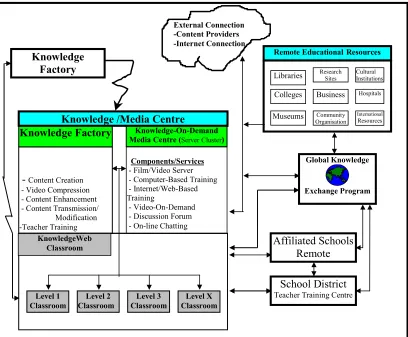
Figure 8 Ed21 - Knowledge Web School 82
Figure 9 Proposed NMP multipurpose and multifunctional 21st century classroom 83
Figure 10 International Datacasting 84
LIST OF ABBREVIATIONS
ABS American Bureau of Shipping
AI Artificial Intelligence
API Applications Programming Interface
ARIES ATM Research and Industrial Enterprise Study
ARPA Automatic Radar Plotting Aid
ARPA Advanced Research Projects Agency
ATM Asynchronous Transfer Mode
BPS Bits Per Second
BPSK Binary Phase Shift Keying
CAD Computer Aided Design
CAL Computer Aided Learning
CALL Computer Aided Language Learning
CBT Computer Based Training
CD-I Interactive CD
CES Coast Earth Station
CHED Commission on Higher Education
CMC Common Messaging Call
CMC Computer Mediated Communication
COLREG Collision Regulation
COW Crude Oil Washing
CPU Central Processing Unit
DAMA Demand Assigned Multiple Access
DGON Deutsche Gesellshaft fur Ortung und Navigation
D.L. Distance Learning
DOLE Department of Labour and Employment
DPI Dot Per Inch
ECDIS Electronic Chart Display and Information System
EIRP Equivalent Isotropic Radiated Power
EMET Enhancing Maritime Education and Training
FDMA Frequency Division Multiple Access
FSS Fixed Satellite Services
GEO Geo-stationary Earth Orbit
GMDSS Global Maritime Distress and Safety System
GPS Global Positioning System
HDTV High Definition Television
HEO High Earth Orbit
HSD High Speed Data
IBS Integrated Bridge System
ICO Intermediate Circular Orbit
IGS Inert Gas System
INMARSAT International Maritime Satellite Organisation
INS Integrated Navigation System
IP Internet Protocol
ISDN Integrated Switched Digital Network
ISM International Ship Management Code
ISP Internet Service Provider
Kbps Kilobit per second
LAN Local Area Network
LCD Liquid Crystal Display
LEO Low Earth Orbit
LES Land Earth Station
MARAD Maritime Administration
MARINA Maritime Industry Authority
MARS /VRS Maritime Surface/Subsurface Virtual Reality Simulator System
MEO Medium Earth Orbit
MNC Multinational Corporation
MTC Maritime Training Council
NACOS Navigation Control System
NMD Norwegian Maritime Directorate
NMP National Maritime Polytechnic
OOW Officer-of-the-Watch
OOWA Overseas Workers Welfare Administration
PC Personal Computer
PRC Professional Regulation Commission
PRN Pseudo Random Noise Code
PSDN Packet Switched Data Network
PSK Phase Shift Keying
QPSK Quaternary Phase Shift Keying
ROM Read Only Memory
Satcom Satellite Communication
SCC Ship Control Centre
SDK Software Developers Kit
SES Ship Earth Station
SHOPSY Ship Operation System
SIA Satellite Industry Association
STCW Standards of Training Certification and Watchkeeping
TC Technical Co-operation
TCP Transmission Control Protocol
3-D Three Dimension
TDMA Time Division Multiple Access
TFT Thin Film Transistor
TNA Training Needs Analysis
UTP Unshielded Twisted Pair
Chapter 1
Introduction
1.1General Introduction
In 1895 Guglielmo Marconi launched a communications revolution in the field of wireless communication that continues to this day. This was widely embraced by the global maritime community, particularly the seafarers, which was rendered incommunicado by virtue of the tyranny of distance and technological limitations onboard at that time.
The development and growth of wireless communications eventually paved the way for mobile communications. Man, being both mobile and a communicator, is attuned to this form of communications, more than any other technique as it imitates the way people communicate naturally.
Onboard computing systems are no longer limited to stand-alone engineering and navigational applications. The growing number of ships with Local Area Network (LAN) onboard reflects the widely recognised need for vessels to become integral parts of shipping companies’ computing and communications networks. This has resulted in ships being transformed into ‘virtual’ floating branch offices. As shore-based businesses depend upon the smooth flow of data through their head offices to branch office computer networks, so now do ships.
For ships at sea, the obvious way to bridge the gap is via satellite communications. The explosive development of sophisticated satellite technology was heralded by the launching of Sputnik 1 on the 4th of October 1957. It was stimulated by the desire to reach and exploit ‘space’. The impact of that technology now touches people’s individual daily lives at every turn, whether it be communications, computers, or even education (Sweeting, 1991). In tandem with the global computer revolution and Information Technology (IT), it is transforming the concept of conventional/ traditional education in general, and maritime education in particular, in quite dramatic ways.
Now satellites are increasingly becoming the fundamental resource for worldwide communications and business transactions as well as in education, albeit to a lesser degree. These ‘extra terrestrial relays’ are providing global links for making people and industries more efficient, more informed, and more secure.
Satellites, more than any other telecommunications technology, are capable of providing ubiquitous coverage anywhere on earth. The satellite industry has been heralded as the undeniable success story of the Space Age.
almost any information onboard. This sets new and exciting opportunities and trends for onboard learning.
This paper endeavours to explore the breadth and depth of the technological impact on the maritime environment in general and maritime education and training in particular.
1.2 Background of the Study
The Philippines has a long and proud tradition of being a maritime nation, spanning centuries from the floating ‘barangays’ of pre-Hispanic times through the historic galleons which traversed the Manila-Acapulco route.
It is an archipelagic country of 7,100 islands. If the 200-mile Exclusive Economic Zone is to be included, stipulated by the UN Convention on the Law of the Sea, the Philippines will have a maritime area of some 57,800 square nautical miles.
Manila is dubbed as the ‘manning capital of the world’. This is because the Philippines is the main source of maritime manpower for the world fleet. In fact, it is often said that one out of every five seafarers is a Filipino. As of 1994, a total of 154,376 Filipino seamen were deployed on board foreign ships. By 1997 the number of registered Filipino seafarers had grown to 437,880 (IMO, TC 47/12/1). It is roughly estimated that some 300,000 of them are active. Together, these seafarers brought in US $2.940 billion in 1994 alone! Thus, there is no telling as to the enormity of its economic contribution to the country.
requirements and finally make it to IMO’s White List, a number of maritime schools and training centres had been closed. Out of the 150 or so schools offering maritime courses only a handful survived. There are only nine schools and training centres that are accredited at the moment, though this is expected to increase up to a dozen later. Paradoxically however, due to the drastic changes and draconian measures taken by the Philippine MET authorities, its primacy as a maritime manpower is threatened. Losing that status and failing to make it to the White List would have grave economic repercussions. It could also trigger a global manning crisis in the shipping community. With only nine (maybe a dozen later) maritime schools meeting the standards, how can the Philippines meet the manpower demands of the industry? Is it a question then of quantity versus quality? The emphasis now on competency-based training further aggravates the problem as it implies fewer students per class. With certificates of competency to be revalidated/renewed every five years, the necessity of taking up refresher program and the Commission on Higher Education (CHED) and Professional Regulation Commission’s (PRC) Continuing Professional Education (CPE) requirements, how will the country’s MET respond? Is there a way to meet the quantitative requirements of the industry without compromising the qualitative demands of international regulatory bodies such as the IMO?
1.3 Importance of the Study
Noting the fact that the Philippines does not have any form of distance learning programme in its maritime education and training system, this study is of particular significance to the country. The findings of this study will enable the country’s MET to evaluate and assess the viability and practicability of establishing a first-of-its-kind distance learning programme using cutting-edge educational technology. It may also be of benefit to institutions in other developing countries that wish to establish a similar programme. Once successfully implemented, this D.L. programme for seafarers at sea utilising computers, IT and satellite communications system could serve as a model for them to follow.
1.4 Purpose of the Study
This research/study has the following specific objectives: 1. To examine the current developments and trends in:
a) modern ships’ design and shipboard communications facilities b) computers and information technology (IT)
c) satellite communications and data transfer
2. To investigate the various distance learning methods being used presently which utilise modern technology.
3. To examine the current trends in management/administrative practices in MET and other institutions employing distance learning.
5. To determine the approximate cost involved in establishing and operating/running such a programme.
6. To review, analyse and evaluate the significance and implications of the findings of selected researches, etc. made regarding onboard learning.
7. To evaluate the pros and cons of D.L. via satcom and its viability and practicability in the developing countries.
8. To make proposals and recommendations for new approaches to MET in the Philippines by harnessing the potential of state-of-the-art technologies.
1.5 Research Methodology
Communication with various maritime related companies or organisations dealing with technologies utilised in distance education such as INMARSAT, MARINTEK, Seagull, FUMAR, COMWEB, Satpool, Consafe, etc. were also made in the hope that their technical expertise could shed light on the investigations made by the author.
The author also made an informal interview with his course professor, some visiting professors to WMU of various nationalities and other experts to elucidate on certain matters he wished to be clarified.
In addition, the author also browsed the Internet and the World Wide Web and visited a number of web sites for information he could not readily find elsewhere. E-mail was often resorted to in contacting organisations/companies/institutions, etc. possessing the knowledge, information or expertise relative to his research.
The last, but not the least, the author, with the help of his institution, the National Maritime Polytechnic, conducted a pioneering survey for the Filipino seafarers, most of whom were officers in which a number of them were occupying senior/ management level positions. There were 574 respondents. The sampling could be considered purposive as it has chosen only Filipino seafarers who are mainly officers. On the other hand, it was also random sampling as the questionnaires were administered to any seafarer they encounter in Manila and in the training site in Tacloban City. To a certain degree, the sampling could be considered accidental as it was administered to the seafarers who happened to be there at NMP’s training complex in Tacloban City and its extension office in Manila.
success in distance studies.
1.6 Scope and Delimitation
This paper focuses only on the existing technologies currently available onboard particularly in the field of computers, Information Technology and telecommunica-tions, including satellite communications. While it covers distance learning methodologies applied onboard as well as ashore, it does not include details in the actual design of distance study materials, though they may be mentioned in passing. It does however introduce and discuss some concepts in the aspect of delivery of distance learning and the associated technologies. Though some technical matters are mentioned, it is not intended to be a technical textbook on satellite communications nor on distance learning. In most cases, it limits its applications mainly to Filipino seafarers and the Philippine maritime environment. It may however also apply to other developing countries under similar circumstances.
The aspect of profitability in establishing the programme is beyond the scope and intent of this study. It does however make sufficient comparison of the costs and benefits between running a conventional simulator course (i.e. ARPA) vis-à-vis one delivered via distance learning.
Chapter 2
An Overview of Technology in the Maritime Environment
2.1 Ship Design and Bridge Systems: Developments and Trends
The genesis of modern ship design was an evolution rather than a revolution or an outright creation. Everard (1997) said that this evolutionary process could sometimes go by for years without major change, then it leaps forward. The main design concept is focused on the bridge and its attendant equipment being the hub of the ship’s navigation, operation and control. For decades innovations in ship design were relatively static. It hardly progressed from the steamboat prototype, except with some occasional step innovations, until recently.
In 1974 the DGON (Deutsche Gesellshaft fur Ortung und Navigation) published a study stating that shipowners, shipyards, and navigators were of differing view as to the operational benefits of the installations in ship bridges of seagoing ships ‘due to the complete lack of applicable standards for the location, the maintenance and the handling and use of the numerous appliances’, (Froese, 1978).
2.1.1 Optimal Bridge Design – The Sietas Bridge
A research proposal for the ‘Optimal Bridge Design on Merchant Vessels’ was presented to the German Minister of Transport in 1971 by the DGON for possible funding. In the design, according to this study, the naval architect should take into consideration the following:
• ergonomic aspects
• separation of the command, navigation and safety workstations
• ease of handling of all equipment at the different workstations from correctly designed chairs
• position appropriate instruments into groups
• instrument standardisation
• ergonomically designed lighting and illumination dials, display coding, interpolation of displayed values, labelling of instruments and control panels, minimum size of legends, size and shape of instruments, shape and colour of knobs, wheels, levers, switches, etc.
In most respects, the design of ship bridges was influenced by the evolution and eventual revolution in computers and information technology (IT). Attesting to this fact was the joint research project of Hamburg University Department of Naval Architecture, the German Shipowners’ Federation and the Fachhochschule Hamburg entitled ‘The Ship’s Bridge as an Information and Decision System’, (Froese, 1978).
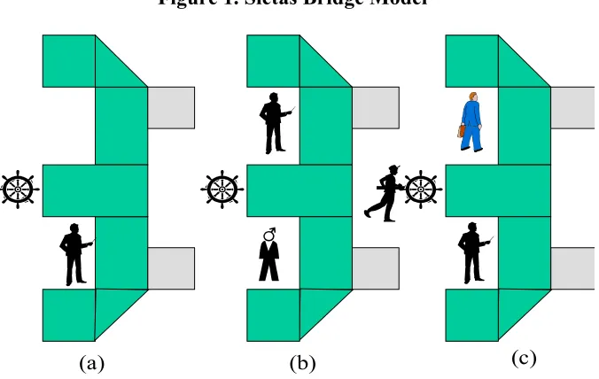
The DGON study produced the Sietas ‘optimal bridges’ where the bridge equipment configuration is typically E-shape, similar to today’s INS and IBS systems, (see Figure 1). The design is claimed to have the following benefits:
• the ship can be manoeuvred safely, particularly during unmanned engine room operation
• the officer on duty is able to manoeuvre the ship from either a sitting or standing position
• the working area is clearly divided into separate command, navigation and radio workstations
• the 360° arc of vision has minimal obstruction
• the basic design is adaptable to ships of different sizes and types of service
There were three basic functional arrangements under the Sietas bridge model designed for a) One-man manning, b) Two-man manning, and c) Three-man manning with the master/OOW, pilot and the helmsman standing at the after end of the middle console, (see Figure 1 a, b, c below).
Figure 1. Sietas Bridge Model
Source: Modified from Froese (1978)
The special requirements of conning faster and bigger container ships brought the necessity for Hapag-Lloyd, the biggest German liner company, to reconsider a new revised bridge design introduced in 1977 on four 33,000 grt. North Atlantic container ships.
2.1.2 MV Stuttgart Express Model
Froese (1978) noted that ‘whereas the Sietas bridge was a yard design, the Hapag-Lloyd’s bridge was developed by the managers and seafaring personnel of a shipping
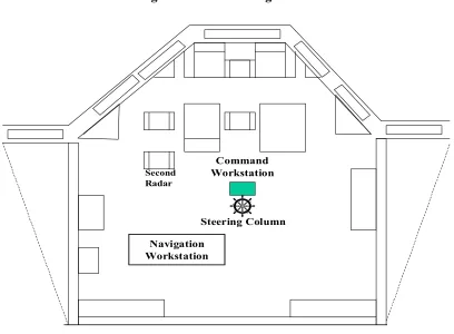
Figure 2. Bridge of M/V Stuttgart Express
Source: Modified from Froese (1978)
Command
Radar and Safety
Cargo Control Navigation
Pilot´s chair
company’. Its basic idea was different and one-man manning was never considered as the aim was greater safety and reduced workload on the navigator.
In this model (see Figure 2 above), typified by the bridge plan of MV Stuttgart Express, the wheelhouse is clearly divided into four workstations: command, navigation, radar and safety and cargo control.
The command console, occupying nearly half of the forward bulkhead, contains all the important controls for the engine, the steering system, external and internal communication, as well as echo sounder and the Doppler log. The chair for the helmsman is adjustable.
For containers, which were the ones considered in the above designs, it was not possible to have a protruding wheelhouse due to loss of container storage space and risk to damage to the bridge during loading and unloading. Tankers do not have this kind of problem and so this design concept was carried out.
2.1.3 The Tanker Bridge Model
As with Sietas bridge design, the so-called ‘Tanker Bridge’ has provision for One Man Manning. In this design, the command workstation consists of a chair installed in the middle of the projecting part of the bridge deck with all the necessary controls readily accessible from this point (see Figure 3).
Ned-Lloyd of the Netherlands has also developed a projecting bridge design for a container ship of over 4,000 TEU. In this case, however, the wheelhouse protrudes on the starboard half thus avoiding obstruction of its forward view as well as minimising wastage of container storage space (see Appendix 1).
Figure 3. Tanker Bridge Model
Froese (1978) was quick to point out that ‘similar bridge designs have been in existence since the early seventies, when the Scandinavians began to take an interest in this aspect of ship design’. No doubt other countries have made their contributions as well.
In another paper, Froese (1991) mentioned the German ‘ship of the future’ research which concluded in 1986 and was succeeded by another research project called ‘ship operation system (SHOPSY)’. Following the client-server concept, it aimed at the development of computer networks and the utilisation of applications running on optional workstations and the decision support systems (DSS).
After a thorough task analysis, implicit in the concept of bridge design is its ability to
Navigation Workstation
Steering Column Command Workstation
Second Radar
design of information displays should be taken into account too, such as the kind of information required, when and where will it be displayed, in what form and how it is perceived by the user/operator. This is something obviously considered in the SHOPSY design.
But today, with the added impetus of technological advances, much of the changes are governed by legislation, says W. D. Everard (1997). Noteworthy also is the significant influence of oil company requirements in the tanker sector.
Further, Everard (1997) noted that ‘the other main “step change” in the design of the bridge evolved from the automation of the engine room’. Vessels built in 1997 have the capability to start/stop the main engine from the bridge as well as paralleling and changing over generators and comprehensively monitoring the alarm and operational status of engine room machinery. Current trends show that with the change in cargo control operations, such as the Saab cargo system, the bridge is fast becoming the focal point of the ship, whether at sea or in port.
Everard (1997) stated that:
Psychologically, the design and layout of the bridge plays an important role in the operation of the vessel and if a considered and practical approach is given to the ergonomics and aesthetics of this workplace the differences in personnel performance can be measurable with both ship’s staff and company enjoying the benefits.
2.2 The Path Towards Bridge Integration: From INS to IBS
navigation, with simple manoeuvring control during the voyage and decreased workload for the navigators, due to an efficient man-machine interface, and with automatically recorded and documented planning and progress reports, (STN Atlas, 1999). With the implementation in July 1, 1998 of the ISM Code and its emphasis on documentation, this automated documentation system is quite a much welcome benefit.
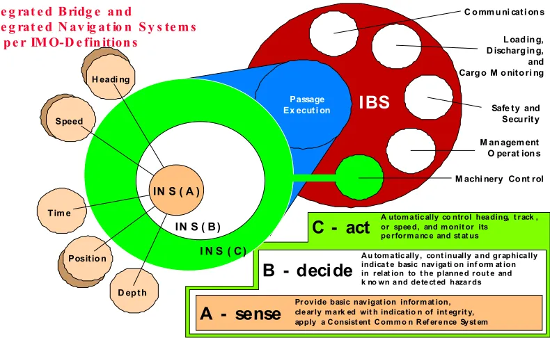
But prior to a full bridge integration, there are three levels of Integrated Navigation Systems (INS) leading ultimately to a fully Integrated Bridge System (IBS) as per IMO definitions. These are:
• INS (A) - This is essentially the sensing category, the lowest level of
integration. It provides basic navigation information such as heading, speed, time, position and depth. Indications of integrity are clearly marked. It applies a Consistent Common Reference System.
• INS (B) - This is the decision category. Referring to Figure 4 it could be
seen that it incorporates all the capabilities of INS (A). But over and above it the system is also capable of automatic, continuous, graphical indication of basic navigational information in relation to the planned route and known and detected hazards.
• INS (C) - Other than incorporating the capabilities of INS-A and B, the
system is also capable controlling the ship. It is the action category.
comprises the controls of the key navigation instruments themselves together with a basic steering stand from which rudder and revs can be adjusted.
• IBS - This is the most comprehensive type of integration. Compuship
quoting IMO’s definition defined it as ‘a combination of systems which are interconnected in order to allow centralised access to sensor information or command/control from workstations, with the aim of increasing safe and efficient ship’s management by suitably qualified personnel’, (Compuship, December 1998/January 1999). It incorporates passage execution, communications, loading/unloading and cargo
Figure 4. INS and Integrated Bridge System (IBS) Concept
Passage Ex ecut i on
C o mm u ni cat i on s
L oad in g, D ischarg in g, and Carg o M o nito ri ng
Safe ty and Securit y
M an agem ent O perat ion s
M achi nery Co nt rol IBS
I N S ( C) IN S ( B) H eadi ng
Speed
Tim e
Positio n
D ep t h
A utom a tic ally co ntrol hea ding, t rack , or spee d, and m onit or its pe rform a nc e and st at us
Pr ov ide basic nav igat ion inform at ion, cle arly m a rk ed wit h indica tio n of int egrit y, apply a C onsist ent C omm o n R ef ere nce Sy st em
A - sense
A u tom a tic ally , cont inually a nd graphica lly indica t e basic nav iga ti on inf orm at ion in relat ion to t he planne d rout e and k no wn a nd de te ct ed haza r ds
B - decide C - act IN S ( A )
In te g rat e d B ridg e an d
In te g rat e d N av ig at io n S y s te m s as p e r IM O-D e fin ition s
monitoring, safety and security, management operations and machinery control.
According to Andy Norris, chairman of the IEC’s technical committee, the body that develops many of the IMO’s functional requirements, ‘Most manufacturers now have packages that are similar in many respects, although they may look different’. Noteworthy also is the fact that the ‘leading manufacturers’ offerings are even superficially similar in appearance: standing-height consoles arranged in a soft “E” shape with the steering stand forming the centre horizontal of the E is a typical arrangement’, (Compuship, December 1998/January 1999). They may differ only in the man/machine interface and some extra features.
With the long-winded genesis of electronic charts now ended (IMO, Nav. 44), several manufacturers have launched new products that raise the level of integration to ever dizzying heights. UK’s Kelvin Hughes is one of them. It has developed a collision avoidance advice system which is part of a ‘near future’ integrated bridge system. ‘It integrates data from the electronic chart display and ARPA to give the mariner detailed advice on what action to take to avoid impending collision situations. If the navigator opts for a certain course of action, the advice system will be able to assess and explain to him what the consequences will be’, said Compuship
(December 1998/January 1999).
manage this information and minimise the risk of ‘information overload’. Norcontrol is trying to grapple with this challenge by introducing its ‘Bridgeline’ IBS. ‘Our philosophy with the integrated bridge’, says its VP for sales and marketing, Leif Pederson, ‘is to give the operator all the information he needs to perform a particular function from any workstation on the bridge - but only the relevant information and nothing more’, Compuship (Decemeber 1998/January 1999).
‘What the leading manufacturers see just over the horizon’, says Compuship
(Decemeber 1998/January 1999), ‘is a time when the availability of so much more data, from many different sources, will bring a demand from shipowners for effective ways to manage and use that information’. The next generation of IBS, according to Norris, will see communications functions integrated within the system and controlled from the different workstations. Compuship (December 1998/January 1999) foresees future systems wherein outgoing as well as incoming data could be sensibly integrated. It said,
Owners will increasingly want operational data sent ashore for analysis. Systems for ballast and bilge control, tank soundings, machinery control, fire detection and alarms, diagnostics, condition monitoring, cargo monitoring, stress measurement and many more all generate data. Integrating them with the navigational information that is traditionally the preserve of the bridge will give superintendents ashore new opportunities for effective fleet monitoring and management.
2.3 Towards A Fully Integrated Ship: Developments and Trends
management, machinery control, alarms, navigation and communication equipment,
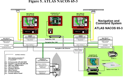
(Compuship, December 1998/January 1999). Its NACOS range of products described as ‘integrated navigation command systems’ and its SCCs (Ship Control Centres) embrace automated communication, engine control and ship management functions. Its top-of-the-line Atlas NACOS 65-3 (see Figure 5) is among the most advanced product in the industry. Referring to Figure 5 makes it obvious that it incorporates a host of functions such as a common workstation technology for Chartpilot, Multipilot and Conningpilot, and central alarm management. It incorporates echo sounder, EM-log, Doppler log, gyrocompass, position sensor, wind sensor, and electronic chart system. The system is even connected to a CD-ROM and a printer, which facilitates documentation and recording of vital information.
1) 1)
Echosounder ATLAS 9205 Doppler Log ATLAS DOLOG EM-Log DEBEG 4675 Gyro Compass Position Sensor Wind Sensor El.Chart System Central Alarm Panel
Navigation and Command System ATLAS NACOS 65-3
A T L A S A T L A S
RADARPILOT Panel
(WITH JOYSTICK)
STN ATLAS ELEKTRONIK
RADAR Panel TRACKPILOT PANEL
WP 1
W P 2
WP 3 WP 1
WP 2
WP 3
MULTIPILOT ATLAS 9106
Ship's Interface connections for up to 10 Navigation Sensors or -subsystems
Radar-Bus, CAN Navigation Bus, CAN
2nd Ship's Interface
Ship's Interface Selector Switch RADAR ELECTRONICS UNIT S-Band Transceiver Electronics
Ship's Interface 2
RADARPILOT Panel
(WITH JOYSTICK)
STN ATLAS ELEKTRONIK
RADAR Panel TRA CKPILOT PANEL
located at chart table
Digitizer Chart Table Printer
CHARTPILOT ATLAS 9300 DP
W P 1
W P 2
W P 3
Navigation LAN, Ethernet
1) 1) CONNINGPILOT
ATLAS 9301
Depth 123.5 m
0 50 100 150 200
Wind 45 deg 5.1 m/s HEADING SET TRA CK SET RA DIUS
N W E S 0 50 100 150 Depth 119,60 m
MULTIPILOT ELECTRONICS UNIT ARPA Indicator Electronics CD-ROM ECDIS Electronics MULTIPILOT ELECTRONICS UNIT ARPA Indicator Electronics CD-ROM ECDIS Electronics RADAR ELECTRONICS UNIT X-Band Transceiver Electronics
Ship's Interface 1
TRACKPILOT ELECTRONICS UNIT TRACKPILOT Electronics Engine Interface SPEEDPILOT Electronics WP 1 WP 2 WP 3 WP 1 WP 2 WP 3 MULTIPILOT ATLAS 9106
1)
1) 1)
1)
1)
Figure 5. ATLAS NACOS 65-3
The aforementioned advances in ship design and automation, which led ultimately to integration, had been driven by the desire to cut costs by reducing to the lowest safe manning level and the reduction of installation and maintenance costs by simplifying and minimising interconnections, (Sperry Marine Inc./Honeywell Limited, 1995).
2.4 Local Area Network (LAN) Onboard
One key to making bridge integration technology feasible is the availability of powerful, affordable computer hardware. Computers are indispensable in the process of distributing, displaying, correlating and interpreting and logging shipboard data and information. As the number of communicating devices increased, parallel to the information explosion on the bridge, the number of interconnecting wires increased dramatically causing a logistical nightmare and maintenance headache. With the introduction of local area networks (LAN) onboard, these problems brought about by advanced technology have been greatly alleviated. LANs facilitate file transfer and data exchange among the various equipment and components, which make higher levels of bridge automation and integration possible. They are the high-speed communications systems designed to allow many computers to simultaneously communicate with one another. It is the ‘glue’ that binds all these hosts of various component functions.
SeaNET is an application of the IEEE 802.5 Token Ring Network Standard. It gives high-speed data distribution and highly reliable transfer. SeaNET is a central integrating element of integrated bridge systems.
The token ring architecture and SeaNET’s real-time interface provide a distributed network that can guarantee deterministic access to the network for all devices. With it files can be transferred from any network node to any other node at speeds comparable to the speeds that files can be written to a hard disk. Data log files can be moved from the VMS Command Station to the NWS for transfer to removable media such as floppy disk or optical disk (CD) or even to the SATCOM, if fitted, for transmission to home office.
Muirhead (1998) noted that:
The increasing installation of Local Area Networks (LANs) on ships reflects the slow but growing realisation by some ship managers that the linking of the total ship to the company LAN ashore can increase interaction between both and lead to improved efficiency, safety and cost-effectiveness.
In the ship’s case, however, the use of Internet, e-mail and data transfer services will be dependent on the satellite link of the communications network architecture.
2.5 Advances in Computers and Information Technology (IT)
2.5.1 The Evolution of Computer Technology - A Brief History
It has been said that necessity is the mother of all inventions. So likewise the computer was born out of some pressing necessity. In this case it was the census of a growing population in 1890. Herman Hollerith reduced the processing time of census information from over ten years to three years by inventing a machine that stored data printed as holes punched on cards. He then manufactured his invention and later merged with another company, which gave birth to the once monolithic giant in the computer industry, IBM (International Business Machines).
ENIAC was the first general-purpose electronic digital computer. It was introduced in 1945. This mainframe computer, the size of a building, occupied 3000 cubic feet of space, weighed 30 tons and contained 18,000 vacuum tubes. This machine was only capable of doing simple addition, subtraction, multiplication, and division. However, it did the job in a programmed sequence, (Forcier, 1996).
The size of the original computers was significantly reduced with the replacement of vacuum tubes with transistors in 1951. It shrank from the size of a building to the size of a room. Later it reduced further to cabinet size.
1975 onwards with the introduction of the integrated circuit or microchip, brought another further reduction in computer size. Apple and Radio Shack microcomputers were among the foremost exponents of this generation of computers called hobby kits.
also capable of performing more complex tasks. It served as a high-powered calculator, a word processor, a means of generating graphics from tabular information, and much more.
1993 gave birth to Apple’s laptop Mackintosh PowerBook 540. In marked contrast to its massive ancestor, ENIAC, weighing 30 tons and occupying 3000 cubic feet, it weighed only about seven pounds and occupied less than one-seventh cubic foot of space. But amazingly, this diminutive offspring had 3000 times greater memory than its gigantic ancestor (36 MB against a paltry 12K) and is 100,000 times more reliable, (Forcier, 1996).
A few years later, ever smaller and more powerful versions came into being. Notebooks are now superseding laptops. Toshiba even developed a smaller version nearly half the size of notebooks with similar capabilities and aptly called it Libretto.
Today, the market is flooded with even smaller handheld PCs otherwise known as palmtops. Philips’ Velo 500, for instance, weighs less than 500 grams. While it can never replace the desktop PC as some notebooks can, its on-the-move convenience coupled with a low-price affordability makes it a very attractive option. Its ‘75mhz RISC processor and 16MB onboard memory along with Windows CE and bundled “pocket” versions of Microsoft Word, Excel, PowerPoint and other popular productivity and communications applications make the Velo 500 the world’s most powerful handheld PC. With an optional low-power modem it can be used with GSM mobile phone to access e-mail, receive faxes or even surf the web[!]’, (Newsweek, November 30, 1998).
Possession of miniaturised yet sophisticated computers, like the Velo 500, make them fantastically powerful tools in the hands of lecturers on the go.
What is amazing with this notebook computer is its 3-D graphics accelerator. ‘This means you can play Direct 3-D supported games ... in blazing 3-D glory [!]’, (Newsweek, November 30, 1998). What do products of this sort then portend? Well, it is obvious, using it in 3-D simulation akin to virtual reality for marine applications will deliver a powerful wallop in its pedagogical impact.
2.5.2 Advances in Information Technology (IT)
Technology has always been the driving force behind most of any modern day progress. Terpstra, (1991, p. 134) defined technology as ‘a system of ordered information concerning the relationship of humans to the material environment from which they appropriate resources and transform them into socially desirable products.’ Looking back at the trends of human history, one could see how the role of changing technology influenced every trend and shift in human activities. ‘The recent ‘shifts’, Terpstra added, ‘correlate with technological control of data generation and its processing into information.’
This ‘control, generation and processing’ of data is what Information Technology (IT) is all about. IT provides data to aid in decision making. But data has to be transformed into information before it becomes a vital tool in decision making. It is communications that turns business data into information.
‘IT’, says Patrick Slesinger, (1998), ‘is, in most cases, now the only way that companies can compete in this ever faster moving world. No longer can companies afford for IT to be treated as a “back room” activity or for IT strategy not to be a Board level concern’.
standard data protocols to exchange information with one another’. It had its origins in the late 1960s, when the US Department of Defence Advanced Research Projects Agency (ARPA) developed packet switching techniques for transferring data between computers. By 1973 the first rudiments of the Internet, then called ARPAnet, had been created. A major impetus brought about by the introduction of a standard protocol called TCP/IP (Transmission Control Protocol/Internet Protocol) in 1972 caused the rapid expansion of the Internet. But only since 1993 did it begin to
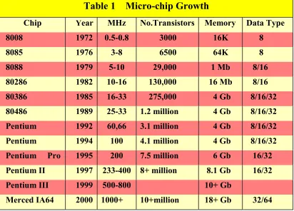
Table 1 Micro-chip Growth
Chip Year MHz No.Transistors Memory Data Type
8008 1972 0.5-0.8 3000 16K 8
8085 1976 3-8 6500 64K 8
8088 1979 5-10 29,000 1 Mb 8/16
80286 1982 10-16 130,000 16 Mb 8/16
80386 1985 16-33 275,000 4 Gb 8/16/32
80486 1989 25-33 1.2 million 4 Gb 8/16/32
Pentium 1992 60,66 3.1 million 4 Gb 8/16/32
Pentium 1994 100 4.1 million 4 Gb 8/16/32
Pentium Pro 1995 200 7.5 million 6 Gb 16/32
Pentium II 1997 233-400 8+ million 8.1 Gb 16/32
Pentium III 1999 500-800 10+ Gb
Merced IA64 2000 1000+ 10+million 18+ Gb 32/64
Source: Muirhead (1998), Methar Project
This number will soar to 304 million [!] by 2002, according to Joan-Carol Brigham, an analyst with Data Corp. The foregoing figures clearly indicate the rapid expansion of the Internet being the fastest growing segment of IT development.
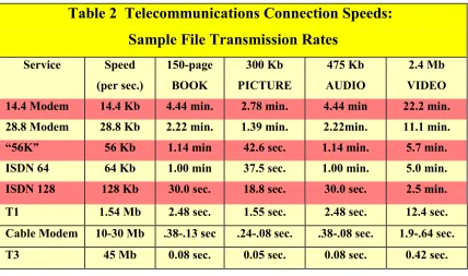
Parallels to these developments are improvements in the processing power of computer technology. ‘At a given price it continued to double approximately every 18 months [i.e. power improvement cost reduction cycle]’, observed Kinnaman and Dyrli (1996). Further they stated that: ‘Computer-based telecommunications are developing at breakneck speeds and new products and services are quickly supplanted by more powerful options’. Current trends show (see Table 1 and 2) that telecommunications speed have increased and will continue to increase dramatically.
Table 2 Telecommunications Connection Speeds:
Sample File Transmission Rates
Service Speed
(per sec.)
150-page BOOK
300 Kb PICTURE
475 Kb AUDIO
2.4 Mb VIDEO
14.4 Modem 14.4 Kb 4.44 min. 2.78 min. 4.44 min 22.2 min.
28.8 Modem 28.8 Kb 2.22 min. 1.39 min. 2.22min. 11.1 min.
“56K” 56 Kb 1.14 min 42.6 sec. 1.14 min. 5.7 min.
ISDN 64 64 Kb 1.00 min 37.5 sec. 1.00 min. 5.0 min.
ISDN 128 128 Kb 30.0 sec. 18.8 sec. 30.0 sec. 2.5 min.
T1 1.54 Mb 2.48 sec. 1.55 sec. 2.48 sec. 12.4 sec.
Cable Modem 10-30 Mb .38-.13 sec .24-.08 sec. .38-.08 sec. 1.9-.64 sec.
T3 45 Mb 0.08 sec. 0.05 sec. 0.08 sec. 0.42 sec.
Source: Odvard Egil Dyrli and Daniel E. Kinnaman, Technology and Learning, April 1996
2.5.3 Imaging Technology
Enhanced image quality will be another benefit of tomorrow’s office-imaging tools. Canon recently demonstrated a new microfine-droplet technology, which promises to bring ultrahigh, photo-realistic images to the colour ink-jet world. ‘Within a year or so, we’ll be producing printers whose output will be virtually indistinguishable from silver halide photographs at least to non professionals’, says Salmon, European market-planning manager for Canon Europa (Newsweek, November 30, 1998).
On the same Newsweek issue Takyoshi Hanagata, group executive of Canon BJ Printer Products Business Group, said, ‘We think bubble jet technology has the potential to rival, and possibly even surpass, colour-print speeds now offered in laser beam printers and midspeed copiers’.
Televisions and computer monitors, on the other hand, made their own technological quantum leaps in recent years too. From pure black and white display, to bright trinitron CRTs were later developed. Shortly afterwards, Sony’s black trinitron was introduced to improve contrast as well as brilliance. Other manufacturers made their own innovations too along the same lines.
Computer monitors also made parallel progress from monochrome to colour VGA and now to super VGA.
For television, the screen size also grew bigger from 27 inches in the early 80’s to 45 inches and even bigger to the incredibly immense size of screen measured in feet or metres today.
higher DPI and, naturally, many times clearer and 2.5 times brighter than standard TV. Pictures on this screen really come alive. They seem to ooze out of the screen so wondrously colourful and vibrantly teeming with life. You could almost touch them. However the first versions were based on old analogue technology and digital versions were later developed with further refinements. Today, delicate surgical operations via telemedicine are performed utilising these technological wonders in imaging. The advent of digital TV and Web TV allowing one to surf the Net, caused a blurring in the demarcation of what is TV and what is computer. The beauty of this technology is that it allows for the possibility of manipulating video pictures for better visual effects, which has enormous potential for pedagogical applications.
But imaging technology did not stop here. Liquid Crystal Display (LCD) screens were developed a decade or so earlier. Their viewing angle and clarity however were limited. But more and more innovations were made to refine and improve it. Today, a new generation of lightweight, flat panel LCD monitors may soon ‘replace the bulky CRT in offices and homes around the world’, predicts Hugh Brogan (Newsweek, November 30, 1998), general manager of Taiwan-based Philips PC Peripheral Division. Philip’s new Brilliance TF15AX 15-inch monitor, for instance, is less than 18 cm deep and weighs only 5.2 Kg., a fraction of the size of a conventional 38 cm monitor. Thin-Film-Transistor, or TFT, technology made it possible. Since each picture-producing element has its own transistor, TFT-LCD flat screen monitors produce the brightest colours, the highest contrast and the fastest response time of any monitor on the market today, says Brogan (Newsweek, November 30, 1998). These TFT screens allow for wide viewing angle unlike conventional LCDs.
offer the potential for extremely large formats. These displays have extremely wide-viewing angle of 160 degrees or more with virtually no picture distortion. They are also super lightweight and therefore ideal for unfettered deployment on office, and who knows, classroom, walls too!
Imagine the thrill of having a videoconference in a grandiose boardroom or a large auditorium utilising this imaging technology. What impact would it have on a student running a ship manoeuvring simulation displayed on a life-size wall-mounted screen right in his/her bedroom?! By any stretch of the imagination the future is replete with stupendous potential.
2.5.4 Networks and Connectivity
Initially computers, PC or otherwise, were stand-alone equipment. As their computing power and sophistication increased and their memory capacity expanded dramatically, coupled with the realisation of the synergetic advantages of connectivity, linkage with other computers did not only become possible but ultimately inevitable. These linkages and interconnectivity in the form of a network system linking several PC’s to a file server provided extra flexibility and power. Networking started as local area network (LAN) composed of devices housed in close proximity to one another and growing into a wide area network or WAN, a network that spans great distances or covers a wide geographical area, (Forcier, 1996). Ultimately it reached the pinnacle in what is now a by-word, the Internet, the mother of all networks.
institutions] to link their intranets behind the protection of virtual firewalls and other security features’.
The Internet serves as a paradigm of communications possibilities inherent in distributed networks. Dyrli and Kinnaman (1996) readily pointed out that,
Computer-based telecommunications using the Internet and commercial on-line services such as America On-line, CompuServe, Prodigy and the Microsoft Network provide teachers and students with the unparalleled educational benefits of immediate access to global communications and information resources.
Institutions throughout the world are tapping in and even creating their own Web sites, with uses ranging from posting assignments to offering distance learning on-line and a host of other pedagogical possibilities. Via the Net students can access a range of programs for use within the curriculum without teacher involvement and student performance can be monitored from the instructor’s own PC. Teacher and students alike can have access to information and databases directly from a library, CD-ROM stack or via the Internet or within the more secure ‘firewalls’ of the supporting institution’s intranet.
‘Hub technology is fast becoming the communications technique of choice by shipping companies’, states Compuship (December 1998/January 1999). However, managing a private hub entails paying extra communication interfaces, negotiating your own deals with satcom service providers, brokering your own arrangements with the legion of value added service providers, and a lot of other hustles.
rather than to a dial out modem. The technique is tantamount to a direct link between the Super-hub and the IMC Super-hub gateway software that runs on the shipping company’s messaging system. All the data traffic ‘tunnels’ through the direct link, using the secure Super-hub message protocols rather than the less trustworthy Internet.
IMC’s remote Super-hub gateway software can ‘Internet tunnel’ via direct, leased line or a dial up connection to a local Internet Service Provider.
With myriads of technological breakthroughs and innovations in IT particularly in the World Wide Web, as one has seen, it is but logical for Dyrli and Kinnaman (1996) to say that,
Today’s web ... is undergoing a technological makeover that will change it to a more truly interactive multimedia medium. Evolving standards like Sun Microsystems’ Java programming language promise to bring high quality 3-D graphics, animation, on-line movies, and live two-way video and audio to the Web.
No wonder with these developments and trends Dyrli and Kinnaman (1996) foresaw that ‘The rapid development of telecommunications technology, interactive networked multimedia, and “real time” applications has the potential to transform the curriculum and redefine schools’. These transformed curriculum and redefined schools are now the web-based virtual institutions embodying the new educational paradigm.
2.5.5 New Products - Offshoot of Networking and Connectivity
and trends in IT have enormous benefit in education, particularly distance education. ‘By linking office copiers, computer printers and other imaging devices to the Internet, business [and institutions too] are cutting costs and speeding the delivery of important documents including memo reports and even presentations with complicated tables and colour illustrations, (Newsweek, November 30, 1998). ‘The trend nowadays’, says Kevin Kern, vice president of Konica’s Business Technologies digital systems solutions, ‘is to move the document digitally and print locally’, (Newsweek, November 30,1998).
One notable product that does just that is Hewlett-Packard’s Digital Senders. It is capable of scanning printed documents and transmit them via Internet computer networks as e-mails. In this way offices and schools alike can save enormous costs which could run up to $60,000[!] in telephone charges and by eliminating most fax machines. ‘And beyond the cost savings’, says information and communication-technology consultant, Henrik Bethlehem, ‘these new machines scan in colour documents at 15 pages per minute, which is much faster than the fax machines we are using today’, (Newsweek, November 30, 1998).
Not to be outdone Canon developed GP215, a networked copier, printer and fax designed for workgroup environments. On the same issue of Newsweek, Graham Salmons, European marketing manager, said, ‘The GP215 will know where an addressee sits and what their e-mail address is so that if you have an urgent document, you can post it from your PC desktop and the system will find the most efficient way to deliver it. If the fax line is busy’, he added, ‘it will automatically send it as an e-mail’.
2.5.6 The Trans-Oceanic Connection
of twisted pair wiring such as has been used in the telephone system. Coaxial cable and fibre-optics are now replacing this. In fact the International Herald Tribune (10/3/98) stated that,
Today there is approximately 368,000 km of fibre-optic cable on the floor of the world’s seas, with a further 280,000 km due to be laid by the end of 1999. In addition 30 international telecommunications providers have established ‘project oxygen’, a super Internet that will link up 175 countries through 320,000 km of fibre-optic cable to handle the demands of Internet and video transmissions.
A connector or port on a computer allows data to flow between the computer and the outside world. These interface ports allow the user to connect a cable linking the computer and a peripheral device.
2.5.7 Marine Applications Software
Muirhead (1998) stressed that: ‘the most important growth in the use of IT onboard has been in integrated vessel management software. Computer application packages are interestingly being placed on ships as an integral part of the company’s overall management system’. The ISM Code’s requirement for documented procedures and processes on board coupled by STCW’95 Convention’s requirements are engendering this trend. A Computer-based approach, as suggested by the 1998 Marine Computing Guide, seems to be the obvious and straightforward solution.
‘Software developments coupled with equally rapid communications improvements, are opening up new ways of ship operating and management’, Marine Computing Guide (1998). Compuship’s Decemeber 1998/January 1999 issue showcased the ABS’ (American Bureau of Shipping) ‘aces in ship management software game’. It featured ten software modules, each dedicated to a key area of vessel operation and maintenance from tracking and planning surveys, inspections and maintenance work to recording the hours worked by crew members and the wages due them as a result. Modules for planned maintenance and repair, purchasing and inventory, financial reporting, crew management and crew payroll have been fully integrated.
PreMaster is a suite of Windows-based maintenance software for planned maintenance, inventory management and purchasing. There are three versions: PreMaster Ship for the ship’s database for the aforementioned functions; PreMaster Office, primarily designed for a ship superintendent ashore to follow up and analyse maintenance activities performed aboard ship; and PreMaster Purchase, which imports electronic requisitions generated by PreMaster Ship and turns them into purchase order.
Planning System offer a comprehensive package of fleet management software.
The tracking of so-called remote assets using a combination of mobile data communication technology and the World Wide Web are among the hottest services launched in the shipping industry. Webtrack from telecoms giant BT, FreigtFinder and Vessel Vision from the small UK firm, Pole Star; FleetXs from Dutch logistics specialist, Simac, offer essentially the same type of services. A remote asset, be it a ship, a truck or even a single container automatically sends data via mobile communication system to a central computer which also acts as an Internet server. This could be accessed by dialing into the server via the Internet from which data from the remote asset could be downloaded. BT’s Webtrack claims to be a ‘complete business solution for messaging and tracking’. It has the flexibility of being able to use a variety of data communication channels such as Inmarsat-C, GSM cellular versions and the new diminutive Inmarsat-D+ system. All tracking data are stored in a server with a wide portfolio of maps and charts. These enable the subscribers to see their remote assets plotted graphically, (Compuship, Decemeber 1998/January 1999).
2.6 Satellite Systems: Principle and Technology - A Descriptive Overview
Satellites are now the fundamental resource for worldwide communications and business transactions. The editors of the magazine Wireless World describe satellites as the ‘extra-terrestrial relays’ providing global links for making people and industries more efficient, more informed, and more secure.
Dr. Robert A. Nelson, (Via Satellite, July 1998), president of Satellite Engineering Research Corporation stated that: ‘The design of a satellite communications system presents many interesting alternatives and trade-offs. The characteristics include the choice of orbit, the method of multiple access, the methods of modulation and coding, and the trade-off between power and bandwidth’. He then proceeded to described these characteristics as follows:
2.6.1 Orbit
Satellite systems design commences with the choice of orbit. There are four classifications of orbit based on its altitude above the earth, namely: LEO, MEO, GEO and HEO. The Low Earth Orbit’s (LEO) altitude is above the atmosphere or some 1000 km. above the earth but below the first Van Allen radiation belt. MEO or Medium Earth Orbit, on the other hand, lies between the first and second Van Allen belts. The geo-stationary orbit (GEO) however is unique. It lies at 35,786 km above the earth. At this altitude satellites appear to hover over the sky relatively stationary when viewed from the earth. The fourth and last category is High Earth Orbit (HEO). It is about 20,000 km. and is above the second Van Allen Belt but below GEO.
The nature of service or the constraints of the communications link often dictate the choice of an appropriate orbit. The mobile satellite communications satellite systems amply illustrate this. For instance, the choice of LEO could be influenced by the desire to minimise power in both the satellite and the mobile handset, reduce the antenna size, minimise time delay (latency) for a two-way signal, and maximise the angle of elevation.
MEO can be an excellent compromise between LEO and GEO. It still allows for a modest size antenna and relatively low power while keeping the latency small. Its chief advantages over LEO are significantly reduced numbers of satellites required for global coverage and a considerably longer dwell time.
GEO could still be a viable alternative for mobile telephone satellites. Its primary advantage is that it allows for a system to be built on a regional basis. With only one satellite, an entire country or geographical region can be served. There is however a trade-off on this, a two-way time delay can be over half a second and is quite perceptible. But people in areas under served by terrestrial telephone system may however be able to tolerate this drawback.
2.6.2 Multiple Access
Multiple access refers to the method by which many users share a common satellite resource. To achieve this, three primary methods are employed, namely: Frequency Division Multiple Access (FDMA), Time Division Multiple Access (TDMA), and Code Division Multiple Access (CDMA). To these, a new method called Demand Assigned Multiple Access (DAMA) may be added.
In TDMA’s case, users are assigned a time slot in a repetitive time frame. At the assigned time slot the stored data bits are burst (forwarded) to the satellite occupying the entire transponder bandwidth. TDMA is inherently digital due to the fact that bits are stored during the portion of time frame not assigned to the user.
The method employed by CDMA is by modulation of the signal to be transmitted into pseudo random noise (PRN) code. The magnitude of the code rate is several orders greater than the information bit rate. In this method users share the same spectrum and the code spreads the signal over the full bandwidth available. The receiver with a replica PRN code simultaneously modulates signals from all users. By simple auto-correlation the desired signal is then obtained, while all the unwanted signals are spread over the whole bandwidth and appear as ‘white noise’.
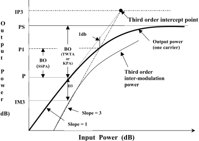
Both conceptually and in terms of hardware required, FDMA is relatively simple. Since a satellite transponder is a non-linear device, for multiple carriers, this nonlinearity generates harmonics that produce inter-modulation interference among neighbouring channels. To mitigate this effect, a reduction in input power, termed ‘backoff”, is necessary in order to operate in the linear portion of the transponder output vs. input power characteristics so that inter-modulation is reduced to an acceptable level. (See Figure 6. below).
As for TDMA, backoff is not necessary, which is a major advantage since at any given time a single user occupies the whole bandwidth of the transponder. Consequently its output power is greater than with FDMA. TDMA also offers more flexibility in that with relatively simple changes to software user allocation can be changed.
Figure 6. HPA Output Power vs. Input Power Characteristic
Source: Via Satellite (October 1998)
2.6.3 Bandwidth
There are numerous measures of bandwidth of which ‘Noise bandwidth’ is one and ‘Occupied bandwidth’ is another. The latter is the bandwidth required for the signal to pass through a band-limited filter. In an FDMA system, it is the occupied bandwidth that determines the system capacity. The occupied bandwidth is about 1.2 times the noise bandwidth.
A third measure of bandwidth is the null-to-null bandwidth. This is the width
D3
Third order inter-modulation power
BO (SSPA)
BO
(TWTA or KPA)
1db
Third order intercept point
Output power (one carrier)
Slope = 1
P
P1
Slope = 3
IP3 PS IM3 O u t p u t P o w e r