R E V I E W
Open Access
A systematic review of enhanced (or engineered)
geothermal systems: past, present and future
Katrin Breede
*, Khatia Dzebisashvili, Xiaolei Liu and Gioia Falcone
* Correspondence:katrin.breede@ tu-clausthal.de
Institute of Petroleum Engineering, Clausthal University of Technology, Agricolastraße 10,
Clausthal-Zellerfeld 38678, Germany
Abstract
Enhanced (or engineered) geothermal systems (EGS) have evolved from the hot dry
rock concept, implemented for the first time at Fenton Hill in 1977. This paper
systematically reviews all of the EGS projects worldwide, based on the information
available in the public domain. The projects are classified by country, reservoir type,
depth, reservoir temperature, stimulation methods, associated seismicity, plant
capacity and current status. Thirty five years on from the first EGS implementation,
the geothermal community can benefit from the lessons learnt and take a more
objective approach to the pros and cons of
‘
conventional
’
EGS systems.
Keywords:
Enhanced geothermal system, Engineered geothermal system, Hot dry
rock, Conventional EGS, EGS database worldwide
Review
The currently used term
‘
enhanced or engineered geothermal system
’
(EGS) has its
roots in the early 1970s when a team from Los Alamos National Laboratories began
the hot dry rock (HDR) project at Fenton Hill (Cummings and Morris 1979; Tester
et al. 1989; Brown 1997; Duchane 1998). The concept is described in Potter et al.
(1974). HDR was also known as hot fractured rock because of either the need to
frac-ture the virtually impermeable formations or the presence of natural fracfrac-tures in the
hot reservoir (Wyborn et al. 2005; Goldstein et al. 2011) or as hot wet rock (HWR)
when it was established that the formations were not completely dry but contained
some fluids. The European EGS project at Soultz-sous-Forêts in France is an example
of a HWR reservoir (Duchane 1998). Further nomenclature encountered in the
litera-ture include stimulated geothermal system, deep heat mining (Häring and Hopkirk
2002; Häring 2007) and deep earth geothermal. All of the above usually imply the use
of petrothermal systems (Ilyasov et al. 2010; Gebo NDS 2012a).
Schulte et al. (2010) defined the typical geological settings for EGS, varying from
ig-neous (e.g. Iceland), metamorphic (e.g. Lardarello, Italy), magmatic (e.g. Soultz, France)
and sedimentary (e.g. Groß Schönebeck and Horstberg, Germany).
According to Potter et al. (1974), the most suitable rock type for HDR is granite or
other crystalline basement rock; temperatures should vary from 150°C to 500°C at
depths in the order of 5 to 6 km, with an average flow rate over a 10-year reservoir
lifetime of 265 l/s, with hydraulic fracturing achieving a contact surface area of
ap-proximately 16 km
2, an average thermal capacity of 250 MW
ththat could be obtained
from the surface heat exchanger, and with pressurized water entering at 280°C and
© 2013 Breede et al.; licensee Springer. This is an open access article distributed under the terms of the Creative Commons Attribution License (http://creativecommons.org/licenses/by/2.0), which permits unrestricted use, distribution, and reproduction in any medium, provided the original work is properly cited.
Breedeet al. Geothermal Energy2013,1:4
leaving at 65°C. Based on these criteria, the potential electrical power that could be
generated might amount to 50 MW
eat a net efficiency of 20%.
Over the years, different definitions of EGS have been proposed, covering a broad
variety of rock types, depth, temperature, reservoir permeability and porosity, type of
stimulation technique involved, etc. Below are four examples of recent EGS definitions
in the public domain.
1. The Massachusetts Institute of Technology (MIT) led an interdisciplinary panel
which defined EGS as
‘
engineered reservoirs that have been created to extract
economical amounts of heat from low permeability and/or porosity geothermal
resources. For this assessment, this definition has been adapted to include all
geothermal resources that are currently not in commercial production and require
stimulation or enhancement. EGS would exclude high-grade hydrothermal but
include conduction dominated, low permeability resources in sedimentary and
basement formations, as well as geopressured, magma and low grade, unproductive
hydrothermal resources. Co-produced hot water from oil and gas production is
included as an unconventional EGS resource type that could be developed in the
short term and possibly provide a first step to more classical EGS exploitation
’
(MIT et al.
2006a
).
2. The Australian Geothermal Reporting Code Committee considered EGS as
‘
a body
of rock containing useful energy, the recoverability of which has been increased by
artificial means such as fracturing
’
(AGRCC
2010
).
3. Williams et al. (
2011
) proposed that
‘
EGS comprise the portion of a geothermal
resource for which a measureable increase in production over its natural state is or
can be attained through mechanical, thermal, and/or chemical stimulation of the
reservoir rock. In this definition, there are no restrictions on temperature, rock type
or pre-existing geothermal exploitation
’
.
4. The BMU (
2011
) defines enhanced geothermal systems as creating or enhancing a
heat exchanger in deep and low permeable hot rocks using stimulation methods.
Following BMU's definition, EGS embraces not only HDR but also deep heat
mining, hot wet rock, hot fractured rock, stimulated geothermal systems, and
stimulated hydrothermal systems.
Clearly, the geothermal community lacks a universal definition of EGS, which may
simply be taken as
‘
unconventional geothermal systems
’
, diverging significantly from
the initial HDR concept. This lack of clarity may constitute a potential obstacle to the
implementation of tailored subsidy programmes.
competent crystalline formations, through that of open-hole massive injection in
naturally fractured crystalline formations and finally to the proposed multi-zone
massive injection (with the objective of generating multiple wing cracks) in naturally
fractured crystalline formations. As this review does not aim at a project-by-project
evaluation of the geomechanics that occur during EGS stimulation, the modified
MIT definition is considered to be suitable for generating the database proposed in
this study.
Geopressured and magma systems were left out from this review because they
typically have been excluded from past EGS cataloguing attempts, such as those
proposed by European Geothermal Energy Council (EGEC) (2012) and GtV (2013).
EGS milestones
During the last four decades, there have been some key milestones towards the
devel-opment of EGS for heat production and electricity generation. The information that
follows is based on the report by Tenzer (2001), supplemented by additional
information:
1970: Proposals for the first EGS worldwide in Fenton Hill, Los Alamos, USA.
1973: First EGS experiments in Fenton Hill.
1974 to 1977: Feasibility studies for EGS projects in Japan.
1975: Start of preparations for the first scientific EGS pilot plant in Bad Urach,
Germany.
Since 1977: EGS feasibility studies for shallow depths at Falkenberg, Germany,
Camborne School of Mines, Cornwall in the UK and Le Mayet, France.
1977: EGS Bad Urach - drilling starts.
1980 to 1986: EGS Bad Urach - deepening of the borehole to 3,488 m at 147°C and
hydraulic tests for single borehole system.
1984 to 1985: Start of EGS; Neustadt-Glewe, as a pilot project for low enthalpy
energy; to date, this is the warmest accessed hot water reservoir in Northern
Germany.
1986: Start of the German-French EGS project at Soultz-sous-Forêts, France, as a
joint European research EGS pilot plant.
1986 to 1991: First EGS experiments in Hijori and other locations in Japan.
1987: EGS Soultz - began drilling the first borehole to 2,000 m at 140°C and started
the investigation of the crystalline basement in the Rhine-Graben.
1989: EGS Soultz - UK joins the project; formation of an industrial consortium for
organized planning and operation of an EGS project in Europe.
1990: EGS Soultz - drilling of a second 2,000-m deep borehole and deepening of
the first borehole to 3,500 m depth (at 160°C); geothermal reservoir identification;
the second borehole was used as seismic observation borehole.
1991 to 1996: EGS Bad Urach - deepening of the borehole to a depth of 4,445 m at
a temperature of 172°C; also performed intense borehole measurement programme.
1994
–
1995: EGS Soultz - deepening of the second borehole to a depth of 3,876 m,
followed by a production test which saw the first steam production in Middle
Europe from crystalline rocks; using massive stimulation and circulation tests
Breedeet al. Geothermal Energy2013,1:4 Page 3 of 27
with seismic monitoring and development of the downhole heat exchanger,
a thermal power of 8 MW was achieved.
1996: Start of deep heat mining project in Basel, Switzerland - a pilot project for
EGS in a modern urban environment.
1996 to 1997: EGS Bad Urach - development of a downhole heat exchanger by
massive hydraulic fracturing; the largest EGS created worldwide; long-term
(4 months) hydraulic circulation test; a thermal power of 11 MW was achieved.
1998 to 2000: EGS Soultz - deepening of the second borehole to 5,060 m at 201°C;
hydraulic stimulation and seismic monitoring.
2001: Start of EGS Groß-Schönebeck, Germany, which was the first
in situ
geothermal laboratory for developing techniques for the exploration and usage of
geothermal energy.
2003: Start of EGS Cooper Basin, Australia - the largest demonstration EGS project
in the world.
2003: Test of new single well concept in Genesys Horstberg, Germany.
2003: Start of EGS Landau - the first geothermal combined heat power plant to be
connected to the grid; the one and only EGS project in a German town.
2004: Start of Unterhaching, Germany, the first geothermal project in the
Bavarian Molasse Basin where, in addition to heat supply, electricity
generation was also achieved; first Kalina power plant in Germany; first
project worldwide with a private sector insurance for geological risk in deep
boreholes.
2005: Start of EGS Paralana trying to implement an underground heat exchanger
called
‘
heat exchanger within an insulator (HEWI)
’
concept (heat exchanger within
the insulator) (Petratherm
2012
).
2006/2007: Deep heat mining project in Basel stopped due to repeated severe
induced seismicity events; the project was permanently abandoned in 2009.
2007: First binary geothermal plant in France at EGS Soultz (with ORC plant).
2009: New law for renewable energies in Germany - electricity generation and
supply to the power net gets more financial support.
2009: Start of EGS GeneSys Hannover, Germany, as a single well concept.
2009: Start of EGS St. Gallen, Switzerland.
2010: Implementation of new
‘
side-leg
’
concept in the EGS project Insheim
(Germany); forked injection well shall reduce induced seismicity
(Insheim
2012
).
2011: EGS GeneSys Hannover put on hold due to salt deposition in the single well.
2011: Guidelines for
‘
seismic surveillance
’
for Germany published by Bundesverband
Geothermie.
2012: Switzerland decides to support deep geothermal projects.
2012: EGS Insheim connected to the power net.
2013: EGS Habanero successfully commissioned, with generation of 1 MW
eof
power; first EGS project in Australia generating electricity.
Systematic overview of past and present EGS projects worldwide
The following review should not be considered exhaustive as it is based exclusively
on the information available in the public domain. Yet, to the authors' knowledge, this
is the first public attempt to formally collate a large database of information on EGS
worldwide, from the first HDR project at Fenton Hill in 1974 to date.
The objective of this review is to present key information on past and present EGS
experience worldwide, from which key lessons can be learnt for the future.
The 31 EGS projects identified during this review are classified by country, reservoir
type, depth, reservoir and wellhead temperature, stimulation methods, induced
seismi-city and radioactivity, plant capaseismi-city, flow rate and current status.
The 31 projects are divided into four different groups:
Table 1 comprises basic information about EGS projects that are still under
develop-ment. It does not include pending commercial projects that are either at the status of
raising funds (e.g. Munster in Germany and Eden in the UK) or still need governmental
approval.
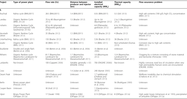
Tables 2 and 3 present projects that are already in the power generation phase.
Table 4 gives information about experimental projects that were developed to
test single phase of an EGS project rather than the whole process to generate
electricity.
Table 5 presents information on projects that are aimed for electricity generation but
were abandoned due to various problems. Input information was drawn from different
sources available in the public domain; all of which are cited in the titles of the tables.
This grouping criteria allow the reader to have an immediate overview of past vs.
current vs. future EGS activities, better appreciate the challenges faced by EGS
(tech-nical, economic and related to public acceptance), develop a feeling for the level of
re-search and development efforts put into EGS
vis-à-vis
the desire to achieve worldwide
commercialisation of the concept.
Note that in the tables,
‘
microseismic
’
refers to seismic activity less than 3.5 on the
Richter scale and is used for those cases when no further details on recorded seismicity
could be found in the literature. See the following paragraphs for more discussions on
induced seismicity in EGS projects.
When
‘
thermal capacity
’
is quoted next to
‘
installed electrical capacity
’
, this implies a
combined heat and power project.
Under
‘
stimulation
methods
’
,
the
terms
‘
hydraulic
fracturing
’
,
‘
hydraulic
’
,
‘
hydroshearing
’
,
‘
shear
’
and
‘
hydraulic stimulation
’
are taken directly as quoted by the
cited sources. The authors of this manuscript have not performed an independent
review or assessment of the specific stimulation methods implemented in or planned
for each individual project, as this falls outwith the scope of this broader EGS review.
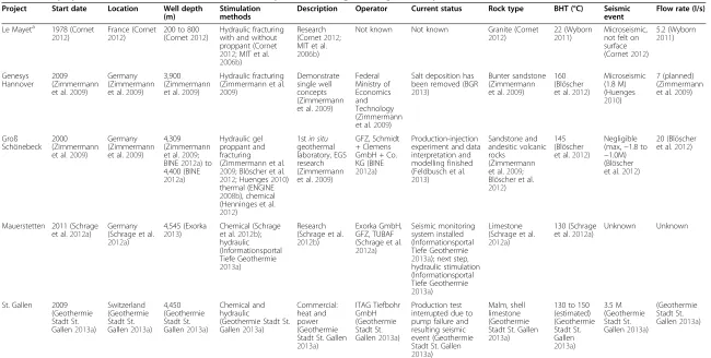
Overall, the tables above capture a detailed database of 31 EGS projects worldwide.
Based on the tables, the following plots provide a way to extract trends and common
characteristics of EGS.
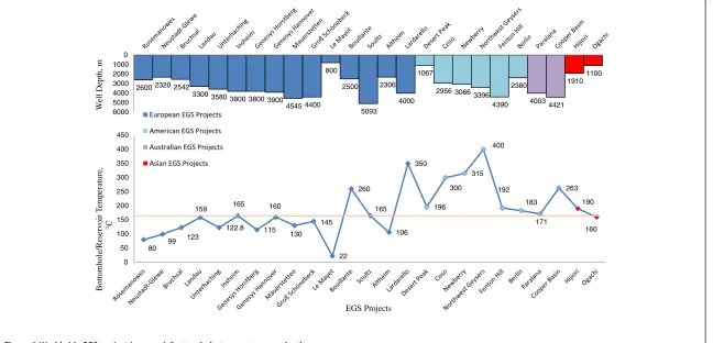
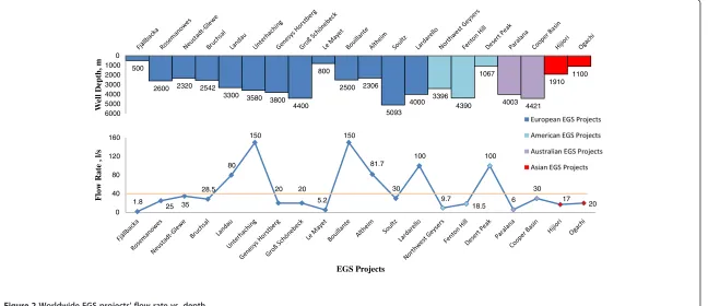
As illustrated in Figure 1, most of the European EGS projects' reservoir/
bottomhole temperatures are lower than 165°C, with the exception of Lardarello
and Bouillante. Compared to Europe, the average EGS reservoir/bottomhole
tem-peratures in America, Australia and Asia are higher although the well depths are
comparable. Note that only 25 projects are displayed in Figure 1; the remaining 6
Breedeet al. Geothermal Energy2013,1:4 Page 5 of 27
Table 1 EGS projects (R&D and commercial) still under development and not generating electricity
Project Start date Location Well depth (m)
Stimulation methods
Description Operator Current status Rock type BHT (°C) Seismic event
Flow rate (l/s)
Le Mayeta 1978 (Cornet
2012)
France (Cornet
2012)
200 to 800 (Cornet2012)
Hydraulic fracturing with and without proppant (Cornet
2012; MIT et al.
2006b)
Research (Cornet2012; MIT et al.
2006b)
Not known Not known Granite (Cornet
2012)
22 (Wyborn
2011)
Microseismic, not felt on surface (Cornet2012)
5.2 (Wyborn 2011) Genesys Hannover 2009 (Zimmermann et al.2009)
Germany (Zimmermann et al.2009)
3,900 (Zimmermann et al.2009)
Hydraulic fracturing (Zimmermann et al.
2009)
Demonstrate single well concepts (Zimmermann et al.2009)
Federal Ministry of Economics and Technology (Zimmermann et al.2009)
Salt deposition has been removed (BGR
2013)
Bunter sandstone (Zimmermann et al.2009)
160 (Blöscher et al.2012)
Microseismic (1.8 M) (Huenges 2010) 7 (planned) (Zimmermann et al.2009)
Groß Schönebeck
2000 (Zimmermann et al.2009)
Germany (Zimmermann et al.2009)
4,309 (Zimmermann et al.2009; BINE2012a) to 4,400 (BINE
2012a)
Hydraulic gel proppant and fracturing (Zimmermann et al.
2009; Blöscher et al.
2012; Huenges2010) thermal (ENGINE
2008b), chemical (Henninges et al.
2012)
1stin situ
geothermal laboratory, EGS research (Zimmermann et al.2009)
GFZ, Schmidt + Clemens GmbH + Co. KG (BINE
2012a)
Production-injection experiment and data interpretation and modelling finished (Feldbusch et al.
2013)
Sandstone and andesitic volcanic rocks
(Zimmermann et al.2009; Blöscher et al.
2012)
145 (Blöscher et al.2012)
Negligible (max,−1.8 to −1.0M) (Blöscher et al.2012)
20 (Blöscher et al.2012)
Mauerstetten 2011 (Schrage et al.2012a)
Germany (Schrage et al.
2012a)
4,545 (Exorka
2013)
Chemical (Schrage et al.2012b); hydraulic (Informationsportal Tiefe Geothermie
2013a)
Research (Schrage et al.
2012b)
Exorka GmbH, GFZ, TUBAF (Schrage et al.
2012a)
Seismic monitoring system installed (Informationsportal Tiefe Geothermie
2013a); next step, hydraulic stimulation (Informationsportal Tiefe Geothermie
2013a)
Limestone (Schrage et al.
2012a)
130 (Schrage et al.2012a)
Unknown Unknown
St. Gallen 2009 (Geothermie Stadt St. Gallen2013a)
Switzerland (Geothermie Stadt St. Gallen2013a)
4,450 (Geothermie Stadt St. Gallen2013a)
Chemical and hydraulic
(Geothermie Stadt St. Gallen2013a)
Commercial: heat and power (Geothermie Stadt St. Gallen
2013a)
ITAG Tiefbohr GmbH (Geothermie Stadt St. Gallen2013a)
Production test interrupted due to pump failure and resulting seismic event (Geothermie Stadt St. Gallen
2013a)
Malm, shell limestone (Geothermie Stadt St. Gallen
2013a)
130 to 150 (estimated) (Geothermie Stadt St. Gallen 2013a) 3.5 M (Geothermie Stadt St. Gallen2013a)
(Geothermie Stadt St. Gallen2013a)
Table 1 EGS projects (R&D and commercial) still under development and not generating electricity
(Continued)
Newberry 2010 (Cladouhos et al.2012)
USA (Cladouhos et al.2012)
3,066 (BLM
2012)
Hydroshearing, multi-zone isolation techniques (Cladouhos et al.
2012) Demonstration for EGS stimulation/ research (Cladouhos et al.2012)
AltaRock Energy, Davenport Newberry (Cladouhos et al.2012)
Stimulation started successfully (Informationsportal Tiefe Geothermie 2012) Volcanic rocks (Fittermann1988)
315 (Cladouhos et al.2012)
Microseismic (Cladouhos et al.2012)
Unknown
Northwest Geysers
In 1980s (Garcia et al.
2012)
USA (Romero et al.1995)
3,396 (Garcia et al.2012)
Thermal fracturing (Walters2013)
Demonstration/ research (Garcia et al.
2012)
Calpine Corporation (Garcia et al.
2012)
Stimulation stage (5 MW of potential production) (Walters
2013)
Metasedimentary rocks (greywacke) (Romero et al.
1995; Garcia et al.
2012)
About 400 (Garcia et al.
2012)
Microseismic (0.9 to 2.87 M) (Garcia et al.2012; Walters2013)
9.70 (Garcia et al.2012)
Paralana 2005 (Petratherm 2012) Australia (Petratherm 2012) 4,003 (Petratherm 2012) Hydraulic (Petratherm2012)
Commercial power development (Petratherm 2012) Petratherm, Beach Energy (Petratherm 2012)
Drilling of Paralana 3, submit funding application (Petratherm2012)
Metasediments, granite (Petratherm2012)
171 (Petratherm
2012)
Microseismic ≤2.6 M (Petratherm
2012)
Up to 6 (ENGINE
2008b)
GFZ, German Research Centre for Geosciences; TUBAF, Technische Universität und Bergakademie Freiberg (Germany); BHT, bottomhole temperature;a
Note that little and contrasting information was found in the open domain concerning the project‘Le Mayet’. Some sources say that it was operational from 1984 till 1987 (Evans2011). Others (MIT et al.2006b) report that it was still ongoing as of 2006 and having a BHT of 33°C instead of the 22°C reported in the table.
Table 2 Ongoing EGS projects (R&D and commercial) generating electricity
Project Start date Location Well depth (m) Stimulation methods
Description Operator Rock type Reservoir
temperature (°C) Seismic event A. Bruchsal 1,983 (BMU2011) Germany (BMU2011)
1,874 to 2,542 (BMU2011)
Unknown Commercial (Enbw2013) EnBW, EWB (KIT2013) Bunter Sandstone (KIT2013)
123 (Rettenmaier
2012)a;
Microseismic (KIT2013)
Landau 2003 (BINE
2012d)
Germany (Baumgärtner
2012)
3,170 to 3,300 (Baumgärtner
2012)
No stimulation for producer; hydraulic for injector (Baumgärtner
2012)
First implementation of EGS technology in Germany (BINE
2012d); first and only EGS in town in (D) (Baumgärtner2012)
BESTEC, Geox (Baumgärtner2012)
Granite (Lacirignola and Blanc2012)
159 (Baumgärtner
2012)a
Microseismic (≤2.7 M) (Baumgärtner
2012), felt by residents Insheim 2007 (Insheim 2012) Germany (Insheim 2012)
3,600 to 3,800 (LGB-rlp2012)
Yes (Baumgärtner
2012)
New concept, side-leg injection well (BINE2012b)
Pfalzwerke geofuture GmbH (Pfalzwerke-geofuture2012; BINE
2012b) Keuper, perm, bunter sandstone, granite (Baumgärtner 2012) 165 (LGB-rlp 2012)
M: 2.0 to 2.4 and microseismic (Groos et al.
2012) Neustadt-Glewe 1984 (BMU 2011) Germany (Bracke2012)
2,320 (Bracke
2012)
Unknown Commercial, pilot plant for low enthalpy (BMU2011)
WEMAG AG, Stadt Neustadt-Glewe, Geothermie Neubrandenburg GmbH (BMU2011) Sandstone (BMU 2011)
99 (GtV2013)a Unknown
Unterhaching 2004 (BMU2011)
Germany (Bracke2012)
3,350 to 3,580 (Bracke2012)
Acidizing (BMU2011)
First Kalina power plant in Germany (BINE2012c)
Geothermie
Unterhaching GmbH & Co. KG, Rödl & Partner GbR (BINE2012c)
Limestone (Dumas2010)
123 (Bracke
2012)a Unknown
Soultz 1987 (MIT et al.
2006b)
France (Genter2012)
5,093 (MIT et al.
2006d)
Hydraulic fracturing and acidizing (MIT et al.2006d)
Research and demonstration (Genter2012)
European cooperation project (MIT et al.
2006d)
Granite (MIT et al.
2006d)
165 (BMU
2011)
Microseismic (M =−2 to 2.9) (Genter2012)
Bouillante 1963/1996 (Bertini et al.2006)
France (Guadeloupe) (Bertini et al.
2006)
1,000 to 2,500 (Bertini et al.
2006)
Thermal cracking (Bertini et al.2006)
Commercial (Bertini et al.2006) Geothermie Bouillante, CFG-Services, BRGM, ORKUSTOFNUN, COFOR (Bertini et al.2006)
Volcanic lavas and tuffs (Bertini et al.2006)
250 to 260 (Bertini et al.
2006)
Microseismic (Sanjuan et al.
Table 2 Ongoing EGS projects (R&D and commercial) generating electricity
(Continued)
Altheim 1989 (Pernecker 1999) Austria (Bloomquist 2012)2,165 to 2,306 (Bayerisches Landesamt für Wasserwirtschaft
2011)
Acidizing (Pernecker1999), hydraulic stimulation (ENGINE2008b)
Commercial (Pernecker1999) Municipality of Altheim, Terrawat (Pernecker 1999) Limestone (Bayerisches Landesamt für Wasserwirtschaft 2011) 106 (Bloomquist 2012) Unknown Lardarello 1970 (Cappetti 2006) (1904) Italy (ENGINE 2008b)
2,500 to 4,000 (Bertini et al.
2006)
Hydraulic and thermal stimulation (ENGINE2008b)
Research and demonstration (Cappetti2006) and commercial
ENEL Green Power (Lazzarotto and Sabatelli
2005)
Metamorphic rocks (ENGINE
2008b)
300 to 350 (ENGINE
2008a)a
≤3.0 M (Bromley2012)
Coso 2002
(Häring
2007)
USA (Häring
2007)
2,430 to 2,956 (Julian et al.2009)
Hydraulic, thermal and chemical (Rose et al.2004)
Research and development (Häring2007)
Coso Operating Company (EGS Coso
2013)
Diorite, granodiorite, granite (Rose et al.2004)
≥300 (EGS Coso2013)
≤2.8 M (Julian et al.2009)
Desert Peak 2002 (MIT
2006c)
USA (MIT et al.2006c)
About 1,067 (Chabora et al.
2012)
Shear, chemical, hydraulic (Davatzes et al.2012)
Research and development (Davatzes et al.2012)
Ormat, GeothermEx (Val Pierce2011)
Volcanic and metamorphic rocks (Chabora et al.2012)
179 to 196 (Chabora et al.
2012)
Microseismic: −0.03 to 1.7 (Chabora and Zemach2013)
Berlín 2001
(Bommer et al.2006)
El Salvador (Rodríguez
2003)
2,000 to 2,380 (Rodríguez2008)
Hydraulic fracturing and chemical (Rodríguez2003)
Developing EGS project in a geothermal field (Rodríguez
2003)
Shell International (Rodríguez2003), LaGeo (Bommer et al.2006)
Volcanic rocks (Häring2007)
183 (Bommer et al.2006)
≤4.4 M (Bommer et al.
2006)
Cooper Basin 2003 (Majer et al.2007)
Australia (Majer et al.
2007)
4,421 (Majer et al.
2007)
Hydraulic (Majer et al.2007; Holl
2012)
Largest demonstration project in the world (Stephens and Jiusto
2010)
Geodynamics Ltd. (Majer et al.2007; Geodynamics2013)
Granite (Majer et al.2007)
242 to 278 (Geodynamics
2013)
≤3.7M (Majer et al.2007)
Hijiori 1985
(Sasaki
1998)
Japan (Sasaki
1998)
1,805 to 1,910 (Sasaki1998)
Hydraulic fracturing (Sasaki1998)
Developing EGS technologies (Sasaki1998)
Japan's new energy (DiPippo2012a), NEDO (Sasaki1998)
Granodiorite (Sasaki1998)
190 (DiPippo
2012a)
Microseismic (Sasaki1998)
a
Reservoir temperature not available, BHT is used instead.
Table 3 Ongoing EGS projects (R&D and commercial) generating electricity
Project Type of power plant Flow rate (l/s) Distance between producer and injector (km)
Installed electrical capacity (MWe)
Thermal capacity (MWth)
Flow assurance problem
B.
Bruchsal Kalina cycle (BMU2011) 28.5 (BMU2011) 1.4 (BMU2011) 0.55 (BMU2011) 5.5 (GtV2013) High salt contents (100 g/l); high CO2concentration (BMU2011)
Landau Organic Rankine Cycle (BINE2012d)
70 to 80 (Baumgärtner
2012)
1.5 (Bracke2012) Up to 3.6 (Baumgärtner2012)
2 to 5 (Baumgärtner
2012)
Unknown
Insheim Organic Rankine Cycle (Informationsportal Tiefe Geothermie2013b)
65 to 85 (planned) (Pfalzwerke-geofuture
2012)
Unknown 4.8
(Pfalzwerke-geofuture2012)
6 to 10 (Pfalzwerke-geofuture2012)
Unknown
Neustadt-Glewe
Organic Rankine Cycle (Bracke2012)
35 (Bracke2012) 1.5 (BMU2011) 0.21 (Bracke2012) 4 (Bracke2012) High salt content, high gas concentration (Bracke2012)
Unterhaching Kalina cycle (BMU2011) 150 (Bracke2012) 4.5 (Bracke2012) 3.36 (Bracke2012) 38 (Bracke2012) Unknown Soultz Organic Rankine Cycle
(BMU2011)
30 (BMU2011) 0.6 (BMU2011) 1.5 (BMU2011) Non-scheduled (Dumas
2010)
Corrosion due to high salt contents (BMU2011)
Bouillante Double and single flash (Bertini et al.2006)
150 (Bertini et al.2006) 0.5 (Bertini et al.2006) 15 (Bertini et al.
2006)
Unknown Unknown
Altheim Organic Rankine cycle (Bayerisches Landesamt für Wasserwirtschaft2011)
81.7 (Bayerisches Landesamt für Wasserwirtschaft2011)
1.7 (Bayerisches Landesamt für Wasserwirtschaft2011)
1.0 (Bloomquist
2012)
12.4 (Bayerisches Landesamt für Wasserwirtschaft2011)
Clogging by a mixture consisting of stone material and bentonite (Pernecker1999)
Lardarello Not known 100 (Cappetti2006) Variable: generally > 0.5 (ENGINE2008a)
700 (ENGINE2008b) Not known Highly corrosive, total loss of circulation when very high permeability fracture zones are encountered (ENGINE2008b)
Coso Unknown Unknown 1.4 (Julian et al.2009) 240 (Karner2005) Unknown Unknown
Desert Peak Unknown 100 (Chabora and
Zemach2013)
Unknown 1.7 (additional)
(Chabora and Zemach2013)
Unknown Wellbore instability due to chemical stimulation (Chabora et al.2012)
Berlín Binary power plant (Prevost2004)
Unknown Unknown 54 (Bommer
et al.2006)
56 (Rodríguez2000) Unknown
Cooper Basin Unknown 30 (Holl2012) Unknown 1 (Geodynamics
2013)
Unknown Unknown
Hijiori Binary Power Plant (DiPippo2012a)
17 (Sasaki1998) 0.038 to 0.063 (DiPippo2012a)
0.13 (DiPippo2012a) 8 (DiPippo2012a) High water losses (Johansson et al.1993), precipitation of anhydrite (DiPippo2012a)
Energy
2013,
1
:4
rgy-journa
l.com/conte
projects (St. Gallen, Fjällbacka, Falkenberg, The Southeast Geysers, Basel and Bad
Urach) are excluded because reservoir/bottomhole temperature data could not be
found in the public domain or are only estimated in the case of St. Gallen.
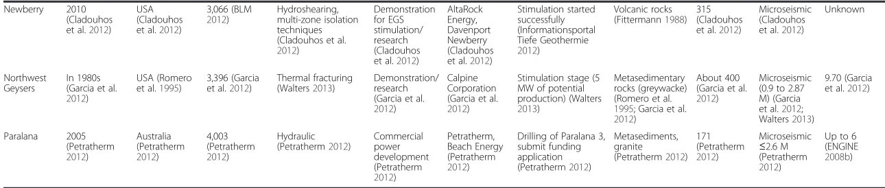
The relationship shown in Figure 2 points out that most EGS activities are
oper-ated at flow rates lower than 40 l/s. Note that only 20 projects are displayed in
Figure 2; the remaining 11 projects (Genesys Hannover, Insheim, Mauerstetten,
Newberry, Coso, Berlín, Falkenberg, The Southeast Geysers, Basel, Bad Urach and
St. Gallen) are excluded because flow rate data could not be found in the public
domain.
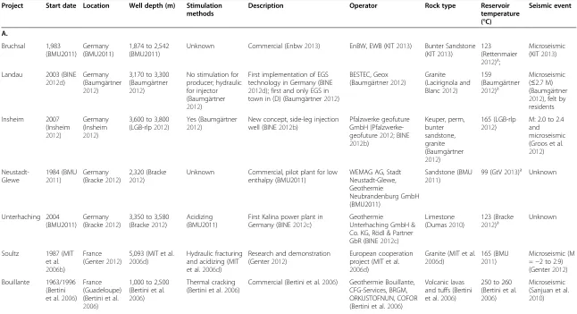
Figure 3 displays EGS projects classified on the basis of rock types. Although it
ap-pears that EGS activities can be implemented in any of the three major groups of rocks
on earth, most projects are developed in igneous rocks, following the original HDR
concept.
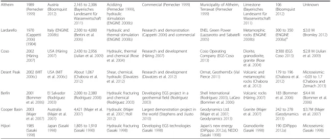
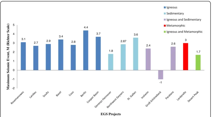
The recorded maximum magnitudes of induced seismic events associated with
the development of EGS projects worldwide are shown in Figure 4. Originally, the
Richter scale was developed as a mathematical device to compare local earthquake
sizes. The magnitude is defined as the logarithm of the wave amplitude recorded
by seismographs. At that time, the smallest measurable earthquakes were assigned
with values close to zero. However, due to the higher accuracy of modern
seismo-graphs, the Richter scale now measures earthquakes having negative magnitudes.
Majer et al. (2007) reported that
‘…
To date, the maximum observed earthquakes
attributed to EGS operations have been magnitude 3.0 to 3.7 and the largest
geo-thermal injection-related event was magnitude 4.6
’
. Later, Majer et al. (2013) also
stated that for EGS, earthquakes are typically smaller than M 3.5 (M representing
the momentum magnitude in this context). According to EGEC (2013),
microseis-mic activity is less than 3.5 on the Richter scale. Only the projects with published
induced seismic magnitude are displayed in Figure 4; the remaining 16 projects
(Le Mayet, Mauerstetten, Newberry, Bruchsal, Neustadt-Glewe, Unterhaching,
Bouillante, Altheim,, Hijiori, Genesys Horstberg, Fjällbacka, Fenton Hill, Ogachi,
Bad Urach, Falkenberg and The Southeast Geysers), most of which have been
reported to suffer from microseismicity, are omitted due to lack of explicit seismic
data.
Stimulation methods that are applied in EGS developments are summarized in
Figure 5, which reveals that hydraulic stimulation is the most commonly used
method, independently of the rock type concerned. In addition, there are relatively
few cases where chemical or thermal stimulation technologies are applied. This
often leads to the assumption that the EGS definition only applies to hydraulically
fractured systems.
The installed electrical and thermal capacity of EGS projects are summarized in
Figure 6. Since EGS is still a developing concept, the database contains only 14 projects
carried out with electricity generation. Note that the thermal capacities of Bouillante,
Soultz, Lardarello, Desert Peak, Cooper Basin and Coso are missing as data could not
be found in the public domain. The variation of production scale causes great capacity
differences among the projects.
Figure 7 shows the rock type and well depth of all the studied EGS projects
worldwide.
Breedeet al. Geothermal Energy2013,1:4 Page 11 of 27
Results and discussions
From the information provided in the tables and the plots shown earlier, it appears that
EGS projects currently under development are still on the learning curve, overcoming
problems, gaining experience and trying to introduce advanced technology; the projects
already concluded provide relevant history and analogy for upcoming developments
and the projects that have been temporarily halted or abandoned give an insight into
is-sues that must be avoided in the future.
Below are field cases where breakthrough methodologies were first implemented to
validate the EGS concept. Unplanned events and issues that needed addressing in order
to ensure feasibility and commerciality of EGS are discussed, and the corresponding
lessons learnt are highlighted.
The
‘
Paralana
’
project will use a new concept called the HEWI (Petratherm
2012
).
The
‘
Genesys
’
project was the first project worldwide testing a single well
concept. Technical feasibility of the concept was proved by the
‘
Genesys
Horstberg
’
project. The subsequent
‘
Genesys Hannover
’
aimed to use
geothermal energy to heat the building complex of the Geozentrum Hannover
(Tischner et al.
2010
). The project has currently solved the problem of salt
deposition, which has led to a suspension of the production test (Genesys
2012
). This single well concept has the advantage of lower drilling costs as only
one wellbore is needed to be drilled. However, since the circulating fluid moves
through fractures, it is in direct contact with the rock formation, which leads
to salt deposition risk. This experience has taught the geothermal community
that flow assurance needs to be addressed ahead of time to prevent issues
triggered by the chemical interaction between the injected fluid and the
receiving rock, which can impair the overall success of an EGS project.
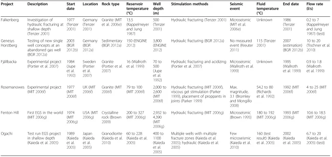
Table 4 Concluded experimental EGS projects (without power generation)
Project Description Start date
Location Rock type Reservoir temperature (°C)
Well depth (m)
Stimulation methods Seismic event
Fluid temperature (°C)
End date Flow rate (l/s)
Falkenberg Investigation of hydraulic fracturing at shallow depth (Tenzer2001)
1977 (Tenzer 2001) Germany (Tenzer 2001) Granite (MIT et al.2006e)
13.5 (Kappelmeyer and Jung 1987) 500 (Tenzer 2001)
Hydraulic fracturing (Tenzer2001) Microseismic (MIT et al.
2006e)
Unknown 1986
(Tenzer
2001)
0.2 to 7 (Kappelmeyer and Jung
1987) (test)
Genesys Horstberg
Testing of new single well concepts at an abandoned gas well (BGR2012a)
2003 (BGR 2012b) Germany (BGR 2012a) Sedimentary (BGR2012a)
150 (ENGINE
2012)
3,800 (ENGINE
2012)
Hydraulic fracturing (BGR2012a) No measured event (Kreuter 2011) 115 (Tenzer 2001) 2007 (estimation) (BGR2012b)
10 to 20 (Tischner et al.
2010)
Fjällbacka Experimental project (Portier et al.2007)
1984 (Jupe et al. 1992) Sweden (Portier et al. 2007) Granite (Portier et al.
2007)
16 (Wallroth et al.1999)
70 to 500 (Jupe et al.
1992)
Hydraulic fracturing and acidizing (Portier et al.2007)
Microseismic (Wallroth et al.
1999)
Unknown 1995
(Wallroth et al.1999)
0.9 to 1.8 (Wallroth et al.1999)
Rosemanowes Experimental project (MIT2006f)
1977 (MIT 2006f) UK (MIT 2006f) Granite (MIT 2006f)
79 to 100 (MIT2006f)
2,000 to 2,600 (MIT
2006f)
Hydraulic fracturing (MIT2006f), viscous gel stimulation (Parker
1999), placement of proppants in joints (Parker1999)
Max. magnitude, 3.1 (Bromley and Mongillo
2008)
54.2 to 80 (Richards et al.1992)
1992 (MIT
2006f)
4 to 25 (MIT
2006f)
Fenton Hill First EGS in the world (MIT2006g)
1974 (MIT 2006g) USA (MIT 2006g) Crystalline rock (Brown 2009)
200 to 327 (MIT2006g)
2,932 to 4,390 (MIT
2006g)
Hydraulic fracturing (MIT2006g) Microseismic (Brown1995)
180 to 192 (MIT2006g)
1993 (MIT
2006g)
10.6 to 18.5 (MIT2006g)
Ogachi Test run EGS project in shallow depth (Kaieda et al.2005)
1989 (Kaieda et al. 2005) Japan (Kaieda et al. 2005) Granodiorite (Kaieda et al.
2010)
60 to 228 (Kaieda et al.
2005) 400 to 1100 (Kaieda et al. 2005)
Multiple wells with multiple fracture zones (Kaieda et al.
2005); hydraulic (Kaieda et al.
2005)
Few microseismic (Kaieda et al.
2010)
160 (test result) (Kaieda et al.2005)
2002 (Kaieda et al.2005)
6.7 to 20 (Kaieda et al.
2005) (test)
The Altheim project in Austria uses a special working fluid, which was never used
before - a non-flammable, non-corrosive fluid with no ozone depletion activity
(Bloomquist
2012
).
The
‘
Fenton Hill
’
project was the first attempt to extract geothermal energy form
hot dry rocks with low permeability in the history of EGS (MIT et al.
2006g
). One
of the main lessons learnt from the Fenton Hill project is that an engineered hot
reservoir should first be created from the preliminary borehole and then by
connecting the enhanced reservoir and the injection borehole with the production
boreholes (Brown
2009
).
The
‘
Rosemanowes Quarry
’
project in the UK stemmed directly from the positive
results from Fenton Hill. One of the most significant lessons learnt from this
project is that natural fractures and engineered fractures are almost unrelated. The
natural fracture network plays a more important role compared with hydraulically
enhanced fractures (MIT et al.
2006f
). Also, as reported by Jung (
2013
), until then,
the basement had been regarded as a competent rock mass, realizing that in reality,
the basement contains open natural fractures even at great depth led to the
abandonment of the HDR multi-fracture concept and the adoption of the hydraulic
stimulation EGS concept.
The
‘
Fjällbacka
’
project in Sweden gives similar conclusions to the Rosemanowes
project, i.e. that naturally fractured systems dictate the results of reservoir
stimulation (Wallroth et al.
1999
).
The
‘
Falkenberg
’
project began in 1976 and was planned as a test site for HDR at
shallow depths to better understand the mechanical and hydraulic properties of
fractures (Kappelmeyer and Jung
1987
). A power generation phase was never
intended.
The
‘
Ogachi
’
project in Japan, a five-spot well pattern (four producers, one
injector), was planned to be used for geothermal energy extraction from a
shallow depth reservoir, but due to financial problems, the multiple
production well system was not tried out. However, several basic technologies
were successfully developed for general EGS activities through the project,
which were later applied in another EGS programme in the Cooper Basin,
South Australia in 2002 (Kaieda et al.
2005
).
The
‘
Basel
’
project in Switzerland saw induced seismic events - some exceeding 3.0
in magnitude - which led to its suspension (Ladner and Häring
2009
). The Basel
area has a history of natural seismic activity; the city was severely damaged by a 6.7
magnitude earthquake in 1356, the largest seismic event ever recorded in Central
Europe (Giardini
2009
). However, following a 3-year study after the seismic events
recorded in connection with the geothermal project activities, the Basel project was
cancelled. Induced seismicity associated with water injection and particularly
hydraulic fracturing activities (due to changing stress patterns in reservoir rocks)
has caused wide concern among the public (Majer et al.
2011
).
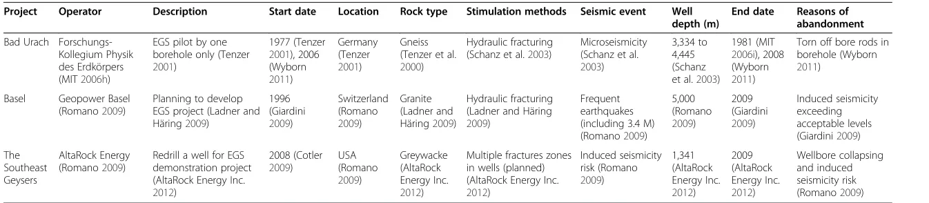
Table 5 Abandoned or on hold EGS projects
Project Operator Description Start date Location Rock type Stimulation methods Seismic event Well depth (m)
End date Reasons of abandonment
Bad Urach Forschungs-Kollegium Physik des Erdkörpers (MIT2006h)
EGS pilot by one borehole only (Tenzer
2001)
1977 (Tenzer
2001), 2006 (Wyborn
2011)
Germany (Tenzer
2001)
Gneiss (Tenzer et al.
2000)
Hydraulic fracturing (Schanz et al.2003)
Microseismicity (Schanz et al.
2003)
3,334 to 4,445 (Schanz et al.2003)
1981 (MIT
2006i), 2008 (Wyborn
2011)
Torn off bore rods in borehole (Wyborn
2011)
Basel Geopower Basel (Romano2009)
Planning to develop EGS project (Ladner and Häring2009)
1996 (Giardini
2009)
Switzerland (Romano
2009)
Granite (Ladner and Häring2009)
Hydraulic fracturing (Ladner and Häring
2009)
Frequent earthquakes (including 3.4 M) (Romano2009)
5,000 (Romano
2009)
2009 (Giardini
2009)
Induced seismicity exceeding acceptable levels (Giardini2009)
The Southeast Geysers
AltaRock Energy (Romano2009)
Redrill a well for EGS demonstration project (AltaRock Energy Inc.
2012)
2008 (Cotler
2009)
USA (Romano
2009)
Greywacke (AltaRock Energy Inc.
2012)
Multiple fractures zones in wells (planned) (AltaRock Energy Inc.
2012)
Induced seismicity risk (Romano
2009)
1,341 (AltaRock Energy Inc.
2012)
2009 (AltaRock Energy Inc.
2012)
Wellbore collapsing and induced seismicity risk (Romano2009)
Breede
et
al.
Geothermal
Energy
2013,
1
:4
Page
15
of
27
www.geot
hermal-ene
rgy-journa
l.com/conte
2600 2320 2542
3300 35803800 3800 3900
4545 4400 800
2500
5093 2306
4000 1067
2956 30663396
4390 2380
40034421
1910 1100 0
1000 2000 3000 4000 5000 6000
W
ell Depth,
m
80
99 123
159
122.8 165
115 160
130 145
22 260
165
106 350
196 300
315 400
192 183
171 263
190
160
0 50 100 150 200 250 300 350 400 450
Bottom
hole/Re
servoir
T
em
p
eratur
e,
°C
EGS Projects
Figure 1Worldwide EGS projects' reservoir/bottomhole temperature vs. depth.
Energy
2013,
1
:4
rgy-journa
l.com/conte
500
2600 2320 2542
3300 3580
3800 4400
800
2500 2306
5093
4000 3396 4390
1067
4003 4421
1910 1100 0
1000 2000 3000 4000 5000 6000
W
ell De
pth,
m
1.8
25 35
28.5 80
150
20 20
5.2 150
81.7
30 100
9.7 18.5
100
6 30
17 20 0
40 80 120 160
F
low
Rate
, l/s
EGS Projects
Figure 2Worldwide EGS projects' flow rate vs. depth.
Breede
et
al.
Geothermal
Energy
2013,
1
:4
Page
17
of
27
www.geot
hermal-ene
rgy-journa
l.com/conte
occurred due to a water circulation stop during a reparation phase of the defective
production pump (Geothermie-Pfalz
2013
).
The
‘
Landau
’
project is the first EGS project in a town in Germany, which is facing
similar problems to Basel. Seismic events of 2.7 in magnitude took place in 2009,
which resulted to the temporary suspension of the operations. The project was
restarted after purchasing
€
50 million of annual liability insurance to cover
potential seismic damages (DiPippo
2012b
). As a consequence of these events,
water has to be reinjected at a reduced pressure to avoid induced seismicity,
resulting in reduced power generation. The problem is planned to be tackled by
implementing in 2013 the same side-leg concept that was used in Insheim (BINE
2012b
).
The
‘
Soultz-sous-Fôrets
’
project in France has allowed significant experience to be
gained by several countries who participated in this joint project. Many
1 2
3
10
15
0 2 4 6 8 10 12 14 16
Igneous and Metamorphic Metamorphic Igneous and Sedimentary Sedimentary Igneous
Number of EGS Projects
Roc
k T
y
pe Igneous and Metamorphic
Metamorphic Igneous and Sedimentary Sedimentary
Igneous
Figure 3EGS projects classified on the basis of rock types.
3.1
2.7 2.9 3.4
2.8 4.4
3.7
1.8 2.87
3.6
2.4
-1 2.6
3
1.7
-2 -1 0 1 2 3 4 5
Maximum Seismic Event, M (Richter
experiments were conducted during the first 21 years of the project's life before the
power plant was built. Different stimulation techniques, such as hydraulic
fracturing with and without proppants and chemical stimulation were applied.
Chemical stimulation has resulted in less seismic activity than other methods.
Change of hydraulic parameters due to fracturing has resulted in an instantaneous
variation of seismic activity. Seismic events with magnitudes greater than 2 have
occurred during the shut-in phase. Although minor damages were caused by this
EGS project, it did generate concern among the local population.
Microseismic monitoring has become an indispensable technology for the acceptance
of EGS developments as it is the case for other applications of hydraulic fracturing and
high-pressure water circulation (e.g. the exploitation of unconventional oil and gas
re-sources). The experience gained from preliminary projects has led to a common view
that induced seismicity associated with EGS activities can halt further development of
this concept particularly in densely populated areas. More recently, though, despite the
3.6 magnitude seismicity induced by well control operations during drilling in St.
Gallen, the city council decided to continue with the project and complete the first
dril-ling phase (Geothermie Stadt St. Gallen 2013b).
The
‘
Bad Urach
’
project suspended operations because of financing problems
arising from a
‘
difficult geologic situation
’
at the well site, which indicated that this
project would be unprofitable (DiPippo
2012b
).
The
‘
Geysers
’
project was abandoned due to drilling difficulties and the risk of
increasing seismic activity (AltaRock Energy Inc.
2012
).
It is worth mentioning here that according to Gebo NDS (2012b), drilling
expend-iture is the highest component in the development costs of an EGS project and can
vary from 42% to 90% of the overall capital costs.
As mentioned earlier, hydraulic stimulation is the most commonly used technique for
improving the permeability of a geothermal reservoir. Some of the world's EGS projects
15
5
2
1 1
4 4
1
0
1 2
1 1 1
0 0
2 4 6 8 10 12 14 16
Igneous Sedimentary Igneous and Sedimentary
Metamorphic Igneous and Metamorphic
Counts of
Stim
ulation Methods
Rock Type Encountered in EGS Projects Worldwide
Hydraulic Chemical Thermal
Figure 5Stimulation methods applied to EGS projects worldwide.
Breedeet al. Geothermal Energy2013,1:4 Page 19 of 27
can extract geothermal energy from naturally fractured reservoirs, such as Northwest
Geysers, Landau, Insheim, Urach, Bruchsal, Soultz-sous-Fôrets, Fjällbacka, Hijiori,
Rosemanowes, Falkenberg and Newberry. The pre-existing naturally fractured networks
can be stimulated by low pressure that is just above the critical pressure of shear failure
(hydraulic shearing). However, the process of hydraulic fracturing, which uses injected
water at high pressure to crack the rocks, is also frequently used especially in granite.
Compared with hydraulic fracturing with high injection pressure, hydraulic shearing
can easily crack rocks with low pressure and keep the fractures open without requiring
a propping agent. Chemical stimulation, which is most applicable in carbonate rocks or
used to dissolve carbonate cement in sandstone formations, along with thermal
stimu-lation has also proved to be effective in some cases. However, there is relatively little
lit-erature concerning the application of chemical and thermal stimulation technologies in
EGS projects.
Other issues associated with EGS stimulation are related to the potentially harmful
effects on the surrounding environment. There has been public concern for the
0.21 0.55
3.6 3.36 54
1
0.13 4.8
15
1.5 700
240
1.7 1 4
5.5 5
38 56
12.4
8 10
0.1 1 10 100 1000
Capacity, MW
EGS Projects Installed Electrical Capacity, MWe
Thermal Capacity, MWth
Figure 6Installed electrical and thermal capacity of worldwide EGS projects.
4421 4390 3300
30662956 26002500
2380 1910
1100 800
500 500
39003800 35803396
2542 2320 2306
1341
4400 4003
3800 4000
1067 0
1000
2000
3000
4000
W
ell Depth,
components of fracturing fluids that could represent a threat to drinking water sources.
However, operators argue that EGS projects rarely require additives and chemicals (e.g.
tracers, diverters, proppants) in fracturing fluids. When additives are necessary, then
non-toxic chemicals are first considered. Also, deeply buried EGS reservoirs usually do
not have a connection to near-surface groundwater aquifers, which would reduce the
likelihood of contaminating drinking water (Regenspurg and Blöcher 2012).
Radioactivity is another problem emerging from EGS activities, which is caused by
interaction between the geothermal fluid and certain formations containing radioactive
elements. In general, the content of radionuclides in acidic magmatic rocks is higher
compared to that in sedimentary rocks. Uranium and thorium are the most common
radioactive elements found in granites. High reservoir temperature in EGS projects
in-creases the solubility of radionuclides, which results in higher concentrations of these
nuclides in the geothermal fluid. When the fluid is produced, the corresponding
temperature reduction and pressure decrease in the surface facilities and causes
depos-ition of scale, which leads to health, safety and environment problems. However,
com-pared to other conventional energy production (e.g. oil and gas industry), the
radioactivity occurring in EGS is likely to be very small (Battye and Ashman 2009).
Ra-diation exposure of workers during the scale removal is avoided by using appropriate
personal protection equipment. In general, the radiation exposure to the public is
lim-ited because long-lived natural radionuclides are not released during the operation of a
geothermal power plant when the geothermal fluid is re-injected into the reservoir
(Feige and Roloff 2012).
Almost all running EGS projects in the power generation phase utilize binary power
plants. Binary systems use geothermal fluids with low temperature in the primary loop
to vaporize working fluids with low boiling point that are used in the secondary loop to
activate turbine-generator machine.
At present, two types of binary systems exist in the market: the organic Rankine cycle
(ORC) which uses organic working fluids (e.g. propane or isobutane) and the Kalina
Cycle which uses a mixture of two substances as the working fluid (e.g. water and
am-monia). The advantage of the Kalina cycle over the ORC is that the abovementioned
mixture boils at variable temperatures, which in turn creates higher efficiency at a
cer-tain inlet temperature, unlike the pure chemicals that are used in ORC (Clauser 2006).
The disadvantages of the Kalina system are the challenge of fine tuning the plant
oper-ation and the tendency of the ammonia-water mixtures to prematurely condense
dur-ing expansion. Hence, the majority of the EGS projects implemented so far tend to use
ORC power plants.
The flow rate recovered with EGS projects is crucial in dictating the success of a
pro-ject. It needs to be high to ensure the project's economic viability. Yet if the rate is too
high, there may not be sufficient
‘
residence time
’
for the circulating medium in the
res-ervoir to extract enough heat from the rock. Depending on resres-ervoir permeability,
frac-ture surface area, pumping pressure, etc., the flow rate varies significantly from project
to project.
Along with the ongoing debate over the definition of EGS, it has also been reported
that the output of EGS projects is far lower than the theoretical expectation. Sanyal
and Butler (2005) built a number of simulation models as a starting point for
estimat-ing EGS reserves on the basis of conditions seen at a desert park in USA, which
Breedeet al. Geothermal Energy2013,1:4 Page 21 of 27
suggested a recovery factor greater than 40% for EGS. However, Grant and Garg (2012)
later pointed out that the recovery factor for the Cooper Basin EGS system would be
lower than 2%, according to the modelled performance.
Conclusions
Many publications provide eye-catching numbers about EGS potential, yet there is still
much to do to tap this energy. However, from this review of EGS projects worldwide, it
transpires that EGS is still on a learning curve. Success is not guaranteed, and this implies
significant financial risks for any EGS project, which can lead to its abandonment in some
cases (e.g. Bad Urach project).
This observation leads to the natural question of why success is not guaranteed. From
the classification exercise performed in this work, it is possible to conclude that the
‘
typical
’
EGS system does not exist, so much that, as shown in the introduction, the geothermal
community does not even have a universally accepted and unambiguous definition of EGS
as yet.
The typical EGS system does not exist because - as shown in the tables and in the
fig-ures - there are several possible (and significantly different) geological, petrophysical,
thermal, hydraulic and geomechanical environments where high temperature can be
tapped underground. Even the depth where sufficiently high temperature can be
en-countered varies from region to region in the world, making it difficult to specify what
‘
deep geothermal energy
’
(another term often used within the geothermal community)
really is and how it can be related to the EGS concept.
The problem is that of handling each particular EGS system in such a way that economic
flow rates at the right temperature and over a sufficient time span can be obtained. It is
commonly accepted that for an EGS doublet system to be of commercial size, assuming a
depth greater than 3 km and a temperature greater than 150°C, the system should operate
at flow rates between 50 and 100 l/s and produce an electric power of 3 to 10 MW
eover a
life of at least 25 years (Jung 2013).
Based on the relatively limited EGS experience gathered to date and the extreme variety
of natural occurrences and engineering solutions (including reservoir enhancement), it is
therefore no surprise that EGS is still on a learning curve. This learning process must
con-tinue via more research and development, further technology advances and significantly
more financial and political incentives before EGS will be commercially feasible, say in the
next 10 to 20 years.
It is critical for EGS to ensure that relevant technologies are applied, having minimal
risk of seismicity, and permitting the exploration of geothermal resource in a safe and
environmentally friendly manner.
In the same vein, communities should be provided with regular, understandable and
real-istic information about EGS activities in order to gain public acceptance. Ongoing dialogue
and interaction with communities are vital to achieve this.
Competing interests
Received: 18 June 2013 Accepted: 30 August 2013 Published: 5 November 2013
References
AGRCC (Australian Geothermal Reporting Code Committee) (2010) Geothermal lexicon for resources and reserves definition and reporting, 2nd edn. Australian Geothermal Reporting Code Committee, Adelaide
AltaRock Energy Inc (2012) AltaRock EGS demonstration project status with NCPA at the Geysers., http://altarockenergy. com/AltaRock_EGS_Demonstration_Project_Status_101909.pdf. Accessed 19 Sept 2012
Battye DL, Ashman PJ (2009) Radiation associated with Hot Rock geothermal power. In: Budd AR, Gurgenci H (eds) Proceedings of the 2009 Australian Geothermal Energy Conference, Geoscience Australia, Record 2009/35. Commonwealth of Australia, Adelaide, 17–19 November 2010
Baumgärtner J (2012) Insheim and Landau–recent experiences with EGS technology in the Upper Rhine Graben. Oral presentation presented at ICEGS 2012, Freiburg, 25 May 2012
Bayerisches Landesamt für Wasserwirtschaft (2011) City of Altheim–Geothermal energy supply., http://ebookbrowse. com/27-slides-0-2-altheim-pdf-pdf-d183736900. Accessed 1 Nov 2012
Bertini G, Casini M, Gianelli G, Pandeli E (2006) Geological structure of a long-living geothermal system, Lardarello, Italy. Terra Nova 18:163–169
BGR (2012a) GeneSys Horstberg., http://www.genesys-hannover.de/Genesys/EN/Horstberg/horstberg_node_en.html Accessed 17 Sept. 2013
BGR (2012b) Milestones of the Genesys project., http://www.bgr.bund.de/Genesys/EN/Meilensteine/ meilensteine_inhalt_en.html. Accessed 24 Sept 2012
BGR (2013) GeneSys Project Aktuelles., http://www.genesys-hannover.de/Genesys/DE/Aktuelles/aktuelles_node.html Accessed 12 Jan 2013
Bine 4 (2012) Korrosion und Materialqualifizierung, http://www.bine.info/service/bestellen/download-print/publikation/ korrosion-in-geothermischen-anlagen/korrosion-und-materialqualifizierung/. Accessed 18 Sept. 2013
BINE (2012a) Korrosion in geothermischen Anlagen., http://www.bine.info/service/bestellen/download-print/publikation/ korrosion-in-geothermischen-anlagen/korrosion-und-materialqualifizierung/. Accessed 18 Sept. 2013
BINE (2012b) Insheim - Geothermieanlage mit neuem Konzept., http://www.bine.info/newsuebersicht/news/insheim-geothermieanlage-mit-neuem-konzept. Accessed 05 Sept 2012
BINE (2012c) Geothermische Stromerzeugung im Verbund mit Wärmenetz., http://www.bine.info/service/bestellen/ download-print/publikation/geothermische-stromerzeugung-im-verbund-mit-waermenetz/Accessed 21 Sept 2012 BINE (2012d) Projektinfo 14/07: Geothermische Stromerzeugung in Landau., http://www.bine.info/hauptnavigation/
publikationen/publikation/geothermische-stromerzeugung-in-landau/. Accessed 20 Sept 2012
BLM (Bureau of Land Management) (2012) Newberry geothermal exploration project., http://www.blm.gov/or/districts/ prineville/plans/newberry/index.php. Accessed 20 Sept 2012
Bloomquist R (2012) Integrating small power plants into agricultural projects., pangea.stanford.edu/ERE/pdf/ IGAstandard/EGC/szeged/I-8-01.pdf. Accessed 01 Nov 2012
Blöscher G, Zimmermann G, Moeck I, Huenges E (2012) Groß-Schönebeck (D)–the development of the learning curve: experience from the projects of recent years. Oral presentation presented at ICEGS 2012, Freiburg, 25 May 2012 BMU (2011) Tiefe Geothermie - Nutzungsmöglichkeiten in Deutschland, Beltz Bad Langensalza GmbH, BT Weimar Bommer JJ, Oates S, Cepeda JM, Lindholm C, Bird J, Torres R, Marroquín G, Rivas J (2006) Control of hazard due to
seismicity induced by a hot fractured rock geothermal project. Engineering Geology 83:287–306
Bracke R (2012) Geothermal energy–low enthalpy technologies. Oral presentation presented at Congreso Nacional de Energia 2012. CICR, San Jose/Costa Rica, 15–16 Feb 2012
Bromley C (2012) Geothermal induced seismicity: summary of international experience. Oral presentation presented at IEA-GIA Environmental Mitigation Workshop 2012, Taupo, 15–16 June 2012
Bromley CJ, Mongillo MA (2008) Geothermal energy from fractured reservoirs - dealing with induced seismicity. In: IEA OPEN Energy Technology Bulletin, Issue No. 48. IEA., http://www.iea.org/impagr/cip/pdf/Issue48Geothermal.pdf. Accessed 31 May 2013
Brown D (1995) The US Hot Dry Rock program - 20 years of experience in reservoir testing. Paper presented at world geothermal congress 1995, Firenze, 18–31 May 1995
Brown D (1997) Review of Fenton Hill HDR test results. Paper presented at New Energy and Industrial Technology Development Organization (NEDO) geothermal and HRD conference 1997, Sendai, 10–17 Mar 1997
Brown D (2009) Hot Dry Rock Geothermal Energy: important lessons from Fenton Hill. Paper presented at thirty-fourth workshop on geothermal reservoir engineering, Stanford University, Stanford, 9–11 Feb 2009
Cappetti G (2006) How EGS is investigated in the case of the Lardarello geothermal field. In: Conference abstracts of engine launching conference. BRGM, Orleans
Chabora E, Zemach E (2013) Desert Peak EGS Project. Geothermal Technologies office 2013 Peer Review, Presentation hold at the April 2013 peer review meeting in Denver, Colorado
Chabora E, Zemach E, Spielman P, Drakos P, Hickman S, Lutz S, Boyle K, Falconer A, Robertson-Tait A, Davatzes NC, Rose P, Majer E, Jarpe S (2012) Hydraulic stimulation of well 27–15, Desert Peak geothermal field, Nevada, USA. In: Proceedings of thirty-seventh workshop on geothermal reservoir engineering, Stanford University, Stanford, 30 Jan–1 Feb 2012 Cherubini Y, Cacace M, Scheck-Wenderoth M, Moeck I, Lewerenz B (2013) Controls on the deep thermal field:
implications from 3-D numerical simulations for the geothermal research site Groß Schönebeck. Environ Earth Sci Special. doi:10.1007/s12665-013-2519-4
Cladouhos TT, Osborn WL, Petty S, Bour D, Iovenitti J, Callahan O, Nordin Y, Perry D, Stern PL (2012) Newberry volcano EGS demonstration–phase I results. In: Proceedings of thirty-seventh workshop on geothermal reservoir engineering. , Stanford University, Stanford, 30 Jan–1 Feb 2012
Clauser C (2006) Geothermal energy. In: Heinloth K (ed) Landolt-Börnstein group VIII: advanced materials and technologies, vol. 3: energy technologies, subvol. C: renewable energies. Springer, Heidelberg
Breedeet al. Geothermal Energy2013,1:4 Page 23 of 27