Digital Filtering In Hearing Aid System
R. Priya Darsini
1, Ch.V. Naga Lakshmi
2,G. Madhulika
31Academic consultant ECE,Sri padmavathi Mahila Visvavidyalayam, Andhra Pradesh, Tirupati. 2Student of ECE, Sri Padmavathi Mahila Visvavidyalayam, Andhra Pradesh, Tirupati.
3Student of ECE, Sri Padmavathi Mahila Visvavidyalayam, Andhra Pradesh, Tirupati
I.
I
NTRODUCTIONA peculiar controversy for a human being is aid in hearing. They are actually small electronic instruments which make sound louder and make speech easier to hear and understand. It has been designed to pick up sound waves with a microphone, modifies weaker sounds into louder sounds andsend them to the ear through a speaker. With the microchips available today, hearing aids have been remodeled as small as possible and have significantly enhanced the quality. Roughly 10% ofthe world population bears from some hearing loss. However, only a fraction of population uses hearing aid. This is due severalfactors which include the stigma associated with wearing ahearing aid, customer dissatisfaction and the cost associatedwith the new versions of hearing aids. Hearing loss is typically measured as the shift in auditory threshold parallel to that of anormal ear for detection of a pure tone. There are manytypes of hearing aids with a wide range of functions andfeatures to address individual needs. The intention of the hearingaid is to amplify sound signals in such a way that they becomeaudible for the hearing impaired person. Table 1 showsdifferent levels of hearing loss for a person. Basically, all hearing aids use the analog technology for the treatment ofsound. Improvements have been made by using the development of digital sound treatment for the efficiency of hearing aids. Nowadays, the digital hearing aids are small, which can be hidden inside the ear and have an almost perfect sound reproduction. The research of digital hearing aids has begun its growth and now a small programmable computer that is capable in amplifying millions of different sound signals has been fitted in the devices, thus improving the hearing ability of hearing impaired people. The first digital hearing aids were launched in the mid 80‟s, but these early models were slightly impractical. After ten years, the digital hearing aids really became successful, with small digital devices placed either inside or behind the ear. Today, digital technology is very much a part of daily life. Most households have a variety of digital products, such as digital cameras, videorecorders and personal computers. Hearing aids was also battened by the emergence of digital technology. Among theadvantages of digital signal processing is that it allows handsfree operation. The hearing aid automatically self adjusts thevolume and pitch. It performs thousands of adjustments persecond which results in reduced background noise, improvedlistening in noisy situations, sound quality and multipleprogram settings. The user can change between varieties ofprograms for different listening situations.
Abstract:
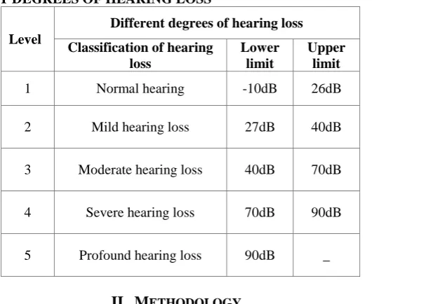
The huge scale of human population suffers from hearing loss. Hearing loss is a measure of shift in auditory system compared to that of normal ear for detection of a pure tone. But with the dexterity of modern technologies and the recent developments in signal processing area, the artificial hearing aid systems can be designed that to help the damaged auditory systems to a great extent and make much of the sound audible to the hearing impaired. In this project, the MATLAB programming language is used for development of simulation of the simple digital hearing. The construction of this digital hearing aid (DHA) system consists of noise reduction filter, frequency dependent amplification and amplitude compression. By testing with patient, successfully reduced whiteGaussian noise,increased the gain for frequencies which were difficult to hear and shaped the amplitude to prevent any of the frequencies from being too loud. At last, future trends and expected innovations in hearing aid system are described.TABLE I. DIFFERENT DEGREES OF HEARING LOSS
Level
Different degrees of hearing loss Classification of hearing
loss
Lower limit
Upper limit
1 Normal hearing -10dB 26dB
2 Mild hearing loss 27dB 40dB
3 Moderate hearing loss 40dB 70dB
4 Severe hearing loss 70dB 90dB
5 Profound hearing loss 90dB _
II.
M
ETHODOLOGYA block diagram for the MATLAB implementation of Digital Hearing Aid System is shown in Fig.1. The input speech signal takes the form of human voice. For producing an adjusted output speech signal which can be audible to the hearing impaired person the input speech signal will pass through several functions i.e., noise addition, noise reduction filter, frequency shaper and amplitude compression.
Input Speech Signal ↓
Noise Addition ↓
Noise Reduction Filter ↓ Frequency Shaper ↓ Amplitude Compression ↓ Output Speech
Fig:1 Block Diagram Representation of Hearing Aid System
A. Noise Addition
If the input speech signal for this system is a clean signal, some noise must be added to model a real situation. So the Additive White Gaussian Noise (AWGN) and random noise are added to the input speech signal by using MATLAB function. The noise (AWGN) has a continuous and uniform frequency spectrum over a specified frequency band and has equal power per Hertz of this band. This noise consists of all frequencies at equal intensity and has a normal (Gaussian) probability density function.
B. Noise Reduction Filter
A major anxiety for the people with hearing loss is the capability of hearing aid to differentiate intended speech signal in a noisy environment. Hence, to eliminate the noise, a reduction filter function is used in this design. To suppress the noise in the signal, the wavelet filter function is used.
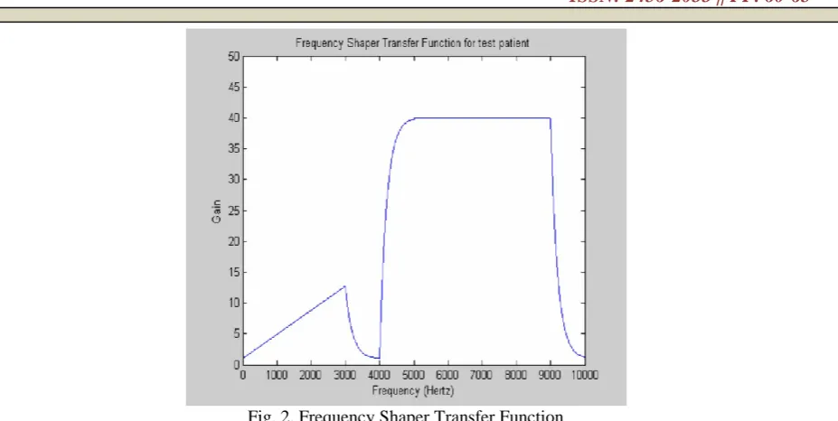
C. Frequency Shaper
Therefore, the frequency shaper is designed to correct for the loss of hearing at certain frequencies. It applies high gain for higher frequencies and vice versa.
D. Amplitude Compression
Amplitude compression function is the taskof controlling the overall gain of a speech amplificationsystem. Amplitude compression will ensure that the amplifiedsignal will not exceed saturation power.
III. IMPLEMENTATION
AND
SIMULATION
The code, written in MATLAB, loads the input speech signal, takes the sampling frequency and the number of bits of that signal. Then, Additive White Gaussian Noise (AWGN) and random noise are added to the signal before they are processed by various MATLAB functions to get an output which is audible to the hearing impaired person. For the analysis purpose, a sample of speech signal is selected. The sample is “I am DAMANA”. This signal is added by Additive White Gaussian Noise (AWGN) and random noise. To run the demo successfully, it is needed to input all the parameters which include maximum gain to be applied, saturation power and four frequency values where the gain changes. The patient suffers moderate hearing loss characterized by:
• Threshold of Hearing at 40 dB • Threshold of Pain at 110dB • Saturation level (Psat) of 90dB • Difficulty to hear high frequencies
Equations and Formulae Used
For FFT:
The resulting sequence is interpreted as follows:
X[k]= N−1x[n]
n=0 e−j2πkn /N, k = 0,1, … . N − 1; (1)
The zero frequency corresponds to n=0, positive frequencies0<f<Fs/2 correspond to values 1≤n≤N/2-1 while negativefrequencies correspond to N/2+1≤n≤N-1 [7]. Here, Fs denotes sampling frequency which is 22050 Hz here.The matrix obtained after performing this function containsframes of the original speech signal filtered by hamming filterand transformed with FFT. The elements of the matrix arecomplex numbers and symmetrical because FFT was used totransform. By calculating DFT we can obtain the magnitudespectrum.
For AWGN:
Y=s+10^(-Eb_N0_dB/20)*n;(2)
where „s‟ is the transmitted sequence, Eb_N0_dB is the SNRand „n‟ is the Additive White Gaussian Noise.
IV.
RESULTS
AND
DISCUSSION
Fig. 2. Frequency Shaper Transfer Function
Fig. 3 is the original speech signal which is plot on time versus amplitude axis.
Fig. 3. Input speech signal
Next, Additive White Gaussian Noise is added to theoriginal wave signal. The purpose of this addition is just tosimulate noises in the real life situation. Fig. 4 shows thesignal after noise addition.
Fig. 4. Corrupted speech signal
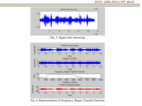
Fig. 5. Signal after denoising
Fig. 6. Representation of Frequency Shaper Transfer Function
Fig. 7. Spectrogram of Original and Adjusted Signals
V.
CONCLUSION
general, digital hearing aid converts the incoming signals to digital signals. This digitalization makes it possible to precisely analyze & filter the signals. The signals can be processed in one or more frequency channels. At the end, the digital signal is again converted to its analog form. The benefits of using digital aids can improve quality of life by improving sound quality.
References
[1] Frost and Sulliva, World Audiology Products Market,1997.
[2] Othman O. Khalifa, M.H. Makhtar and M.S. Baharom, “Hearing Aids System”, International Journal
of Computing & Information Sciences, Vol.2, No.1, April 2004.
[3] Shraddha D. Sharma and Devendra S. Chaudhari, “Speech Processing for Sensorineural Hearing
Impairment”, International Journal of Advanced Research in Computer Science and Software Engineering(IJARCSSE),Vol.3, Issue 3, March 2013.
[4] Navdeep Kaur and Dr. Hardeep Singh Ryait., “Study of Digital Hearing Aid Using Frequency Shaping
Function”, International Journal of Engineering Research and Technology (IJERT), Vol.2, Issue 5, May 2013.
[5] Robert W. Bauml and Wolfgang Sorgel, “Uniform Polyphase Filter Banks for Use in Hearing Aids”,
16th European Signal Processing Conference (EUSIPCO 2008), Lausanne, Switzerland, August 25-29,
2008.
[6] Sami Mohammed Halawani, Abdul Rahman Al-Talhi, Abdul Waheed Khan, “Speech Enhancement
Techniques for Hearing Impaired People: Digital Signal Processing based Approach”, Life Science Journal, Vol.10, No. 4, 2013.
[7] John G. Proakis and G.D. Manolakis., “Digital Signal Processing”, 5thedition, Prentice Hall, New Jersey, 2010 .
[8] Kamkar-Parsi,A.HBouchard, “Improved Noise Power SpectrumDensity Estimation for Binaural