Determining of Critical Solid Ratio of AISI 1020 Steel by Casting
Simulation
Murat Çolak
1, Fehim Findik
2,3,c1: Bayburt University, Engineering Faculty, Mechanical Engineering Dept. Bayburt, Turkey 2: Sakarya University, Technology Faculty, Metallurgy and Materials Eng. Dept, Sakarya, Turkey
3: Sakarya University, BIMAS-RC Research Center, Sakarya, Turkey
1. Introduction
Casting method and production of the part are a multiple process. The first process is designing the mould to form the parts geometry and the alloy to supply the required engineering properties. The second step is to design the runner and feeding system filling the mould cavity in regular form for liquid casting alloy and to supply void-free casting during the solidification. The design of part integrated with runner and feeding system is briefly defined as moulding design. The privileged conditions required for the moulding design are quality in casting and efficiency [1-4]. These criteria force to casting engineers in production cost and quality to produce casting in the highest quality but using the lowest metal (via minimum weight in runner and feeding system). Especially, a lot of cost increment and scrap risk form due to casting defects in moulding design via classical engineering methods in casting [1, 5]. On the other hand, the opinion is pervaded that possible quality problems are predicted and the risk is decreased during the design step in the casting designed by computer aided engineering techniques [6]. Whatever method is used, there are at least 4 main criteria required for paying attention in designing the stage of casting part for moulding [1, 6]. The aim of the present work is to determine the values of critical solid ratio (CFS) by means of casting simulation software in the casting of sand mould by the alloying of steel casting for AISI 1020. The solidified casting is cut and the produced porosities are inspected and the experimental results are compared with the results achieved from the SolidCast simulation software.
1.1 Hot point criterion
Hot point, that is isolated area, is defined as liquid zone surrounded (no connection with neighbour liquid zone) by solid metal during the solidification. It is required to determine the existing quantity of isolated hot point in casting cross section while doing the runner design. In runner design, hot point criterion is the most important principle to determine both the runner number and places in runner design. If a casting contains a different cross section thickness, more than one isolated hot points can form in casting and if possible cooling each hot points with a cooler, if not feeding with a runner system is essential. By implementing of this criterion correctly, there is no remaining of isolated hot point in casting part and forming of hot points on risers can safely be provided [1, 6-8].
Abstract:
One of the most important factors within the parameters is to define the resistance formed by solid dendrites growing against flow of liquid feeding in liquid region. Feeding is stopped when solid-liquid space blocked into solid-liquid flow. This point is defined as critical solid ratio (CFS). In the present study, it is aimed to determine the values of critical solid ratio (CFS) by means of casting simulation software in the casting of sand mould by the alloying of steel casting for AISI 1020. The solidified casting is cut and the formed porosities are examined and the experimental results are compared with the results obtained from the SolidCast simulation program. The results show that the feeding activity increases and as a result porosity formation decreases with the increment of critical solid ratio in sand casting prepared in the alloying of steel casting for AISI 1020. For this part, the CFS ratio is calculated as 60% in steel casting for AISI 1020. Furthermore, in this study an exact consistency has been obtained in the results of SolidCast simulation with the real casting marks attained from the sand casting by entering the data correctly.1.2 Solidification time (module) criterion
In designing for mould casting, the advancing of the solidification towards the risers and ending them in risers is defined as directional solidification and to supply this criterion, it is required for later solidification of riser from the hot points of casting. In sand casting, solidification time for a cross section can be calculated by Chvorinov approach as volume divided by area of a cross section. According to this approach;
t= k(V/A)2 [8]
In equation [8], t is solidification time as minutes, V is the volume of casting part, A is the surface area of casting part contacts to die, k is an equation constant change depending on the casting alloy and dies material.
(V/A) factor is defined as a module (M) and a riser module is required to be bigger than the casting module in proper design. According to this rule, the riser must be solidified later than the nearer hot point. This criterion is generally defined as the following equation [1, 2, 6-8].
(V/A)riser > (V/A)casting [8]
1.3 Riser volume necessity
All casting alloys are contracted as approximately 2 to 7 % as volumetrically during the cooling and solidification stages with some exceptions. This contraction named as volumetric shrinkage, can cause to be formed as a certain cavity in the last solidified regions (hot points) of casting parts. There is a particular feeding capacity of risers and this capacity can be limited as a determined volume. This limit defined as the following equation, none of riser should not be less than this volume due to the determination of the required minimum metal for riser in the production for no cavity casting.
Vb = α Vd /ε- α [1,6-8]
Here, Vb is the required volume of riser for a given casting (or for a certain feeding region in case of
using more than one riser). In case of using one riser, Vd is the volume of the part will be joined to riser. is the
volumetric shrinkage ratio for casting alloy as %. is the feeding metal can spend as % for total volume of the riser and this can be defined as “riser efficiency”. This ratio can be found as proportion of shrinkage formed in the upper surface to the total volume of riser in the centre after total solidification of riser [1, 6-8].
1.4 Feeding path criterion
There must be a feeding path, always be opened, having a particular heat gradient between the hot point and riser. This path should not be closed in preventing the feeding during the solidification. By this means, liquid metal running can be supplied from riser to the hot point. For an ideal casting, moulding design can only be obtained via supplying the whole above mentioned criterion [1, 6-8].
2. Computer aided casting design
Design of riser and runner system is quite difficult having complex geometry and different thickness in cross-section and sometimes this design cannot be possible via engineering calculations. However, via rapid development in computer technology, casting processes are modelled and the prediction of micro and macro structures is supplied via casting simulation programs [9, 10].
Modelling of casting processes is a mathematical method required for the rapid and correct prediction for computer while mould is filled and also what incidents happen in the mould after filling. Casting simulation programs is a technology established at the beginning of 1990 by foundries to predict the casting defects and to solve these problems in design stage prior to real casting. Casting simulations are modelling devices solving numerically the thermo-physical incidents in foundry for casting geometry as three dimensional, and also solving the required heat and mass transfer equations via finite difference or finite element method. The major targets are shown as follows for the casting modelling;
a. The quality of casting part must be increased during the mass production from the first casting,
b. To minimize the inlet duration for production of new casting part,
d. To remove rapidly the problems depending on the design during the production without trying the experimental methods [11].
To obtain the successful results in casting simulation programs depends on the inputting the real data into the computer for simulation program in real casting conditions. Some of these parameters can be mentioned such as casting temperature of alloy, contraction ratio, filling time of liquid metal to mould, the value for critical solid ratio can continue for feeding in solid-liquid interface. From these parameters the value of critical solid ratio, is an important parameter on solidification of casting part, feeding and simulation results in spite of no more studies worked on. Critical solid ratio is a point growing in a solid-liquid interface causing to stop of feeding to be blocking the liquid flow via reaching of dendrites to a certain volume, [1, 6, 12].
In this study, it is aimed to determine the values of critical solid ratio (CFS) by means of casting simulation software for sand moulding casting with AISI 1020 steel casting alloy. In order to determine the critical solid ratio, modelling study is done in different CFS values according to the real casting conditions. The solidified castings are cut and the formed porosity distributions are investigated and the obtained results are compared with the SolidState casting simulation outcomes and the critical solid ratio values are determined.
3. Experimental studies
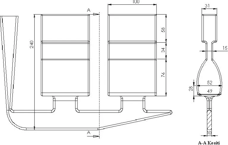
In the selection of modelling geometry employed in casting experiments, a model was used as thicker in the tips and thinner in the middle as shown in Figure 1. Thus, it was aimed that clear arising in the effect of critical solid ratio was aimed. On the upper side of the casting part, the presence of the liquid metal will feed the lower part, in case of materialising solidification in the level of critical solid ratio for the thinner part in the centre, feeding route will be closed and the liquid metal will no longer transfer to the lower part. Consequently, a defect formation was aimed in the lower part of the casting.
Figure 1. The geometry of casting model and its dimensions
The runner system of the part was designed in supplying the filling of liquid metal into the mold in a convenient speed without turbulance, agitation or any problem for filling. The modelling study was done in a FlowCast software for filling, the suitability of the runner system was controlled.
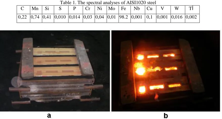
via CO2 gas. Then, three molds were placed side by side in the drag placing buffer between each other and they
were prepared for the casting as seen in Figure 2a. The casting was done from the AISI1020 steel into the prepared mold melted in induction furnace shown in Table 1. The view of mold after casting is given in Figure 2b.
Table 1. The spectral analyses of AISI1020 steel
C Mn Si S P Cr Ni Mo Fe Nb Cu V W Tİ
0,22 0,74 0,41 0,010 0,014 0,03 0,04 0,01 98.2 0,001 0,1 0,001 0,016 0,002
Figure 2. a) The view of mould ready to casting, b) Mould after the casting
The parts taken out of the mould after completing the casting process, the runners are cut and the casting samples are departed from the main metal. After that, the casting specimens are cut from the central part, the defects will possibly occur, and it is milled, and then the samples are ground and polished to see the porosities. Thus the porosity distribution on the samples is inspected and the running effective of each casting is defined in this way.
Figure 3. The used for the modelling of casting alloys a) thermal properties, b) curves.
4. Results and discussion
In this section, first the actual casting results and photographs of region occurring porosity will be given and then the casting simulation results will also be provided, these results will be compared with the actual casting results and the value for the critical solid ratio of the alloy will be determined.
4.1 Experimental results and assessment
The view of the moulding parts in casting process is seen in Figure 4. In case of examining the casting parts, it is seen that the liquid metal completely fills the mould cavity and there is no problem such as non-flowing in running system. In addition, no shrinkage cavity is observed in the outer surface of casting. Casting sprue side of the sample was named as the No. 1 and the other No. 2, and after that the samples referred to in this way. For examination, samples were cut so as to exceed the central section plane of the cutting process, and then they were milled before grinding later polished in order to appear in porosity.
The cross section of both samples is shown in Figure 5. Overall, the hottest point in the central regions of the shrinkage (porosity) was seen in the cast samples solidified the latest. It is understood that the formed porosities in these sections are the typical shrinkage porosities as sharp-edged and irregular shaped and they are formed due to inadequate feeding. In case of comparing the magnitude of porosities belongs to sample 1 and 2 in Figure 5, it is seen that more porosities are observed in the central part of sample 1 comparing to sample 2. This situation is formed due to the solidification of the part in the lower cooling rate of casting 1 sample remains between runner and sample 2. The wider solid-liquid region (mushyi) due to lower cooling rate reduces the effect of feeding a bit more comparing to sample 2 in this casting.
Figure 5. The views of cross section a) the sample in the runner side (1), b) sample in the outer side (2).
4.2 Simulation results and evaluation
The modelling studies of the casting part are done via SolidCast casting simulation program. In the scope of modelling studies, casting is done for primarily orientation of natural solidification of the part, location of the hot points and determining their magnitudes. It is seen in Figure 6a that a hot spot of 1.18cm size is formed in the part. Looking at Figure 6b in cross-section in solidification analysis, it is seen that these hot spots are the latest solidified places. Solidification is completed within 4.28 min in the thinner sections on the just above the hot spots, whereas the solidification continues 2 more minutes and then completed within 6.02 minutes in hot spots.
Then, all the parameters used in modelling are kept constant to determine the critical solid ratio in the program, and only the value of Critical Fraction of Solid (CFS) is changed. In this way, the actual casting results were based on the modeling and various modeling were done in different CFS values.
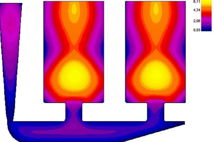
Figure 7. The view of casting porosity simulated according to the CFS 60 value, a) the equal (twin) surface view in 99.8% density, b) the view of central cross section plane between 99.5%-100%.
As a result of the comparison for the modelling and actual casting results, it is observed that the simulation outcomes are consistent with the actual casting results according to the CFS-60 value. In Figure 7, the porosity results are observed in a susceptibility of 99.8% according to the modelling employed for CFS 60%. In addition, comparing the porosity case obtained from the modelling in number 1 with number 2, more porosity is observed in number 1 case than number 2 consisting with the observation in the actual casting process. This situation confirms ones more that there is a consistency between modelling results and actual casting ones. The view of cross section in solidification and cooling analysis are given in Figure 8. Inspecting the cross section in solidification analysis, the reason of the shrinkage in the latest solidified region is blocking of the feeding route and reaching to the critical solid ratio due to earlier solidification depending on module of the thinner cross section in the centre.
5. Conclusions
1. AISI 1020 alloy, will not be fully fed, is casted in sand casting moulds designed for the investigation of the effects on the feeding degree of this hot spot of the critical solid ratio via forming a hot spot inside the mould. The values of critical solid ratio are determined according to the porosity amount in the applied castings. 2. The critical solid ratio was determined as 60% of CFS values as a result of the comparison for the values in actual casting and modelling ones.
3. Entering the porosity values measured from the actual castings and obtained from the simulation program, a perfect consistency was observed between the values for the modelled casting process. This proves that the values of materials properties entered into the program and boundary conditions were correctly selected. 4. Determining the most important factor of CFS value for each alloy in the modelling for casting, boundary conditions can be entered to simulation program and this supplies us a complete and accurate results.
6. References
[1]. Kayıkcı, R., Büyük kütleli bir çelik parçanın dökümünde klasik ve bilgisayar destekli mühendislik yöntemlerinin karşılaştırılması, Journal of The Faculty of Engineering and Architecture of Gazi University, Cilt 23, No 2, 2008.
[2]. Campbell, J., Castings, Butterworth-Heinemenn Ltd., Oxford, England, 1991.
[3]. Wlodower, R., Directional Solidification of Steel Casting, PergamonPress, Oxford, 1966. (Çeviren:
Yaman, M.,Çelik Dökümlerde Besleyici ve Soğutucu Hesapları, TMMOB Metalurji Müh.Odası,
1985.
[4]. Gwyn, M.A., “Cost-Effective Casting Design”, Engineered Casting Solutions, Moderncasting, 1999.
[5]. Kayıkcı, R., “Use of Computer Modelling in Predicting Microporosity in Commercial Aluminum
Alloy”, The 66 World Foundry Congress, İstanbul, 235-246, 2004.
[6]. Kayıkcı, R. ve Akar, N., “Farklı Kesit Kalınlıklarına Sahip Büyük Hacimli Bir Çelik Dökümün Simülasyon Teknikleri ile Tasarlanması”, Politeknik Dergisi, 10-4, 214-227, 2007.
[7]. Franssman, H., Hızlı ve Dogru Yolluk ve Besleyici Dizaynı için Döküm Simülasyon Programlarının Pratik Kullanımı, Metal Dünyası, 164, 30-31, 2007
[8]. Chvorinov, N., Theory of Solidification of Castings, Giesserei, 27, 177- 225, 1940.
[9]. http://www.finitesolutions.com/ (Eylül 2010)
[10]. Guleyupoglu, S., Casting Process Design Guidelines, AFS Transactions, 83, 869-876, 1997.
[11]. Kayıkcı, R., Nergis, M., Besleyicisiz Döküm Yöntemi İle Dökülen Bir Küresel Grafitli Dökme Demir
Dökümün İncelenmesi, 3. Uluslararası Döküm ve Çevre Sempozyumu (IFES2009), 28-29 Ocak 2010,
İstanbul, Türkiye
[12]. Kayıkcı, R., Çolak, M., „„Kuma Dökülen Etial160 Alüminyum Alaşımında Tane İnceltmenin
Beslenebilirlik Üzerine Etkisinin İncelenmesi‟‟, 5. Uluslararası İleri Teknolojiler Sempozyumu